NISSAN SENTRA 2001 B15 / 5.G Service Manual
Manufacturer: NISSAN, Model Year: 2001, Model line: SENTRA, Model: NISSAN SENTRA 2001 B15 / 5.GPages: 240, PDF Size: 1.92 MB
Page 41 of 240

TOP TETHER STRAP CHILD RE-
STRAINT
If your child restraint has a top tether strap,
it must be secured to the provided anchor
point. First, secure the child restraint with
the rear seat belt.Remove the anchor cover from the anchor
point which is located directly behind the
child seat.
Secure the top tether strap to the anchor
bracket. Tighten the strap according to
manufacturer instructions to remove any
slack.
WARNING
Child restraint anchor points are de-
signed to withstand only those loads
imposed by correctly fitted child re-
straints. Under no circumstances are
they to be used for adult seat belts or
harnesses.
Anchor point locations
Anchor points are located on the rear parcel
shelf finisher.
If you have any questions when install-
ing a top strap child restraint on the rear
seat, consult your NISSAN dealer for
details.
WRS0027WRS0028
1-34Seats, restraints and supplemental air bag systems
ZX
Page 42 of 240

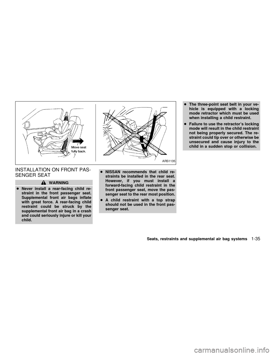
INSTALLATION ON FRONT PAS-
SENGER SEAT
WARNING
c
Never install a rear-facing child re-
straint in the front passenger seat.
Supplemental front air bags inflate
with great force. A rear-facing child
restraint could be struck by the
supplemental front air bag in a crash
and could seriously injure or kill your
child.cNISSAN recommends that child re-
straints be installed in the rear seat.
However, if you must install a
forward-facing child restraint in the
front passenger seat, move the pas-
senger seat to the rear most position.
cA child restraint with a top strap
should not be used in the front pas-
senger seat.cThe three-point seat belt in your ve-
hicle is equipped with a locking
mode retractor which must be used
when installing a child restraint.
cFailure to use the retractor's locking
mode will result in the child restraint
not being properly secured. The re-
straint could tip over or otherwise be
unsecured and cause injury to the
child in a sudden stop or collision.
ARS1135
Seats, restraints and supplemental air bag systems1-35
ZX
Page 43 of 240

If you must install a child restraint in the front
seat, follow these steps:
1. Position the child restraint on the front
passenger seat.It should be placed in
a front facing direction only.Move the
seat to the rearmost position. Always
follow the restraint manufacturer's in-
structions.Child restraints for infants
must be used in the rear facing direc-
tion and therefore must not be used in
the front seat.2. Route the seat belt tongue through the
child restraint and insert it into the buckle
until you hear and feel the latch engage.
Be sure to follow the child restraint manu-
facturer's instructions for belt routing.3. Pull on the shoulder belt until all of the
belt is fully extended. At this time, the
seat belt retractor is in the automatic
locking mode (child restraint mode). It
reverts back to emergency locking mode
when the seat belt is fully retracted.
WRS0019WRS0044WRS0045
1-36Seats, restraints and supplemental air bag systems
ZX
Page 44 of 240

4.Allow the seat belt to retract slightly. Pull
up on the seat belt to remove any slack in
the belt.5. Before placing the child in the child re-
straint, use force to tilt the child restraint
from side to side, and tug it forward to
make sure it is securely held in place.
6.
Check that the retractor is in the automatic
locking mode by trying to pull more seat
belt out of the retractor. If you cannot pull
any more belt webbing out of the retractor,
the seat belt is in the automatic locking
mode.
7. Check to make sure the child restraint is
properly secured prior to each use. If the
lap belt is not locked, repeat steps three
through six.After the child restraint is removed and the
seat belt is fully retracted, the automatic
locking mode (child restraint mode) is can-
celed.
WRS0046WRS0047
Seats, restraints and supplemental air bag systems1-37
ZX
Page 45 of 240

MEMO
1-38Seats, restraints and supplemental air bag systems
ZX
Page 46 of 240

2 Instruments and controls
Meters and gauges ................................................2-2
Speedometer and odometer .............................2-3
Tachometer (if so equipped) .............................2-4
Engine coolant temperature gauge ...................2-5
Fuel gauge ........................................................2-5
Warning/indicator lights and chimes ......................2-7
Checking bulbs ..................................................2-7
Warning lights ....................................................2-7
Indicator lights ...................................................2-9
Chimes.............................................................2-11
Security systems ..................................................2-11
Nissan vehicle immobilizer system
(NVIS) (if so equipped)....................................2-11
Vehicle security system (if so equipped) ........2-12
Windshield wiper and washer switch ...................2-15
Switch operation ..............................................2-15
Rear window defogger switch ..............................2-16
Headlight and turn signal switch ..........................2-16
Headlight control switch ..................................2-16
Turn signal switch............................................2-17Fog light switch (if so equipped) ..........................2-18
Hazard warning flasher switch .............................2-18
Horn ......................................................................2-19
Power socket ........................................................2-19
Cigarette lighter (accessory) and ashtray ............2-20
Storage .................................................................2-21
Glasses case (if so equipped).........................2-21
Cup holders .....................................................2-21
Glove box ........................................................2-22
Coin box ..........................................................2-22
Console box (if so equipped) ..........................2-23
Instrument panel storage ................................2-23
Windows ...............................................................2-24
Power windows (if so equipped) .....................2-24
Manual windows ..............................................2-25
Sunroof (if so equipped).......................................2-26
Interior light...........................................................2-27
Map lights (if so equipped)...................................2-27
Trunk light (if so equipped) ..................................2-28
ZX
Page 47 of 240

WIC0054
METERS AND GAUGES
2-2Instruments and controls
ZX
Page 48 of 240

SPEEDOMETER AND ODOM-
ETERSpeedometer
The speedometer indicates vehicle speed in
miles per hour (MPH) and kilometers per
hour (km/h).
Odometer
The odometer records the total distance the
vehicle has been driven.
WIC0030WIC0031LIC0050
Instruments and controls2-3
ZX
Page 49 of 240

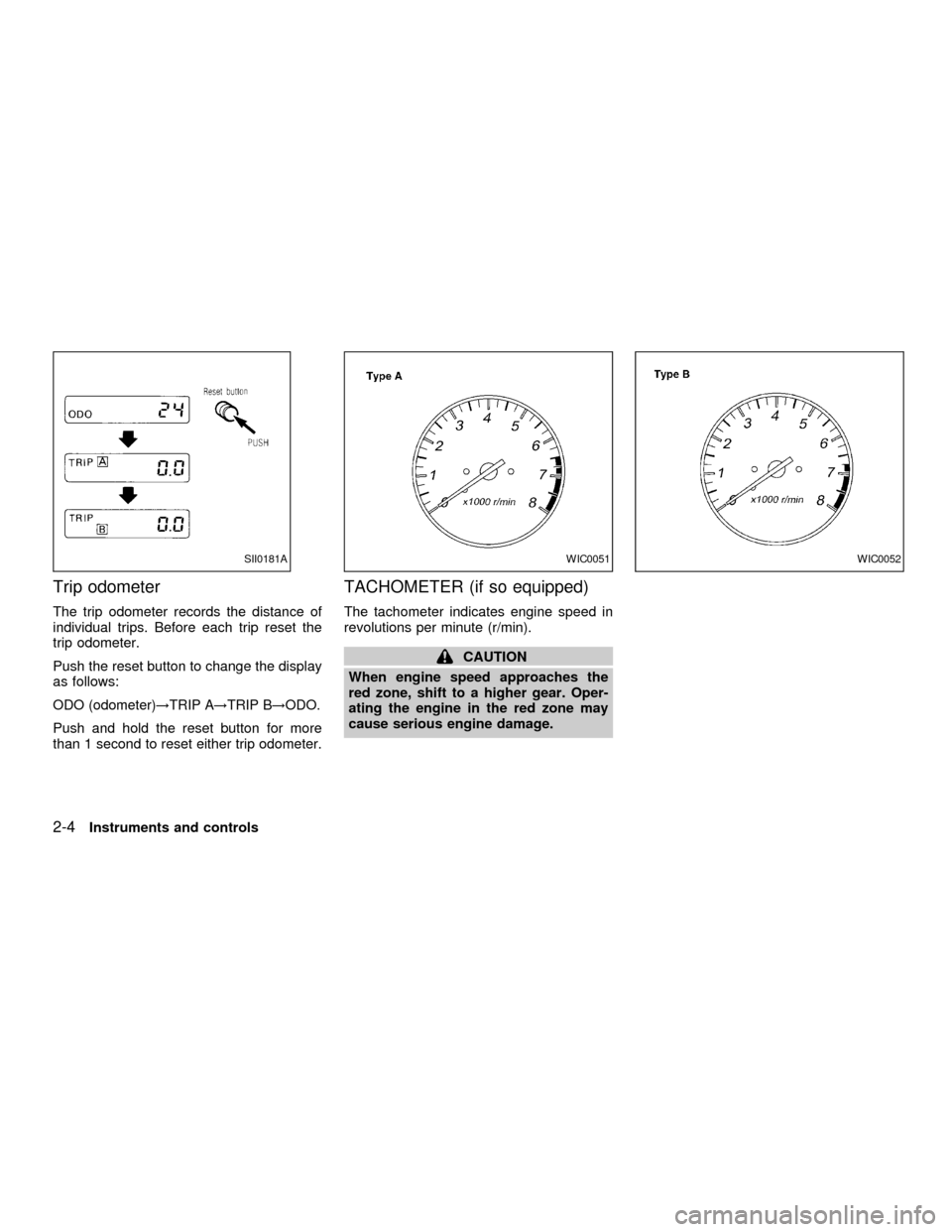
Trip odometer
The trip odometer records the distance of
individual trips. Before each trip reset the
trip odometer.
Push the reset button to change the display
as follows:
ODO (odometer)!TRIP A!TRIP B!ODO.
Push and hold the reset button for more
than 1 second to reset either trip odometer.
TACHOMETER (if so equipped)
The tachometer indicates engine speed in
revolutions per minute (r/min).
CAUTION
When engine speed approaches the
red zone, shift to a higher gear. Oper-
ating the engine in the red zone may
cause serious engine damage.
SII0181AWIC0051WIC0052
2-4Instruments and controls
ZX
Page 50 of 240

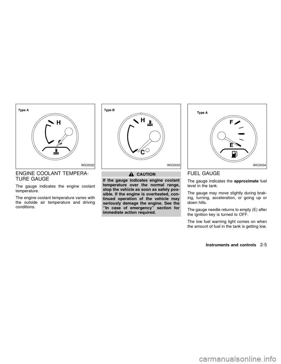
ENGINE COOLANT TEMPERA-
TURE GAUGE
The gauge indicates the engine coolant
temperature.
The engine coolant temperature varies with
the outside air temperature and driving
conditions.
CAUTION
If the gauge indicates engine coolant
temperature over the normal range,
stop the vehicle as soon as safely pos-
sible. If the engine is overheated, con-
tinued operation of the vehicle may
seriously damage the engine. See the
``In case of emergency'' section for
immediate action required.FUEL GAUGE
The gauge indicates theapproximatefuel
level in the tank.
The gauge may move slightly during brak-
ing, turning, acceleration, or going up or
down hills.
The gauge needle returns to empty (E) after
the ignition key is turned to OFF.
The low fuel warning light comes on when
the amount of fuel in the tank is getting low.
WIC0032WIC0033WIC0034
Instruments and controls2-5
ZX