traction control NISSAN SENTRA 2020 Owner´s Manual
[x] Cancel search | Manufacturer: NISSAN, Model Year: 2020, Model line: SENTRA, Model: NISSAN SENTRA 2020Pages: 528, PDF Size: 3.56 MB
Page 106 of 528
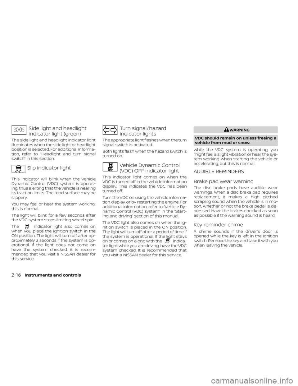
Side light and headlight
indicator light (green)
The side light and headlight indicator light
illuminates when the side light or headlight
position is selected. For additional informa-
tion, refer to “Headlight and turn signal
switch” in this section.
Slip indicator light
This indicator will blink when the Vehicle
Dynamic Control (VDC) system is operat-
ing, thus alerting that the vehicle is nearing
its traction limits. The road surface may be
slippery.
You may feel or hear the system working;
this is normal.
The light will blink for a few seconds af ter
the VDC system stops limiting wheel spin.
The
indicator light also comes on
when you place the ignition switch in the
ON position. The light will turn off af ter ap-
proximately 2 seconds if the system is op-
erational. If the light does not come on
have the system checked. it is recom-
mended that you visit a NISSAN dealer for
this service.
Turn signal/hazard
indicator lights
The appropriate light flashes when the turn
signal switch is activated.
Both lights flash when the hazard switch is
turned on.
Vehicle Dynamic Control
(VDC) OFF indicator light
This indicator light comes on when the
VDC is turned off in the vehicle information
display. This indicates the VDC has been
turned off.
Turn the VDC on using the vehicle informa-
tion display, or by restarting the engine. For
additional information, refer to “Vehicle Dy-
namic Control (VDC) system” in the “Start-
ing and driving” section of this manual.
The VDC light also comes on when the ig-
nition switch is placed in the ON position.
The light will turn off af ter a period of time if
the system is operational. If the light stays
on or comes on along with the
indica-
tor light while you are driving, have the VDC
system checked. It is recommended that
you visit a NISSAN dealer for this service.
WARNING
VDC should remain on unless freeing a
vehicle from mud or snow.
While the VDC system is operating, you
might feel a slight vibration or hear the sys-
tem working when starting the vehicle or
accelerating, but this is normal.
AUDIBLE REMINDERS
Brake pad wear warning
The disc brake pads have audible wear
warnings. When a disc brake pad requires
replacement, it makes a high pitched
scraping sound when the vehicle is in mo-
tion, whether or not the brake pedal is de-
pressed. Have the brakes checked as soon
as possible if the warning sound is heard.
Key reminder chime
A chime sounds if the driver's door is
opened while the key is lef t in the ignition
switch. Remove the key and take it with you
when leaving the vehicle.
2-16Instruments and controls
Page 248 of 528
Static: Caused by thunderstorms, electrical
power lines, electric signs and even traffic
lights.
AUDIO OPERATION PRECAUTIONS
MP3 or WMA terms
• MP3 — MP3 is short for Moving PicturesExperts Group Audio Layer 3. MP3 is the
most well-known compressed digital au-
dio file format. This format allows for near
“CD quality” sound, but at a fraction of the
size of normal audio files. MP3 conversion
of an audio track from CD-ROM can re-
duce the file size by approximately a 10:1
ratio with virtually no perceptible loss in
quality. MP3 compression removes the
redundant and irrelevant parts of a
sound signal that the human ear doesn’t
hear.
• WMA — Windows Media Audio (WMA)* is a compressed audio format created by Mi-
crosof t as an alternative to MP3. The WMA
codec offers greater file compression
than the MP3 codec, enabling storage of
more digital audio tracks in the same
amount of space when compared to
MP3s at the same level of quality. • Bit rate — Bit rate denotes the number of
bits per second used by a digital music
file. The size and quality of a compressed
digital audio file is determined by the bit
rate used when encoding the file.
• Sampling frequency — Sampling fre- quency is the rate at which the samples
of a signal are converted from analog to
digital (A/D conversion) per second.
• Multisession — Multisession is one of the methods for writing data to media. Writ-
ing data once to the media is called a
single session, and writing more than
once is called a multisession.
• ID3/WMA Tag — The ID3/WMA tag is the part of the encoded MP3 or WMA file that
contains information about the digital
music file such as song title, artist, encod-
ing bit rate, track time duration, etc. ID3
tag information is displayed on the Artist/
song title line on the display.
* Windows® and Windows Media® are reg-
istered trademarks and trademarks in the
United States of America and other coun-
tries of Microsof t Corporation of the USA.
USB (Universal Serial Bus)
Connection Port
WARNING
• Do not connect, disconnect or oper-
ate the USB device while driving. Do-
ing so can be a distraction. If dis-
tracted you could lose control of your
vehicle and cause an accident or se-
rious injury.
CAUTION
• Do not force the USB device into the
USB port. Inserting the USB device
tilted or up-side-down into the port
may damage the port. Make sure
that the USB device is connected cor-
rectly into the USB port.
• Do not grab the USB port cover (if so
equipped) when pulling the USB de-
vice out of the port. This could dam-
age the port and the cover.
• Do not leave the USB cable in a place
where it can be pulled unintention-
ally. Pulling the cable may damage
the port.
4-46Monitor, climate, audio, phone and voice recognition systems
Page 256 of 528
USB (Universal Serial Bus)
CONNECTION PORT
Connecting a device to the USB
Connection Port
WARNING
Do not connect, disconnect, or operate
the USB device while driving. Doing so
can be a distraction. If distracted you
could lose control of your vehicle and
cause an accident or serious injury.
CAUTION
• To avoid damage and loss of function
when using a USB device, note the
following precautions.
• Do not force the USB device into the
USB port. Inserting the USB device
tilted or up-side-down into the port
may damage the port. Make sure
that the USB device is connected cor-
rectly into the USB port.
• Do not grab the USB port cover (if so
equipped) when pulling the USB de-
vice out of the port. This could dam-
age the port and the cover.
• Do not leave the USB cable in a place
where it can be pulled unintention-
ally. Pulling the cable may damage
the port.
For additional information, refer to your de-
vice manufacturer's owner information re-
garding the proper use and care of the
device.
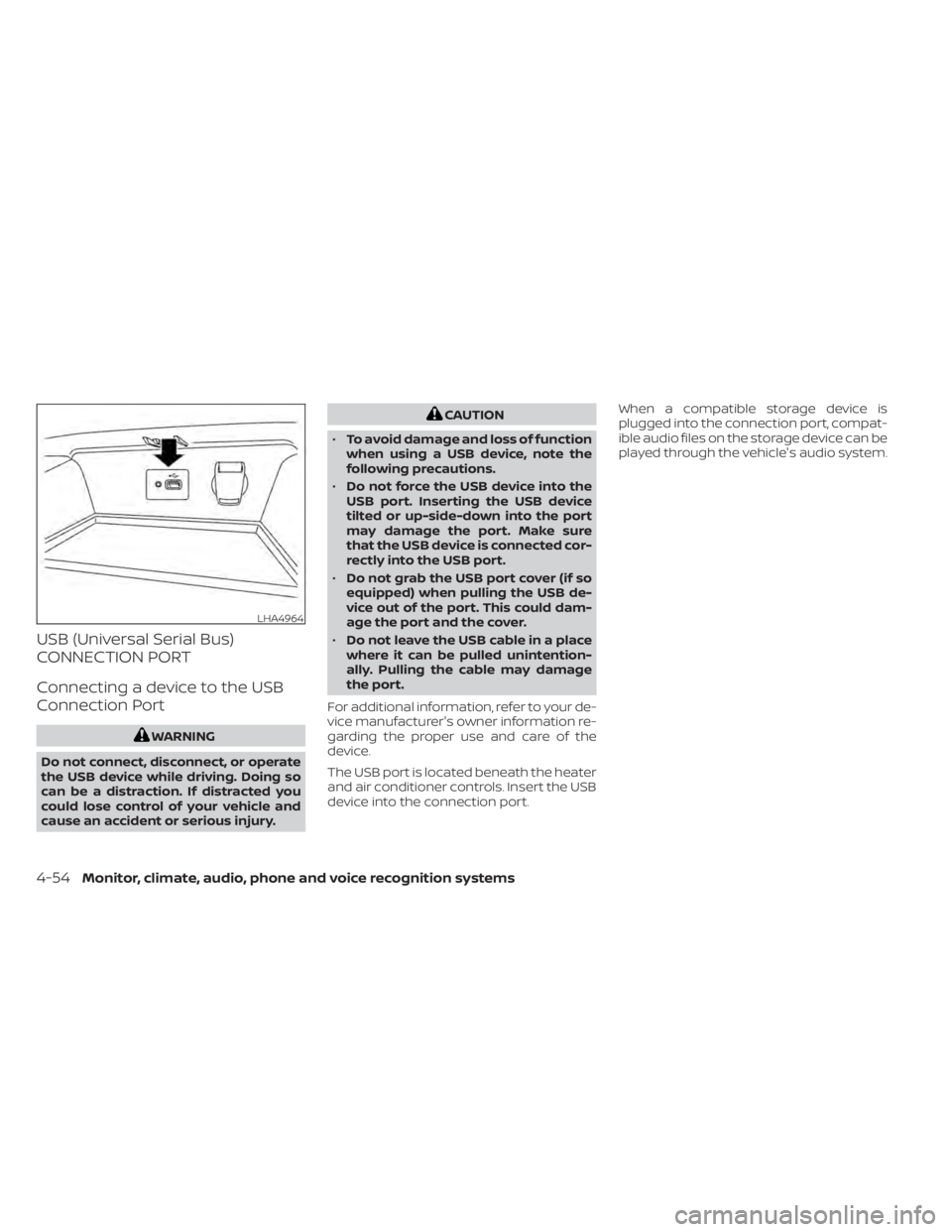
The USB port is located beneath the heater
and air conditioner controls. Insert the USB
device into the connection port. When a compatible storage device is
plugged into the connection port, compat-
ible audio files on the storage device can be
played through the vehicle's audio system.
LHA4964
4-54Monitor, climate, audio, phone and voice recognition systems
Page 259 of 528
iPod®* PLAYER OPERATION
Connecting iPod®
WARNING
Do not connect, disconnect, or operate
the USB device while driving. Doing so
can be a distraction. If distracted you
could lose control of your vehicle and
cause an accident or serious injury.
CAUTION
• Do not force the USB device into the
USB port. Inserting the USB device
tilted or up-side-down into the port
may damage the port. Make sure
that the USB device is connected cor-
rectly into the USB port.
• Do not grab the USB port cover (if so
equipped) when pulling the USB de-
vice out of the port. This could dam-
age the port and the cover.
• Do not leave the USB cable in a place
where it can be pulled unintention-
ally. Pulling the cable may damage
the port.
For additional information, refer to your de-
vice manufacturer’s owner information re-
garding the proper use and care of the
device.
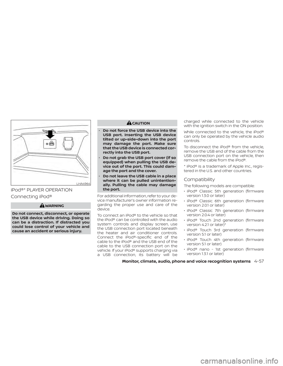
To connect an iPod® to the vehicle so that
the iPod® can be controlled with the audio
system controls and display screen, use
the USB connection port located beneath
the heater and air conditioner controls.
Connect the iPod®-specific end of the
cable to the iPod® and the USB end of the
cable to the USB connection port on the
vehicle. If your iPod® supports charging via
a USB connection, its battery will be charged while connected to the vehicle
with the ignition switch in the ON position.
While connected to the vehicle, the iPod®
can only be operated by the vehicle audio
controls.
To disconnect the iPod® from the vehicle,
remove the USB end of the cable from the
USB connection port on the vehicle, then
remove the cable from the iPod®.
* iPod® is a trademark of Apple Inc., regis-
tered in the U.S. and other countries.
Compatibility
The following models are compatible:
• iPod® Classic 5th generation (firmware
version 1.3.0 or later)
• iPod® Classic 6th generation (firmware version 2.0.1 or later)
• iPod® Classic 7th generation (firmware version 2.0.4 or later)
• iPod® Touch 2nd generation (firmware version 4.2.1 or later)*
• iPod® Touch 3rd generation (firmware version 5.1 or later)
• iPod® Touch 4th generation (firmware version 5.1 or later)
• iPod® nano - 1st generation (firmware version 1.3.1 or later)LHA4964
Monitor, climate, audio, phone and voice recognition systems4-57
Page 266 of 528
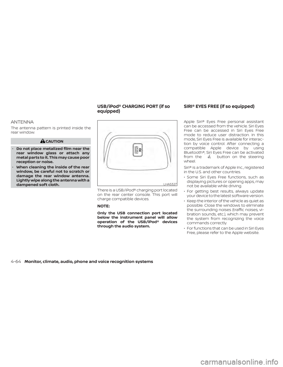
ANTENNA
The antenna pattern is printed inside the
rear window.
CAUTION
• Do not place metalized film near the
rear window glass or attach any
metal parts to it. This may cause poor
reception or noise.
• When cleaning the inside of the rear
window, be careful not to scratch or
damage the rear window antenna.
Lightly wipe along the antenna with a
dampened sof t cloth.
There is a USB/iPod® charging port located
on the rear center console. This port will
charge compatible devices.
NOTE:
Only the USB connection port located
below the instrument panel will allow
operation of the USB/iPod® devices
through the audio system. Apple Siri® Eyes Free personal assistant
can be accessed from the vehicle. Siri Eyes
Free can be accessed in Siri Eyes Free
mode to reduce user distraction. In this
mode, Siri Eyes Free is available for interac-
tion by voice control. Af ter connecting a
compatible Apple device by using
Bluetooth®, Siri Eyes Free can be activated
from the
button on the steering
wheel.
Siri® is a trademark of Apple Inc., registered
in the U.S. and other countries.
• Some Siri Eyes Free functions, such as displaying pictures or opening apps, may
not be available while driving.
• For getting best results, always update your device to the latest sof tware version.
• Keep the interior of the vehicle as quiet as possible. Close the windows to eliminate
the surrounding noises (traffic noises, vi-
bration sounds, etc.), which may prevent
the system from recognizing the voice
commands correctly.
• For functions that can be used in Siri Eyes Free, please refer to the Apple website.
LHA5327
USB/iPod® CHARGING PORT (if so
equipped) SIRI® EYES FREE (if so equipped)
4-64Monitor, climate, audio, phone and voice recognition systems
Page 391 of 528
For Canada
This device complies with Industry
Canada licence-exempt RSS standard(s).
Operation is subject to the following two
conditions:
1.This device may not cause
interference,
2. This device must accept any interfer-
ence, including interference that may
cause undesired operation of the
device.WARNING
Failure to follow the warnings and in-
structions for proper use of the I-DA
system could result in serious injury or
death.
• The I–DA system is only a warning to
inform the driver of a potential lack
of driver attention or drowsiness. It
will not steer the vehicle or prevent
loss of control.
• The I–DA system does not detect and
provide an alert of the driver’s lack of
attention or fatigue in every
situation.
• It is the driver’s responsibility to:
– stay alert,
– drive safely,
– keep the vehicle in the traveling lane,
– be in control of the vehicle at all times,
– avoid driving when tired,
– avoid distractions (texting, etc). The I–DA system helps alert the driver if the
system detects a lack of attention or driv-
ing fatigue.
The system monitors driving style and
steering behavior over a period of time,
and it detects changes from the normal
pattern. If the system detects that driver
attention is decreasing over a period of
time, the system uses audible and visual
warnings to suggest that the driver take a
break.
INTELLIGENT DRIVER ALERTNESS
(I-DA)
Starting and driving5-105
Page 402 of 528
BRAKE ASSIST
When the force applied to the brake pedal
exceeds a certain level, the Brake Assist is
activated generating greater braking force
than a conventional brake booster even
with light pedal force.
WARNING
The Brake Assist is only an aid to assist
braking operation and is not a collision
warning or avoidance device. It is the
driver’s responsibility to stay alert,
drive safely and be in control of the ve-
hicle at all times. The VDC system uses various sensors to
monitor driver inputs and vehicle motion.
Under certain driving conditions, the VDC
system helps to perform the following
functions:
• Controls brake pressure to reduce wheel
slip on one slipping drive wheel so power
is transferred to a non-slipping drive
wheel on the same axle.
• Controls brake pressure and engine out- put to reduce drive wheel slip based on
vehicle speed (traction control function).
• Controls brake pressure at individual wheels and engine output to help the
driver maintain control of the vehicle in
the following conditions:– Understeer (vehicle tends to not follow the steered path despite increased
steering input)
– Oversteer (vehicle tends to spin due to certain road or driving conditions)
The VDC system can help the driver to
maintain control of the vehicle, but it can-
not prevent loss of vehicle control in all driv-
ing situations. When the VDC system operates, the
indicator light in the instrument panel
flashes to note the following:
• The road may be slippery or the system
may determine some action is required
to help keep the vehicle on the steered
path.
• You may feel a pulsation in the brake pedal and hear a noise or vibration from
under the hood. This is normal and indi-
cates that the VDC system is working
properly.
• Adjust your speed and driving to the road conditions.
For additional information, refer to “Slip in-
dicator light” and ”Vehicle Dynamic Control
(VDC) OFF indicator light” in the ”Instru-
ments and controls” section of this manual.
If a malfunction occurs in the system, the
indicator light comes on in the instru-
ment panel. The VDC system automatically
turns off when the indicator light is off.
The vehicle information display is used to
turn off the VDC system. The
indicator
light and the AEB system warning light illu-
minates to indicate the VDC system is off.
VEHICLE DYNAMIC CONTROL (VDC)
SYSTEM
5-116Starting and driving
Page 474 of 528
O6Term of “tubeless” or “tube type”
Indicates whether the tire requires
an inner tube (“tube type”) or not
(“tubeless”).
O7The word “radial”
The word “radial” is shown if the tire
has radial structure.
O8Manufacturer or brand name
Manufacturer or brand name is
shown.
Other Tire-related Terminology
In addition to the many terms that
are defined throughout this section,
Intended Outboard Sidewall is (1) the
sidewall that contains a whitewall,
bears white lettering or bears
manufacturer, brand, and/or model
name molding that is higher or
deeper than the same molding on
the other sidewall of the tire, or (2)
the outward facing sidewall of an
asymmetrical tire that has a particu- lar side that must always face out-
ward when mounted on a vehicle.
TYPES OF TIRES
WARNING
• When changing or replacing tires, be
sure all four tires are of the same type
(i.e., Summer, All Season or Snow)
and construction. A NISSAN dealer
may be able to help you with infor-
mation about tire type, size, speed
rating and availability.
• Replacement tires may have a lower
speed rating than the factory
equipped tires, and may not match
the potential maximum vehicle
speed. Never exceed the maximum
speed rating of the tire.
• Replacing tires with those not origi-
nally specified by NISSAN could af-
fect the proper operation of the low
tire pressure warning system. •
Always use tires of the same type,
size, brand, construction and tread
pattern on all four wheels. Failure to
do so may result in a circumference
difference between tires on the front
and rear axles which can cause the
Vehicle Dynamic Control (VDC) sys-
tem to malfunction resulting in per-
sonal injury or death, excessive tire
wear and may damage the transmis-
sion and differential gears.
• For additional information regarding
tires, refer to “Important Tire Safety
Information” (US) or “Tire Safety In-
formation” (Canada) in the Warranty
Information Booklet.
All season tires
NISSAN specifies All Season tires on some
models to provide good performance all
year, including snowy and icy road condi-
tions. All Season tires are identified by ALL
SEASON and/or M&S on the tire sidewall.
Snow tires have better snow traction than
All Season tires and may be more appropri-
ate in some areas.
8-34Do-it-yourself
Page 513 of 528
Manual Transmission (if so
equipped)
• Always tow with the manual transmis-sion in N (Neutral).
• Af ter towing 500 miles (805 km), start and idle the engine with the transmission in N
(Neutral) for two minutes. Failure to idle
the engine af ter every 500 miles (805 km)
of towing may cause damage to internal
transmission parts.
Continuously Variable
Transmission (if so equipped)
To tow a vehicle equipped with a continu-
ously variable transmission, an appropriate
vehicle dolly MUSTbe placed under the
towed vehicle's drive wheels. Alwaysfollow
the dolly manufacturer's recommenda-
tions when using their product. DOT (Department of Transportation) Qual-
ity Grades: All passenger car tires must
conform to federal safety requirements in
addition to these grades.
Quality grades can be found where appli-
cable on the tire sidewall between tread
shoulder and maximum section width. For
example:
Treadwear 200 Traction AA Temperature
A
Treadwear
The treadwear grade is a comparative rat-
ing based on the wear rate of the tire when
tested under controlled conditions on a
specified government test course. For ex-
ample, a tire graded 150 would wear one
and one-half (1 1/2) times as well on the
government course as a tire graded 100.
The relative performance of tires depends
upon the actual conditions of their use,
however, and may depart significantly from
the norm due to variations in driving habits,
service practices and differences in road
characteristics and climate.
Traction AA, A, B and C
The traction grades, from highest to low-
est, are AA, A, B, and C. Those grades repre-
sent the tire's ability to stop on wet pave-ment as measured under controlled
conditions on specified government test
surfaces of asphalt and concrete. A tire
marked C may have poor traction perfor-
mance.
WARNING
The traction grade assigned to this tire
is based on straight-ahead braking
traction tests, and does not include ac-
celeration, cornering, hydroplaning, or
peak traction characteristics.
Temperature A, B and C
The temperature grades are A (the high-
est), B, and C, representing the tire’s resis-
tance to the generation of heat, and its
ability to dissipate heat when tested under
controlled conditions on a specified indoor
laboratory test wheel. Sustained high tem-
perature can cause the material of the tire
to degenerate and reduce tire life, and ex-
cessive temperature can lead to sudden
tire failure. The grade C corresponds to a
level of performance which all passenger
car tires must meet under the Federal Mo-
tor Safety Standard No. 109. Grades B and A
represent higher levels of performance on
the laboratory test wheel than the mini-
mum required by law.
UNIFORM TIRE QUALITY GRADING
Technical and consumer information10-19