NISSAN SERENA 1993 Service Repair Manual
SERENA 1993
NISSAN
NISSAN
https://www.carmanualsonline.info/img/5/57387/w960_57387-0.png
NISSAN SERENA 1993 Service Repair Manual
Trending: tow, jump start, radiator, USB, light, low beam, fuse diagram
Page 691 of 1254
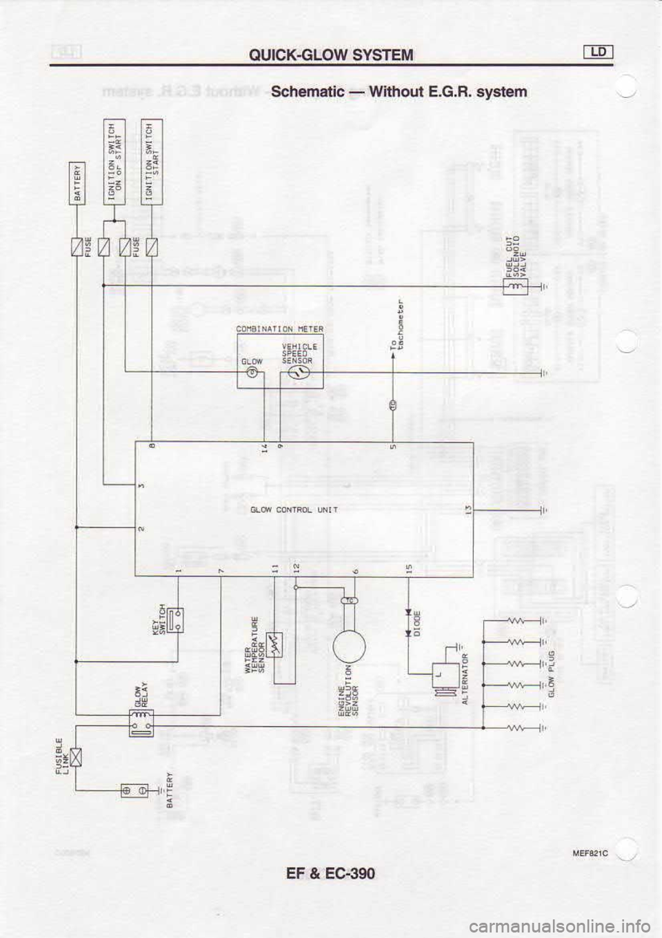
OUICKGLOW
SYSTEiI
;F 6e
a
:tltFrE
Schem€tlc
-
Wllfiout E.G.R. sysr€m
!
c ,i
'E
a
|dt
3=
EF & EC:('SO
Page 692 of 1254
OUICK€LOW
SYSTEM
Description
IL
] lJL
11- .-
i tj.
--[-
H" J--
jI
JL|L
-I-i;L
ftdr>T" ri!__
liii ru
^'lr
I
L,-.1
Wh€nlhsig.irion k6y i6 ns€nedtntothe
key cyti.d6r, th6.on-
trcl lnit luhs on
lhe elay and 'high
levol" 6ler c curcnt llo$
lhrcuqh lh€
Alow pluqs
and heats $€m up quickly.
When the
ign lion 6wilch is tlmed o., th€ onrrclunl luhs
on the indie-
lor. Atler T1 seconds have pssd
lrom k€y in, the codot unit
ions oll lh6 indi€tor. whil€
chnklng, the €lay rcma n5
on.
Th€ rc ay aulomalica
ly tums olt an€r T. s€6nd.
hav€ p4sed
EF & EC€91
Page 693 of 1254
OUICKGLOW
SYSTEM
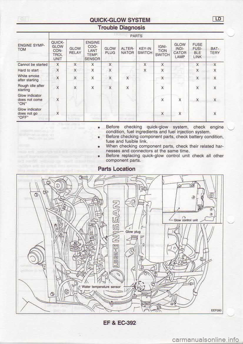
Trouble Diagnosis
. Belo€
.h€cking qlick-glow
system, check engn6
@ndilion, luel ing€dients and luel lnt€clion
sy6t€m.
. BoloG
checking component pans,
chek baliery co.dition,
tlse and lusible
link.
. Whe. checkinq @mponenl pans,
ch€ck rher crst€d haF
ne$6 and connedoA at lhe sam€ rm€.
. Setore rcplacing quick
g ow @nlrc unl ch6ck al
other
Pgrts Location
\-
EF & EC€92
Page 694 of 1254
OUICK€LOW
SYSTEM
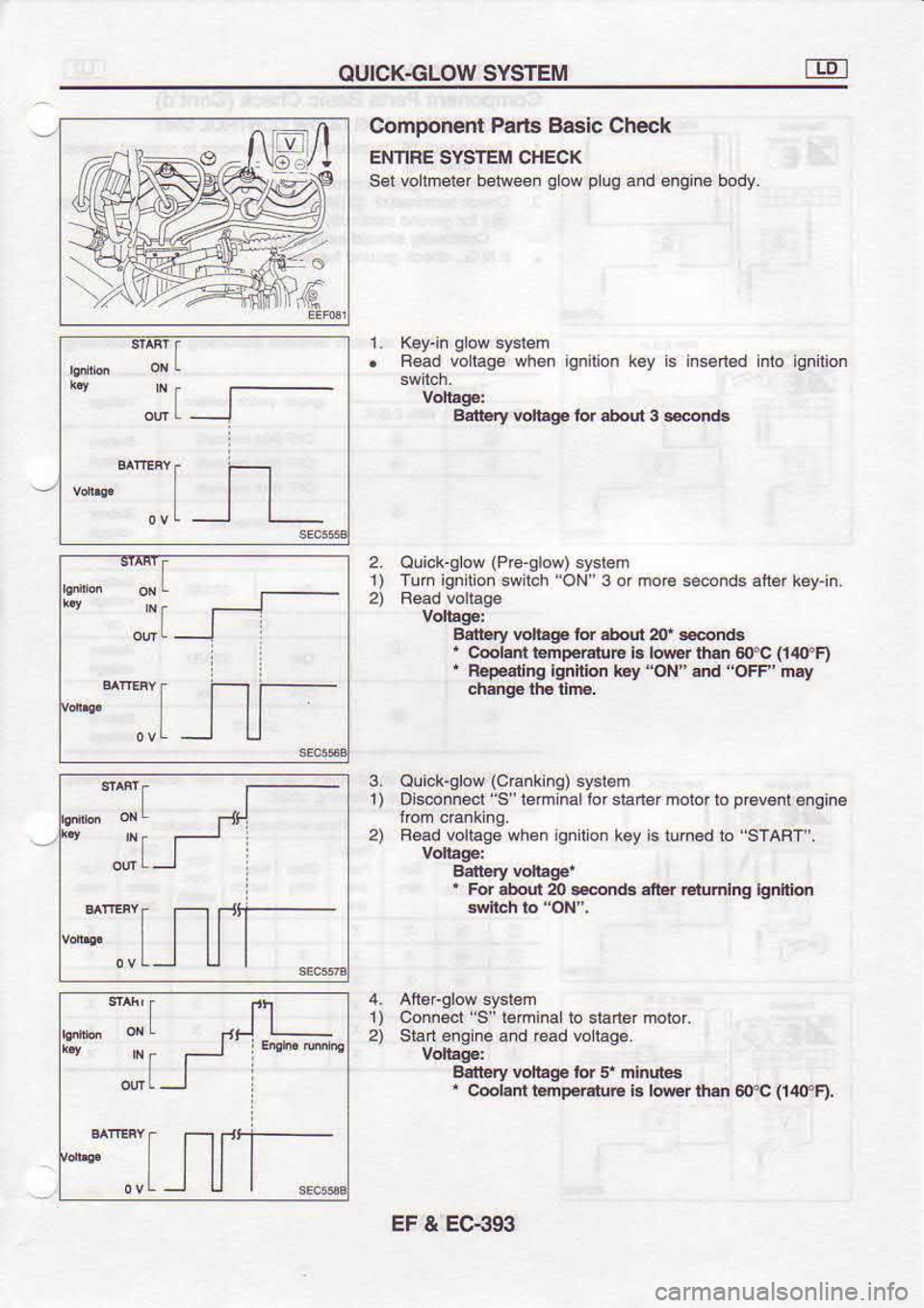
Comoonent Parts Baslc Ch€ck
ENNFE SYSTEM CHECK
ser vortmeier bellleen grow
plug
and engine body.
. Read voLiag6 when ieniton ksy is i.sd€d into ignilion
Ern6ry v!{agp ior abolt 3 6n.rs
2. ouick-glow (Pre-slow)
syslem
1) Iuh ignihon swtch 'ON
3 or mor6 sconds ai1* k€y-in.
Adbry v!t!g. for .hqit 2lf
snd8
' c@|am r.mp.r.ruF b low $.n 6{rc (i4cn
' R.p.6dnq lgdnon i6y oN"sd oFF'nly
chlngE th. tim,
n
^f
{rjllT *"s-
Ouick-slow (c€nkind
.ysr€m
1) Oisconnecl
"9 lemlnal
lor sianef moior lo prev€nl
6nain6
2) F€d vollage when igniroi k6y is rum€d to "STABT .
Balt ry hltag.'
, For .bod m snd. aner Ermhg
lgddm
1) Connecl
"S" l€minalto
daner motor.
2) Start engine and €ad voltagB.
Barbry rcnag. id 5r mhur€s
, Cdrani t6np.€t!b b rtur
ihs 6fC (14OF).
*Tt
TIJI
T:I
EF & EC€gi'
Page 695 of 1254
OUICK€LOW
SYSTEM
Et6
ffi l__
I aol
u*
Idg:rud:le
Componenl
Pads Basic Check (Cont'd)
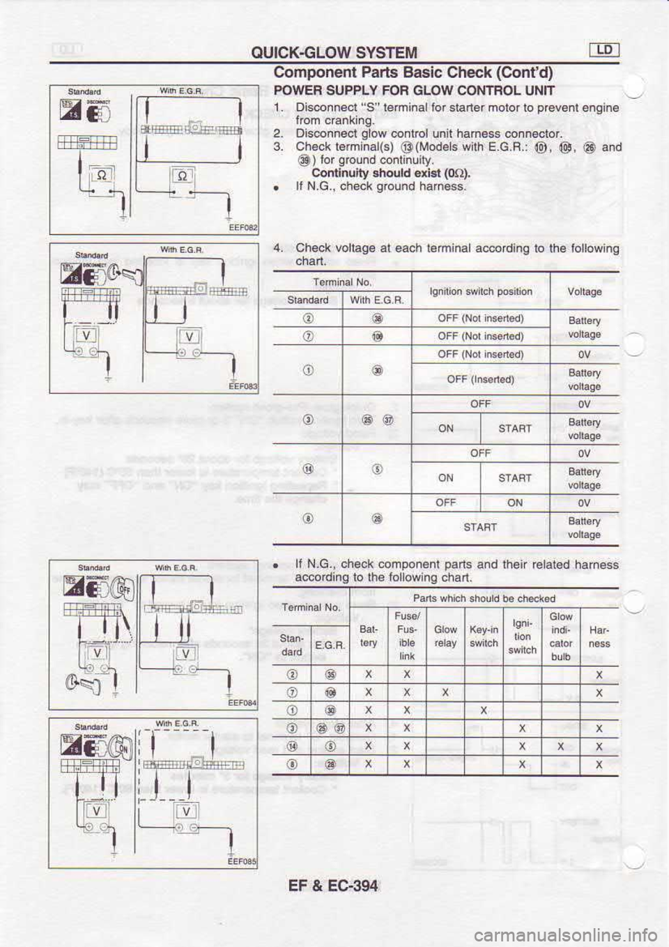
POWER SUPPLY FOF
GLOW CONTFOL UNIT
1. Ois@nnecl S"temiia tor $aner molor lo prcverl
engine
2. [email protected]| glow
conl@l un t hah€ss enneclof.
3. ch6ck l6m nal(s)
@(Mod6ls wilh
E.G.R.:
@, @, @ and
@) lor
grolnd
conlinuily.
condnuhy 3h@rd dj3t (m),
. It N.G., checkgound hane$.
li 4.
ch6ck vollage
al each leminal accodinq to the lonowing
o o
o (e
o o
o @@
@ o
o @
. ll
N.G-, check
@mponenl Dans and
then re|at€d h.m€ss
a@odinglo lhe lonowing chan.
@ @
o o
o @
@ 6@
@ o
o @
@at
EF & EC-394
Page 696 of 1254
OUICK€LOW
SYSTEM
Component Paris Basic
Check (Confd)
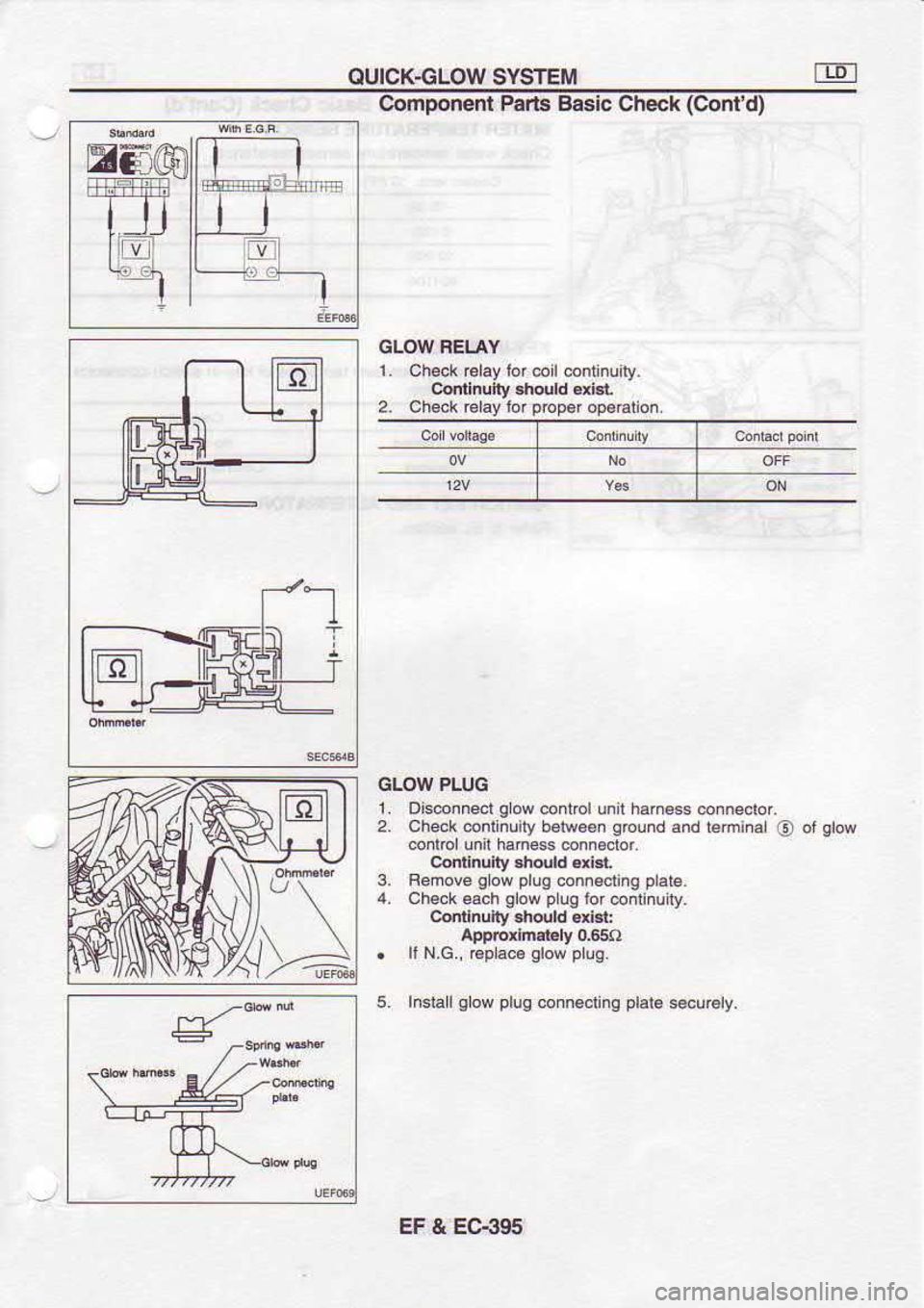
GLOW FEI.AY
1. Check @lay lor coil .onrinuily.
Cqnh!fty .,hould €ri8t
2. Check relay lor prcp$
op.alion.
GLOW PLUG
2.
3. Ois@nneol
glow
coni@l unt h.h€.s onnector
Check @nlinuily b6tw6..
Ablnd and
teminal
@
co rol unit ham6s conndctor.
confinuit shdld 6xi3r
Remov6 gow
plug
conn€clinq plale.
Chek 6ach glow
plug
tor @ inuity_
Contlnualy 3hould oxlsl:
appbrh.tdy 0.65f)
ll N.G., Gp ace glow
plug.
5. In$allglow plug
conn€cling plata.ecurely,
EF & EC-395
Page 697 of 1254
OUICK.GLOW
SYSTEM E
C,omponent Parta
Basic Check (Cont'd)
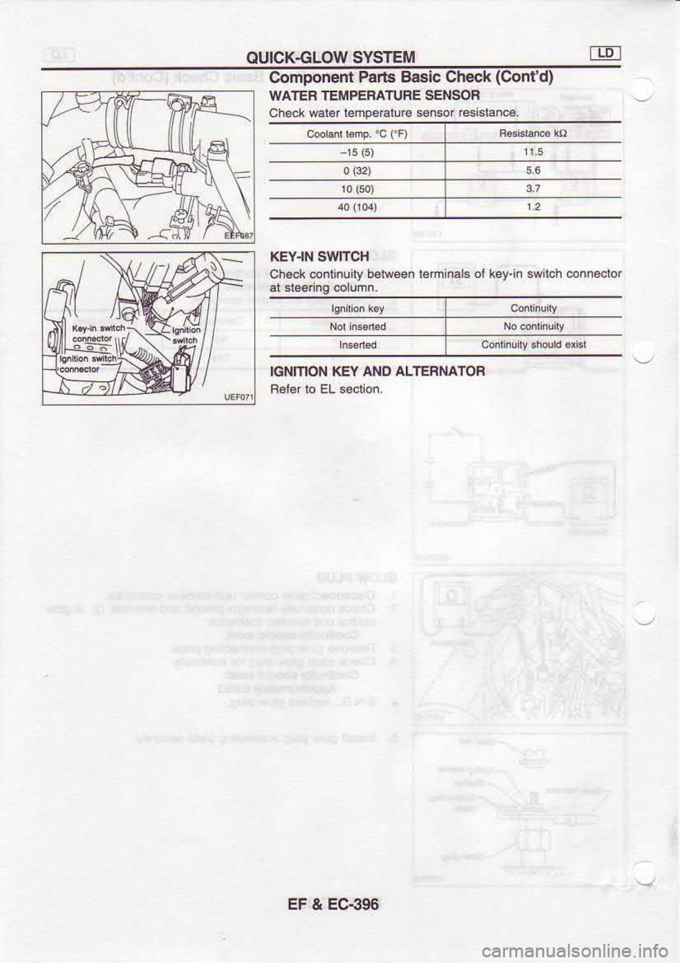
WATEB TEMPEBATURE SENSOF
Check warer
lBmp.€turc sensor rcsistance,
KEY.IN SIVITCH
ch€ck @ntinully belween leminals ot key.i. swilch 6n..ctor
IGNITION KEY ANO ALTEBNATOF
EC€96
Page 698 of 1254
E.G.B.
SYSTEM
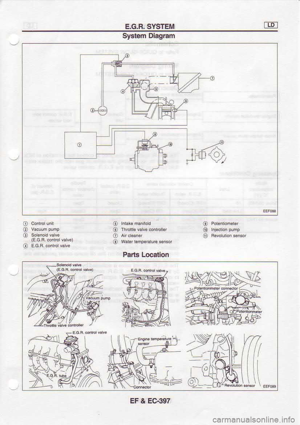
Syatem Dlagram
o
@
@
o
o
o
o
o
o
o
o Pans Locatlon
--/ EF & EC-397
Page 699 of 1254
E.G,R,
SYSTEM
Sch6malic Feler to outcK-GLow sYsTEir.
Wiring Diagram
Felef to olJtcK GLow sYsTEM.
De€crlplion
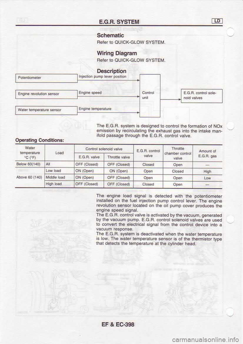
The F
G F
sysrem is d€srgnod ro
contrcr l.e .omation
o, NOr
emission by €circulalng
the exhaust gas
into th6 i.taka
man-
ilod psege
through lhe E.c.B. onrrot valve.
The enqne load
signal is
dot€ci€o wirh
lhe pol6ntion€r€r
insr.ned o. lhe '!el
ijecrion p-mp
cori@l laer. Tre e.g'ne
€eoluiion s€nsof lo€ted
on the oil pump
cov* pod!@s
the
Th€ E.G.R.
contol valve is aclivar€d by
lh€ vacuuh, g.n.€t€d
by rh€ vacuum pump.
E.G.R. @nrrclslenold
vatves aG us6d
lo conv€rl
lhe elecl @l signal fbm rha
contrcl devicg inlo a -
The E,G,B. syst6m is d€acrivated
when ihe wal6r lempeaturc
is low. The w.t€r lempehlue
sensor is oJ lh€ th6mi6tor
type
lhat d6l€cls lh€ r€mDeElure
ai th€ qlind€r
head.
EF & EC-398
Page 700 of 1254
E.G.R.
SYSTEM
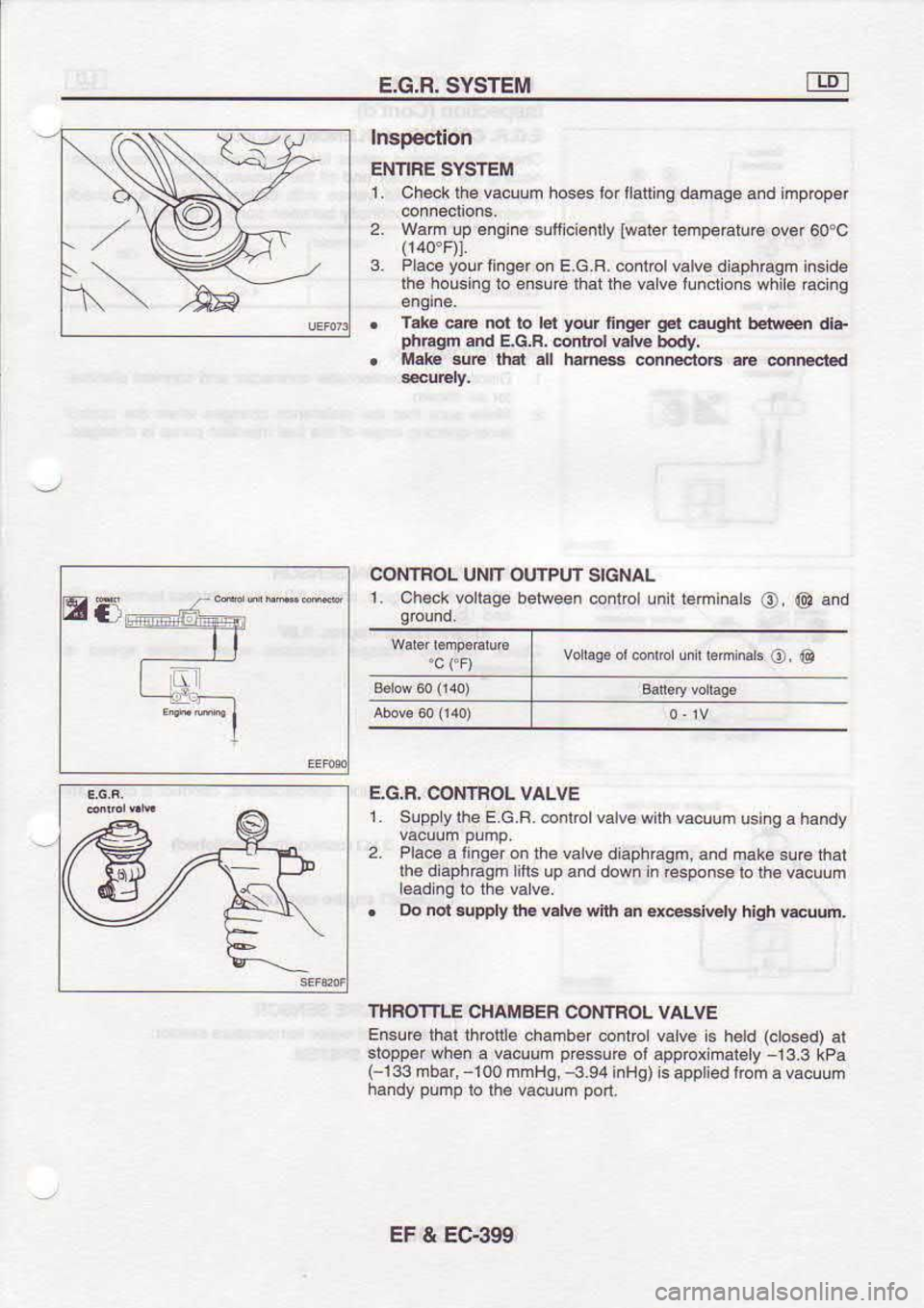
Inspeclion
ENNFE SYSTEM
1. C h€ck lhe vacuum hoses Io r llatting damaqe snd m prop6r
2. w.m up €ngine
s!fiici€nlly
lwatertenperatu.6 ovor
60oc
3. Placa yow
tinger on E.G.B. co.l@l valve diaphEAm i..ide
lh€ houshg
lo e.sJre lhsl lhe vav€ fLncro-s while
acng
Take @E not lo ld your
fingE q€r
eugh betweei
dla
PftElm and
E.G.R,onlrol vdE
body,
Mek &E ih.l all
hffi conn6io6 .6 drFcted
E5 @NIROL
UNIT OUTPUT SIGNAL
1. Chek vollage
between conlol unir reminals
O, @ and
vo6F ormdre lirh'hn*
o @
E.G.8. CONIAOL VALVE
1. Slpplylhe E.G.B. @nlrolvalv€ with vacuud
using a handy
2. Pla€
a linger
on the valv6 diaphraqm,
and mak€ surc lhat
lhe diaphEgm litls up and down in
€6ponse b lh€ vacuum
. Do
nol {pply lh. v.lv. with
an q6slvely
high wum.
ITIFOTTLE CHAMBEF
CONTBOL
EnsuE lhar rhbrile
chamber conrrcl
slopper wh€.
a vacuum p.€ssu6
ol
(-133mbar, 100 mmHs. -3.9r
inHg)
handy pump
to the vacuum pon. valv€
i. held (clced)
al
approximaiely 13.3 kPa
ls appliedlrcm
a vacuum
EF & EC.39S
Trending: set clock, wiring diagram, check oil, sunroof, change time, fuel filter, Engine mount
![NISSAN SERENA 1993 Service Repair Manual OUICK€LOW
SYSTEM
Description
IL
] lJL
11- .-
i tj.
--[-
H" J--
jI
JL|L
-I-i;L
ftdr>T" ri!__
liii ru
^lr
I
L,-.1
Wh€nlhsig.irion k6y i6 ns€nedtntothe
key cyti.d6r, th6.on-
trcl lnit lu NISSAN SERENA 1993 Service Repair Manual OUICK€LOW
SYSTEM
Description
IL
] lJL
11- .-
i tj.
--[-
H" J--
jI
JL|L
-I-i;L
ftdr>T" ri!__
liii ru
^lr
I
L,-.1
Wh€nlhsig.irion k6y i6 ns€nedtntothe
key cyti.d6r, th6.on-
trcl lnit lu](/img/5/57387/w960_57387-691.png)
