engine oil NISSAN SERENA 1993 Service Repair Manual
[x] Cancel search | Manufacturer: NISSAN, Model Year: 1993, Model line: SERENA, Model: NISSAN SERENA 1993Pages: 1254, PDF Size: 89.68 MB
Page 644 of 1254
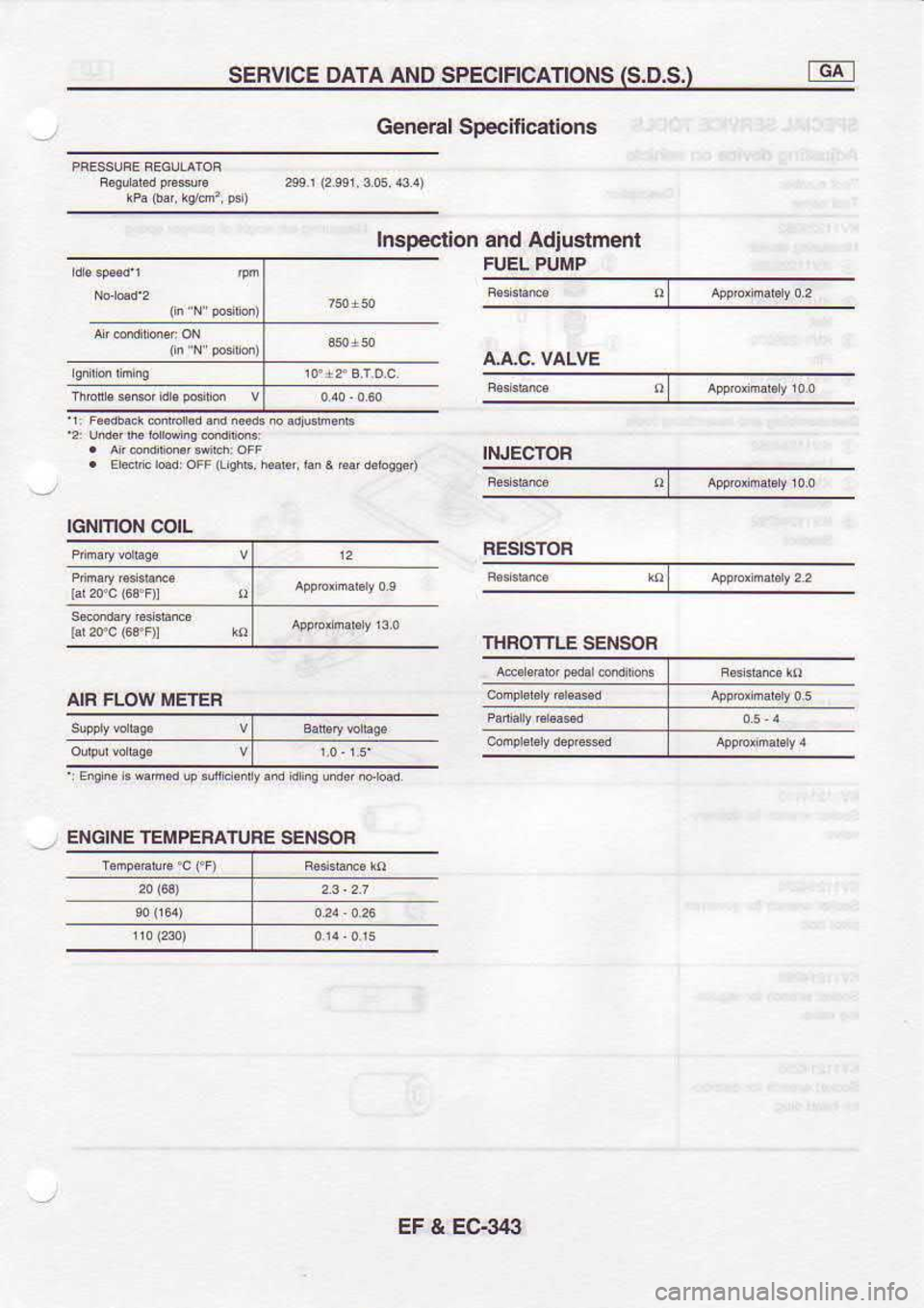
SERVTCE
DATA AND SPECTFTCATTONS (S.D.S.)
General SDecitications
Inspeclion and Adiustment
INJECTOF RESISTOF
THROTTLE SENSOF
AIF FLOW METER
ENGINE TEMPEHATUFE
IGNITION
COIL
SENSOB
EF & EG34:}
Page 885 of 1254
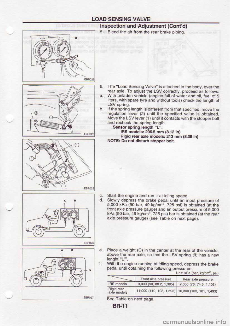
LOAD
SENSING VALVE
Inspeclion and Adius:menl(Cont'd)
5, Bleedlhe anlom lhe r6af brake pipinq.
The 'Load
Se.s ng Valv€ is attachad
to the body, ovor lh€
reai axle. To adjust lh€ Lsv
@irectly, p@ce€d
as iollows:
With unladen v€hicl€ (engine
lullol wal€r and oil,lle
of5
lilerc, wilh sparc lyr6
and wilhoul lools) ch€ck lhe lenath
ot
lf rh6 spnna bnalh
is d llercnt trom rhal sp& lied.
move lhe
€qu.lion lever (2)
unlillh6 specilied value
is oblan6d.
Move lhe LSVlever(l)un
n @ntacts w ih fie sbDD€r bol
and @check lh6 spnng
bnglh.
SeMr spd.g
|mgrh 'L':
lRs modob: a)6,5 mn la.12lnl
Flgld @r db modeGi 213
mfr (a3a
in)
NOTE: Do nol dialub Etopper
bolt
Stan lhe
enqine and run I al dinq
speed.
Slowly deprcss lh€ bEke peda
uitit an inpur pr6ssu@
ot
5,000 kPa (50
bar,49 kg/.m?,
725 psi)
is obrained (at
lhe
loni axle p€ssu€
Oalge)and an
oulputpressu€
o15.000
kPa (50
bar,49 kg/cm?,725 psl)baris
obiain€d (at
lhe €ar
axl6 p€ssu€
qauge)(seeTabe
on ne{ paae).
6. Pace
a weghr (c)
in rhe
center at lhe Gar oi
tha vehicte,
above the Gaf axl€, so
thal the Lsv sp nq
\6) has
a new
L Wth
lhe engine runninq al idlinq
speed, deprcss the
brake
pedal u|li obtainino
lhe followins prcssures:
gR-l1
Page 951 of 1254
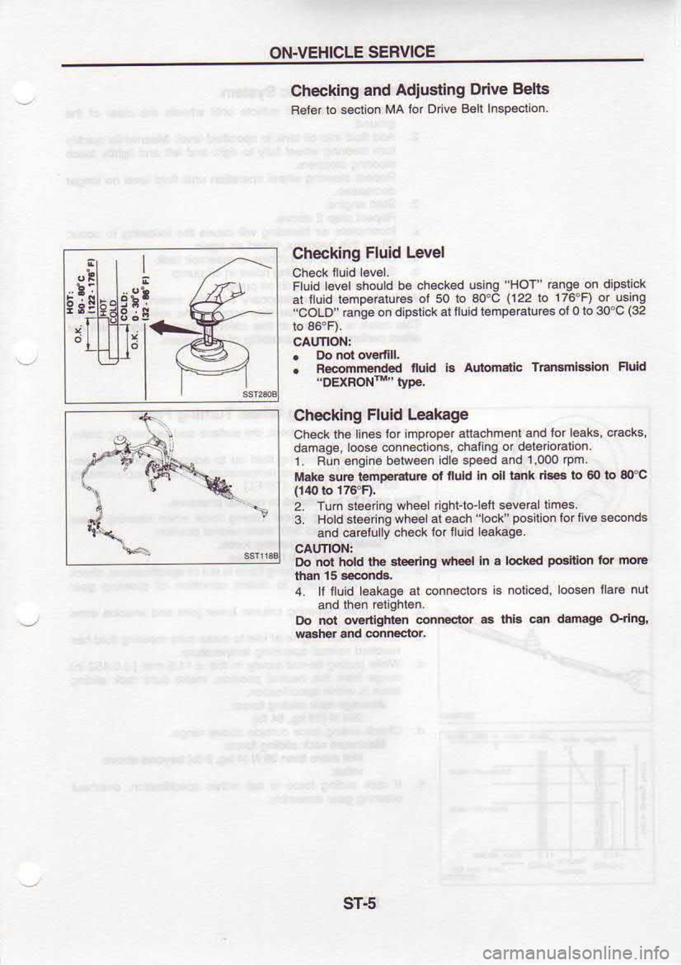
ON.VEHICLE
SEBVICE
f4 s- Checkidg
and
Adjusting Ddve B€lts
Beler lo secl
on MA ior
Drve Belt Inspecton
Checking Fluid
Level
Fluid Levershoud be
cheoked usinq HoT
Enge on
dipslrck
at iluid lenoeratur€s ol
50 b ao'C (122
lo 176'F) ot
usmg
'coLo" Gnoe on
d pstck
allluidlempeEtures ol0
to 30'c (32
. Rdnrended fuid
b adomsiic Transmlslon Fluid
Checking Fluid
Leakage
Check lhe
linos lof mproper allachmenl
and lor
l6aks, c6cks,
damage,loose conneclions chal
ng or deleio€lion.
i Bun engine b€ftveen
idLe speed and
1,000 .pm
M.k€ suE lentEr.tuE ot
fluld ln oil
l.nk des to 60lo 30Pc
2. Turn
s1€efne wheel rqhl-to'etl
seve6 limes.
3. Hold sl€ernq
wheelal each 'ock'poslio.lorr
ve s.conds
and carelully check
lor fu d eak.ge
Do not hold the 3teeting sh.€l
in a lek d pGiton
lor moE
4. ll tluid l€akace al
conneclo6 s
noliced, loosen rar€
nll
tro not ovedlgtn n
connectd as lhiB
c.. damage Orlng.
t
i
i
!
t
i
Y3 ri
l:
E
Page 1131 of 1254
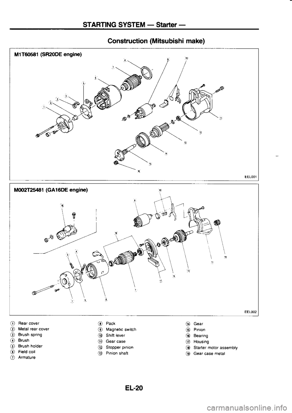
STARTING
SYSTEM -
Starter -
Construction (Mitsubishi
make)
M1T6681 (SR2oDE
engine)
O Rear
cover
O Metal
rear
cover
O Brush
spring
O Brush
@ Brush
holder
@ Field
coil
O Armature O
Pack
@ Magnetic
switch
@ Shitt
lever
@ Gear
case
@ Stopper
prnion
@ Pinion
shalt @
Gear
'rt Hrnron
@ Bearing
@ Housing
(} Starter motor
assembly
(t Gear case metal
EL-20
Page 1132 of 1254
STARTING
SYSTEM -
Stader-
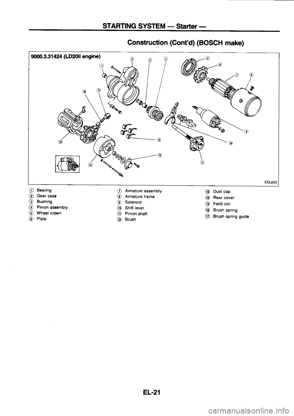
9q)0.3.31 424 (LlI2Oll
engine)
wk
w$ FF.-,
@ /K:b@;-" I@----.*
Construction
(Cont'd)
(BOSCH
make)
O Armature
assembly
@ Dust
cap
O Bearing
O Gear
cass
O Bushing
O Pinion
ass€mbty
@ wheel
crown
O Plate @
Armature
lrame
@ Solenoid
@ shitt
tever
O Pinion
shatt
@ Brush @
Rear
cover
@ Field
coil
@ Brush
spring
O Brush
spring guide
EL.21
Page 1134 of 1254
STARTING
SYSTEM _
Starter _
Dismantling (SR20DE,
GA1 6DE) (Cont'd)
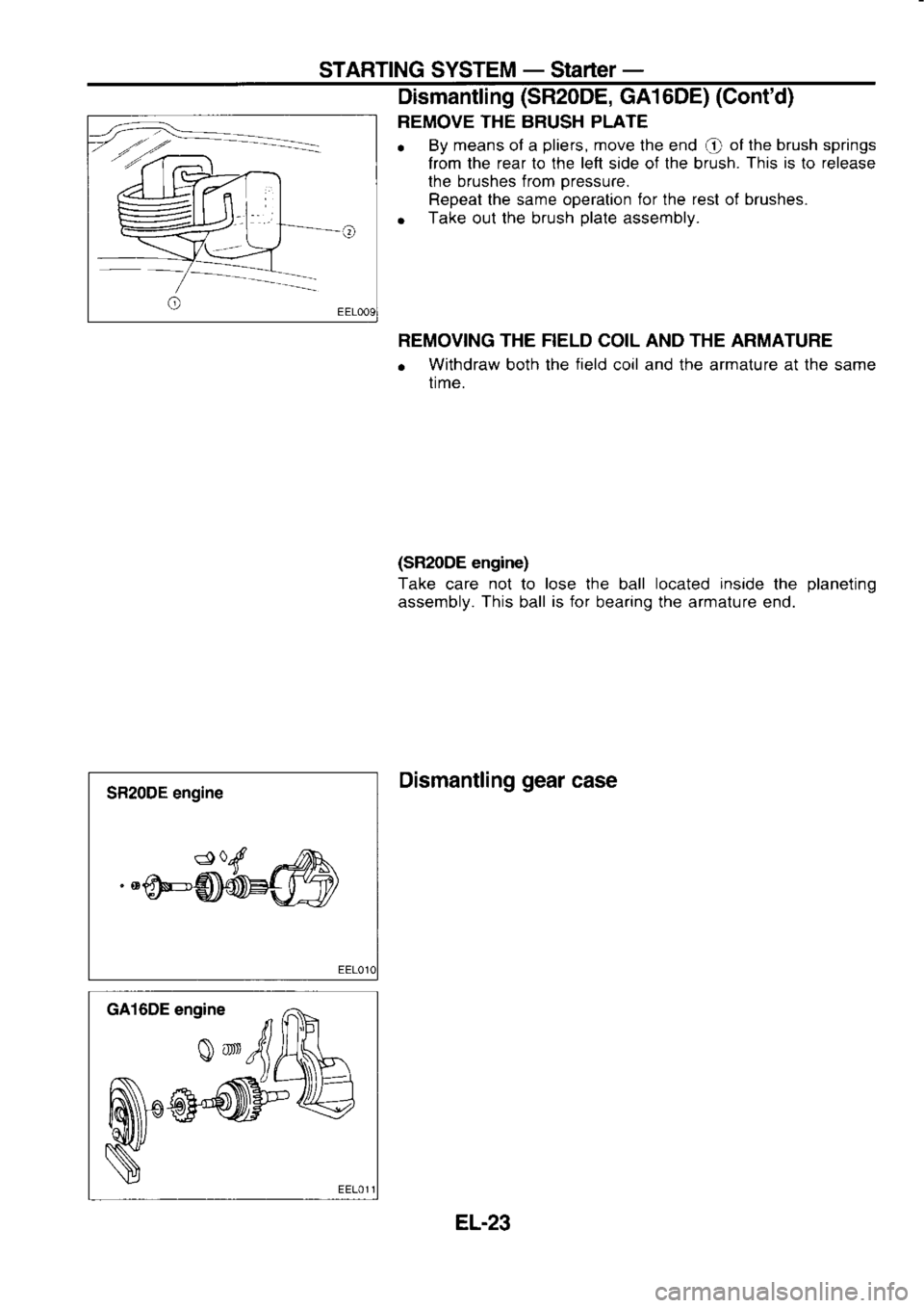
REMOVE THE BRUSH PLATE
o By
means of a pliers,
move the end
@ of
the brush springs
Irom the rear lo the left side of the brush. This
is
to release
the brushes from pressure.
Repeat the same operation for
the rest
of brushes.
o Take
out the brush plate
assembly.
REMOVING THE FIELD COIL AND THE ARMATURE
o Withdraw
both the field
coil and the armature at the same
time.
(SMODE engine)
Take care not
to lose
the ball located
inside
the planeting
assembly. This ball is
for
bearing the armature end.
Dismantling gear
case
SR20DE engine
EL-23
Page 1138 of 1254
STARTING
SYSTEM -
Starter -
Assembly
Apply h igh-temperature grease
to lubricate
the bearing, gears
and frictional
surface when
assembling the starter.
Care{ully observe
the following inslructions.
Assembly at next
order:
. Gear
case
Pinion assembly and shift lever,
musl be mounted together.
. Ring
and pinion
shaft.
. (sR20DE)
Put the ball in
its hole.
o Field
coil and armature frame, must
be mounted
together.
Don't lock the holes of screws.
o Armature
f rame.
o Brush
holder.
Check the correct alignment of holes
of screws.
o Rear
cover.
. Magnetic
switch.
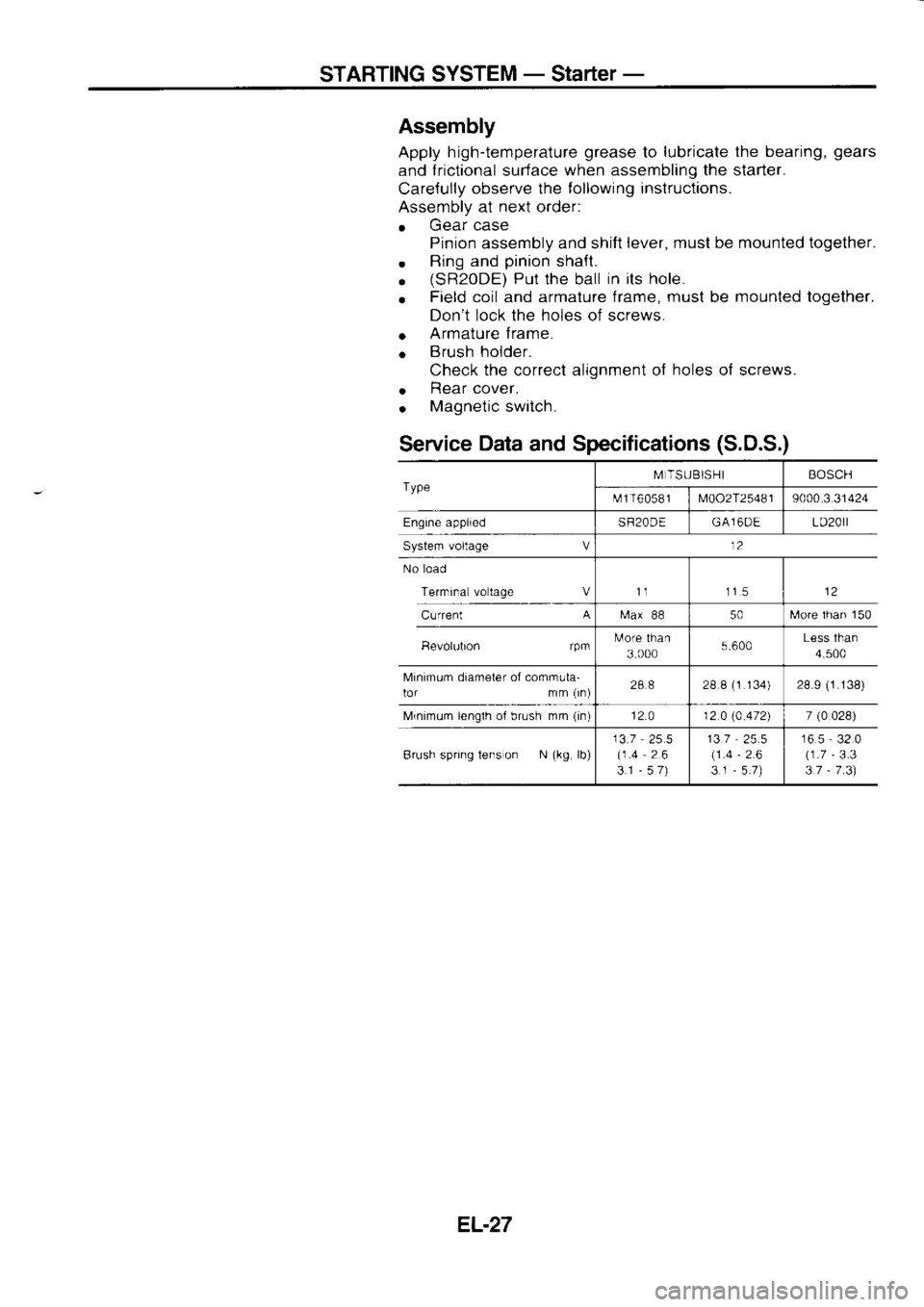
Service Data
and Specifications (S.D.S.)
Type M
TSUBISHI BOSCH
t\.rf 1 T6
05 8 I
M002T25481 9000.3
31424
Engine applied SR20DEGA16DE LD20rl
System voltage V 12
No load
Terrnrna voltage Vt1 115
Current A
[ra.x
88 50[,,lore
lhan 150
Bevolubon rpmtulore
than
3 000 5.600Less
than
4,500
Minimum diameter of comrnula-
lor mm (rn) 288
28 8 (1
134) 28.9 (1.138)
Mrnimum lenglh of brush mm (in)
12.0 12 0 (4.472)
7 (0
028)
Brush spring tens on N (kg,
lb) 13.7
25.5
(1.4 26
3.1 -57) 137
(1 .4
3.1 -
2.6 16.5
32.0
(1.7 -
3.3
3.7 -
7 .3)
EL.27
Page 1160 of 1254
HEADLAMP
PUSH Io
\
_@. PUSH
lo Bulb
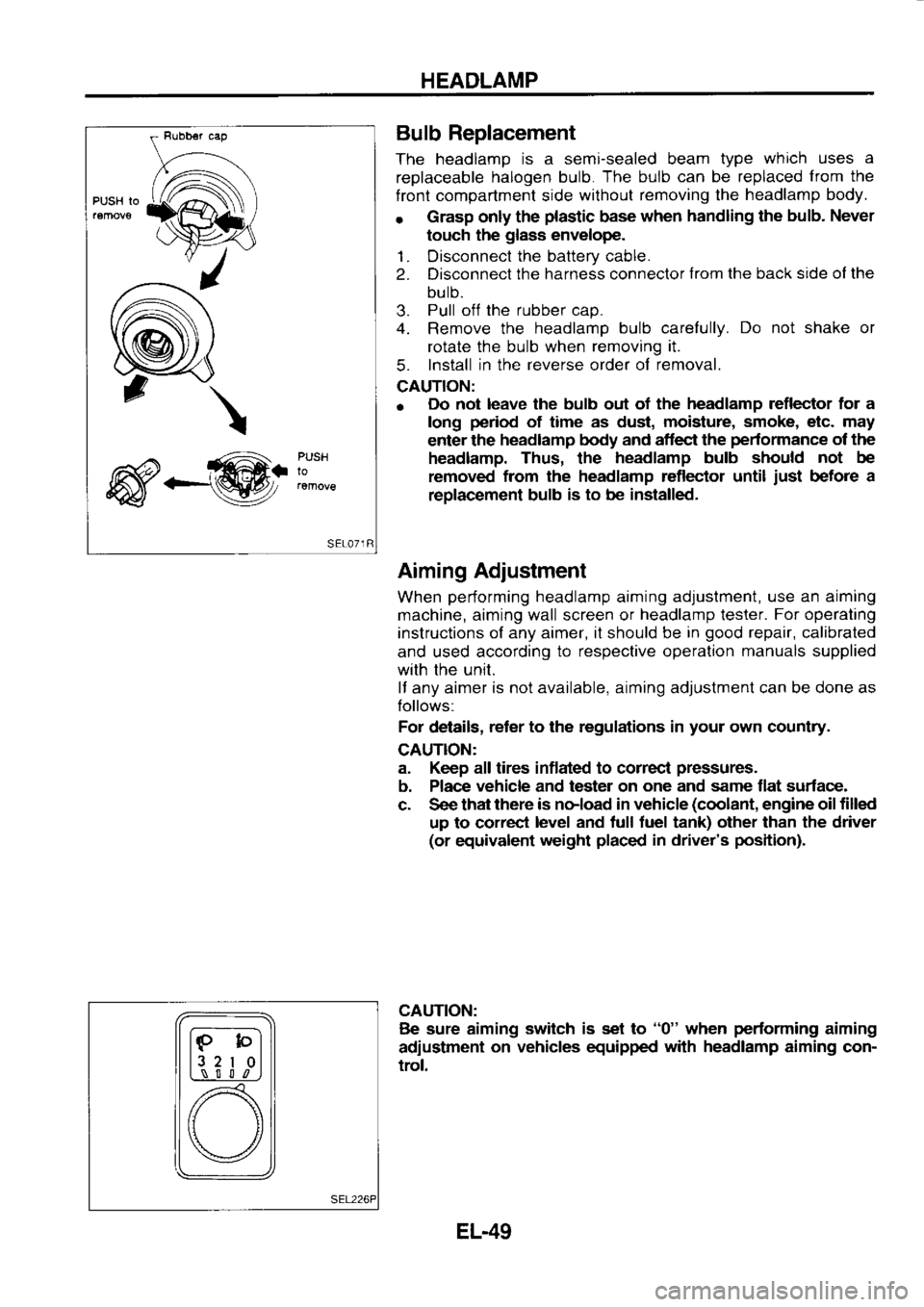
Replacement
The headlamp is
a semi-sealed beam type which
uses a
replaceable halogen
bulb. The
bulb can
be replaced from
the
f ront compartment side without
removing the headlamp
body.
r Grasp
only the plastic
base when
handling the bulb.
Never
touch the glass
envelope.
1. Disconnect the
battery cable.
2. Disconnect the
harness connector from
the back side ol the
bulb.
3. Pull
off the
rubber cap.
4. Remove the headlamp
bulb carefully. Do
not shake or
rotate the bulb when removing it.
5. Install
in the reverse
order of removal.
CAUTION:
o Do
not leave the bulb out of the headlamp
reflector for a
long period
of time as dust, moisture,
smoke, etc. may
enter the headlamp
body and aflect the pedormance
of the
headlamp. Thus, the headlamp
bulb should not
be
removed from
the headlamp reflector until just
before a
replac€ment bulb is
to be installed.
Aiming Adjustment
When performing
headlamp aiming adjustment, use
an aiming
machine, aiming wall screen or headlamp
lester. For
operating
instructions of any aimer, it should be in good
repair, calibrated
and used according to
respective operation manuals
supplied
with the unit.
lf any aimer is
not available, aiming adjustment can be done as
Iollows:
For details, reter
to the regulations in your
own country.
CAUTION:
a. Keep all tires inflated to correcl pressures.
b. Place vehicle
and tester on one
and same flat surface-
c. See that there
is noload in vehicle (coolant,
engine oil filled
up to correct level
and tull tuel tank) other than the driver
(or equivalent weight placed
in driver's position).
CAUTION: Be sure aiming switch
is set to "0"
when performing
aiming
adiustment on
vehicles equipped with
headlamp
aiming con-
trol.
lF-bl
l3 2
I 0l
L,\_-! S l l
,n
[) \/
EL-49
Page 1190 of 1254

WARNING
LAMPS AND
BUZZER
----](-
Continuity
Bsnery Diode
Check
o Check
continuity using an ohmmeter.
o Diode
is functioning properly
il test results are as shown in
the f
ioure
at left.
o Diodes
for warning lamps are built into the combination
meter orinted circuit.
Refer to "Combination
Meter".
Engine Oil Level Unit
Check
1 . Connect as shown in the figure at left.
2. lf test lamp comes on when disconnecting terminal
O from
battery ground,
engine oil level
unit is
normal.
Warning Buzer
Check
F \zz
fi*ffi=l
| | r:
rL----rr l
#/\
EL-79