change wheel NISSAN TEANA 2008 User Guide
[x] Cancel search | Manufacturer: NISSAN, Model Year: 2008, Model line: TEANA, Model: NISSAN TEANA 2008Pages: 5121, PDF Size: 69.03 MB
Page 2443 of 5121
FRONT DRIVE SHAFT BOOT
FAX-15
< ON-VEHICLE REPAIR >
C
E
F
G
H
I
J
K
L
MA
B
FA X
N
O
P
20. Install wheel sensor and sensor harness to steering knuckle. Refer to BRC-57, "FRONT WHEEL SEN-
SOR : Exploded View" (without VDC), BRC-151, "FRONT WHEEL SENSOR : Exploded View" (with
VDC).
TRANSAXLE SIDE
TRANSAXLE SIDE : Removal and InstallationINFOID:0000000003811081
Remove boot after removing drive shaft.
Remove: refer to FAX-18, "
LEFT SIDE : Removal and Installation" (left side), FAX-19, "RIGHT SIDE :
Removal and Installation" (right side).
Disassembly: refer to FAX-22, "
TRANSAXLE SIDE : Disassembly and Assembly".
InspectionINFOID:0000000003811082
INSPECTION AFTER REMOVAL
Move joint up/down, left/right, and in the axial directions. Check for motion that is not smooth and for signifi-
cant looseness.
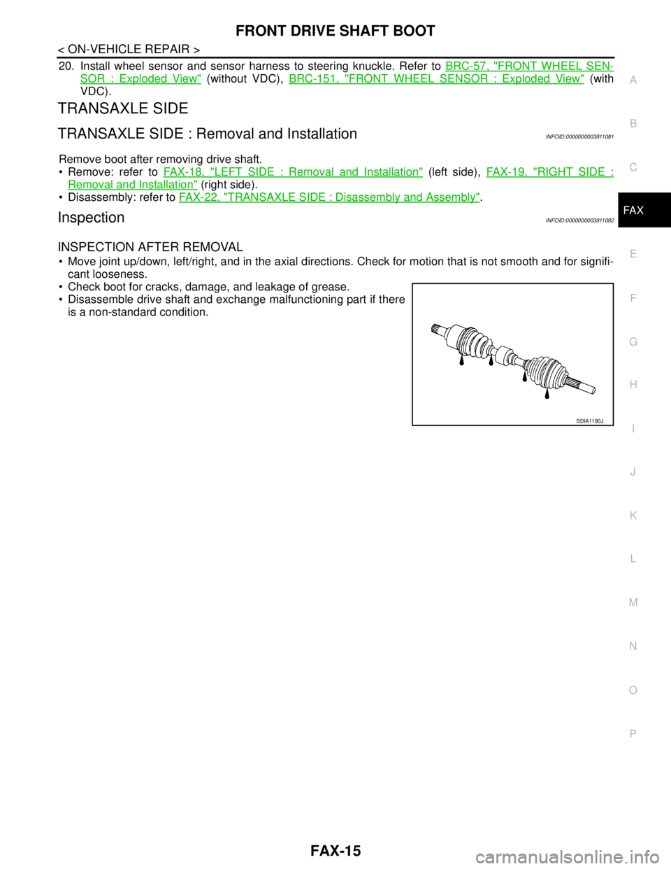
Check boot for cracks, damage, and leakage of grease.
Disassemble drive shaft and exchange malfunctioning part if there
is a non-standard condition.
SDIA1190J
Page 2462 of 5121
FAX-34
< ON-VEHICLE REPAIR >
FRONT DRIVE SHAFT
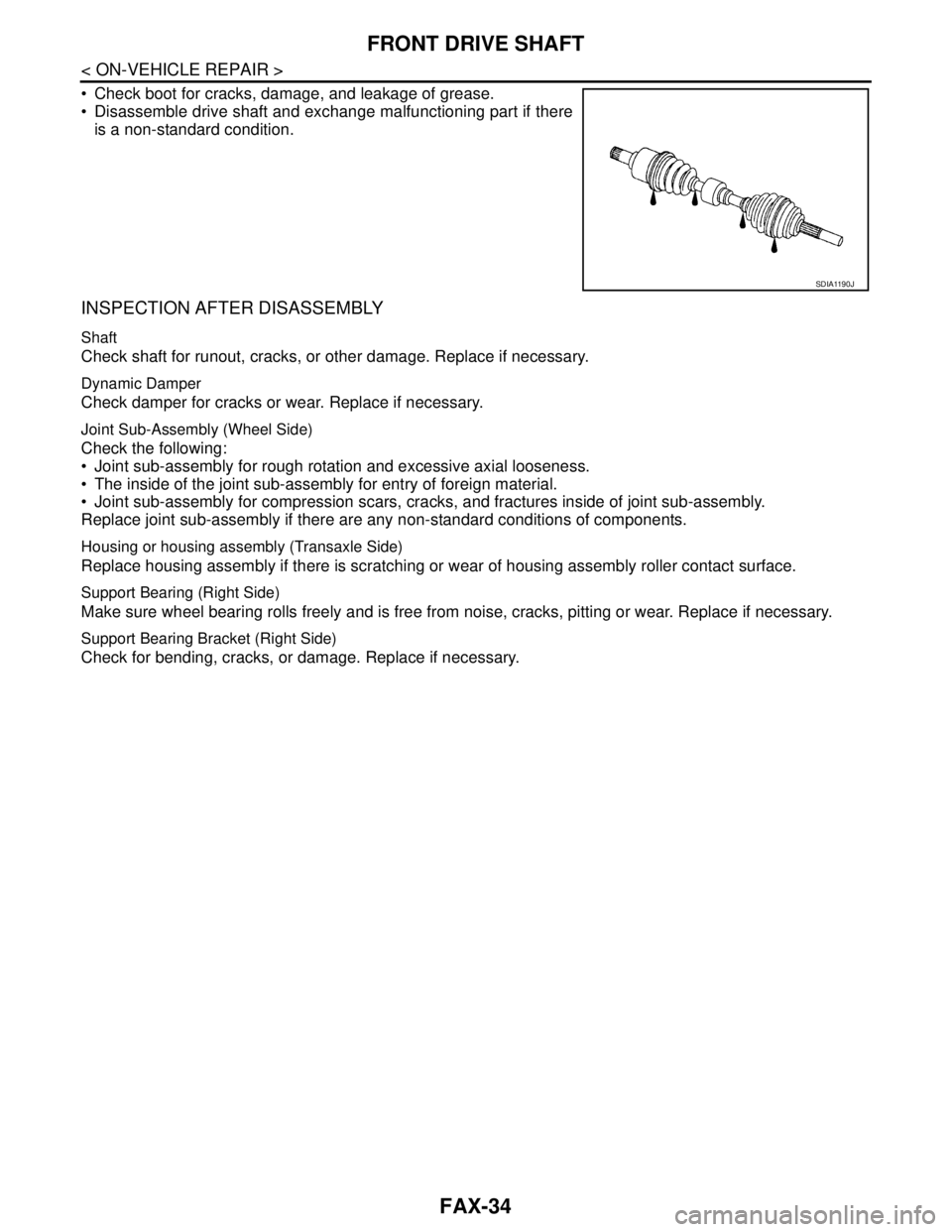
Check boot for cracks, damage, and leakage of grease.
Disassemble drive shaft and exchange malfunctioning part if there
is a non-standard condition.
INSPECTION AFTER DISASSEMBLY
Shaft
Check shaft for runout, cracks, or other damage. Replace if necessary.
Dynamic Damper
Check damper for cracks or wear. Replace if necessary.
Joint Sub-Assembly (Wheel Side)
Check the following:
Joint sub-assembly for rough rotation and excessive axial looseness.
The inside of the joint sub-assembly for entry of foreign material.
Joint sub-assembly for compression scars, cracks, and fractures inside of joint sub-assembly.
Replace joint sub-assembly if there are any non-standard conditions of components.
Housing or housing assembly (Transaxle Side)
Replace housing assembly if there is scratching or wear of housing assembly roller contact surface.
Support Bearing (Right Side)
Make sure wheel bearing rolls freely and is free from noise, cracks, pitting or wear. Replace if necessary.
Support Bearing Bracket (Right Side)
Check for bending, cracks, or damage. Replace if necessary.
SDIA1190J
Page 2523 of 5121
GI-30
< PRECAUTION >
LIFTING POINT
LIFTING POINT
Commercial Service ToolsINFOID:0000000003852788
CAUTION:
Every time the vehicle is lifted up, maintain the complete vehicle curb condition.
Since the vehicle's center of gravity changes when removing main parts on the front side (engine,
transmission, suspension etc.), support a jack up point on the rear side garage jack with a mission
jack or equivalent.
Since the vehicle's center of gravity changes when removing main parts on the rear side (rear axle,
suspension, etc.), support a jack up point on the front side garage jack with a mission jack or equiv-
alent.
Be careful not to smash or do not do anything that would affect piping parts.
Garage Jack and Safety Stand and 2-Pole LiftINFOID:0000000003852789
WARNING:
Park the vehicle on a level surface when using the jack. Make sure to avoid damaging pipes, tubes,
etc. under the vehicle.
Never get under the vehicle while it is supported only by the jack. Always use safety stands when
you have to get under the vehicle.
Place wheel chocks at both front and back of the wheels on the ground.
When lifting the vehicle, open the lift arms as wide as possible and ensure that the front and rear of
the vehicle are well balanced.
When setting the lift arm, do not allow the arm to contact the brake tubes, brake cable, fuel lines and
sill spoiler.
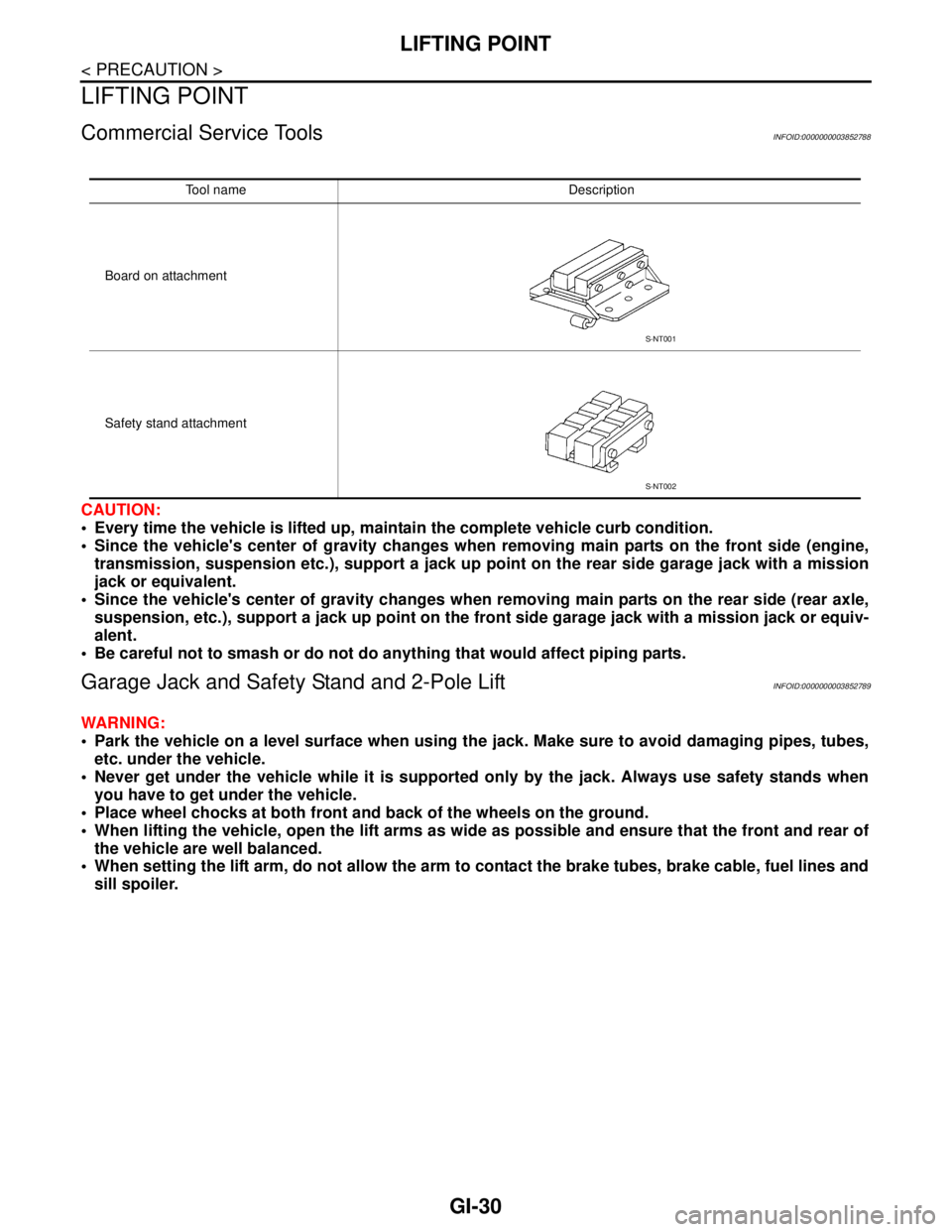
Tool name Description
Board on attachment
Safety stand attachment
S-NT001
S-NT002
Page 2525 of 5121
GI-32
< PRECAUTION >
TOW TRUCK TOWING
TOW TRUCK TOWING
Tow Truck TowingINFOID:0000000003852791
CAUTION:
All applicable state or Provincial laws and local laws regarding the towing operation must be
obeyed.
It is necessary to use proper towing equipment to avoid possible damage to the vehicle during tow-
ing operation. Towing is in accordance with Towing Procedure Manual at dealer.
Always attach safety chains before towing.
When towing, make sure that the transaxle, steering system and powertrain are in good order. If any
unit is damaged, dollies must be used.
Never tow a CVT model with the rear wheels raised and the front wheels on the ground. This may
cause serious and expensive damage to the transaxle. If it is necessary to tow the vehicle with the
rear wheels raised, always use towing dollies under the front wheels.
Never tow an automatic transaxle model from the rear (that is backward) with four wheels on the
ground. This may cause serious and expensive damage to the transaxle.
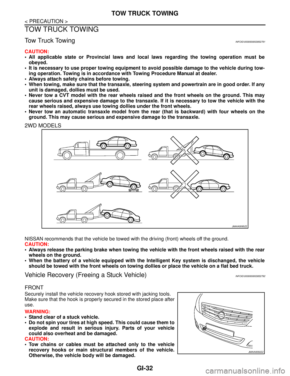
2WD MODELS
NISSAN recommends that the vehicle be towed with the driving (front) wheels off the ground.
CAUTION:
Always release the parking brake when towing the vehicle with the front wheels raised with the rear
wheels on the ground.
When the battery of a vehicle equipped with the Intelligent Key system is dischanged, the vehicle
should be towed with the front wheels on towing dollies or place the vehicle on a flat bed truck.
Vehicle Recovery (Freeing a Stuck Vehicle)INFOID:0000000003852792
FRONT
Securely install the vehicle recovery hook stored with jacking tools.
Make sure that the hook is properly secured in the stored place after
use.
WARNING:
Stand clear of a stuck vehicle.
Do not spin your tires at high speed. This could cause them to
explode and result in serious injury. Parts of your vehicle
could also overheat and be damaged.
CAUTION:
Tow chains or cables must be attached only to the vehicle
recovery hooks or main structural members of the vehicle.
Otherwise, the vehicle body will be damaged.
JMAIA0095ZZ
JMAIA0092ZZ
Page 3193 of 5121
GENERAL MAINTENANCE
MA-5
< ON-VEHICLE MAINTENANCE >
C
D
E
F
G
H
I
J
K
L
MB
MAN
OA
ON-VEHICLE MAINTENANCE
GENERAL MAINTENANCE
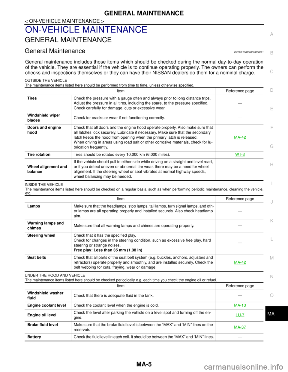
General MaintenanceINFOID:0000000003858221
General maintenance includes those items which should be checked during the normal day-to-day operation
of the vehicle. They are essential if the vehicle is to continue operating properly. The owners can perform the
checks and inspections themselves or they can have their NISSAN dealers do them for a nominal charge.
OUTSIDE THE VEHICLE
The maintenance items listed here should be performed from time to time, unless otherwise specified.
INSIDE THE VEHICLE
The maintenance items listed here should be checked on a regular basis, such as when performing periodic maintenance, cleaning the vehicle,
etc.
UNDER THE HOOD AND VEHICLE
The maintenance items listed here should be checked periodically e.g. each time you check the engine oil or refuel.
Item Reference page
TiresCheck the pressure with a gauge often and always prior to long distance trips.
Adjust the pressure in all tires, including the spare, to the pressure specified.
Check carefully for damage, cuts or excessive wear.—
Windshield wiper
bladesCheck for cracks or wear if not functioning correctly. —
Doors and engine
hoodCheck that all doors and the engine hood operate properly. Also make sure that
all latches lock securely. Lubricate if necessary. Make sure that the secondary
latch keeps the hood from opening when the primary latch is released.
When driving in areas using road salt or other corrosive materials, check for lu-
brication frequently.MA-42
Tire rotationTires should be rotated every 10,000 km (6,000 miles).WT-3
Wheel alignment and
balanceIf the vehicle should pull to either side while driving on a straight and level road,
or if you detect uneven or abnormal tire wear. there may be a need for wheel
alignment. If the steering wheel or seat vibrates at normal highway speeds,
wheel balancing may be needed.
Item Reference page
LampsMake sure that the headlamps, stop lamps, tail lamps, turn signal lamps, and oth-
er lamps are all operating properly and installed securely. Also check headlamp
aim.—
Warning lamps and
chimesMake sure that all warning lamps and chimes are operating properly. —
Steering wheelCheck that it has the specified play.
Check for changes in the steering condition, such as excessive free play, hard
steering or strange noises.
Free play: Less than 35 mm (1.38 in)—
Seat beltsCheck that all parts of the seat belt system (e.g. buckles, anchors, adjusters and
retractors) operate properly and smoothly, and are installed securely. Check the
belt webbing for cuts, fraying, wear or damage.MA-42
Item Reference page
Windshield washer
fluidCheck that there is adequate fluid in the tank. —
Engine coolant levelCheck the coolant level when the engine is cold.MA-13
Engine oil levelCheck the level after parking the vehicle on a level spot and turning off the en-
gine.LU-7
Brake fluid levelMake sure that the brake fluid level is between the “MAX” and “MIN” lines on the
reservoir.MA-37
BatteryCheck the fluid level in each cell. It should be between the “MAX” and “MIN” lines. —
Page 3232 of 5121
MA-44
< SERVICE DATA AND SPECIFICATIONS (SDS)
SERVICE DATA AND SPECIFICATIONS (SDS)
SERVICE DATA AND SPECIFICATIONS (SDS)
SERVICE DATA AND SPECIFICATIONS (SDS)
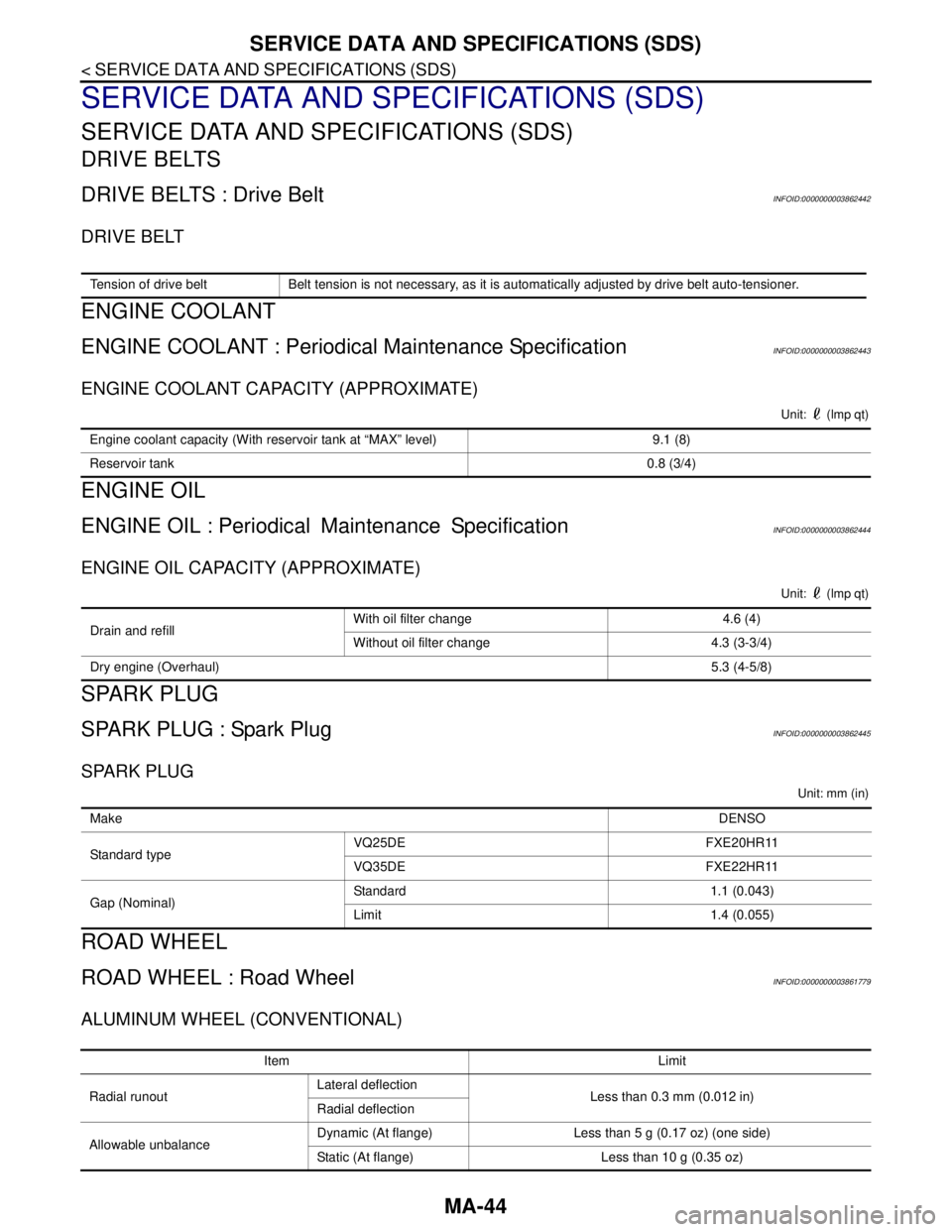
DRIVE BELTS
DRIVE BELTS : Drive BeltINFOID:0000000003862442
DRIVE BELT
ENGINE COOLANT
ENGINE COOLANT : Periodical Maintenance SpecificationINFOID:0000000003862443
ENGINE COOLANT CAPACITY (APPROXIMATE)
Unit: (lmp qt)
ENGINE OIL
ENGINE OIL : PeriodicalMaintenance SpecificationINFOID:0000000003862444
ENGINE OIL CAPACITY (APPROXIMATE)
Unit: (lmp qt)
SPARK PLUG
SPARK PLUG : Spark PlugINFOID:0000000003862445
SPARK PLUG
Unit: mm (in)
ROAD WHEEL
ROAD WHEEL : Road WheelINFOID:0000000003861779
ALUMINUM WHEEL (CONVENTIONAL)
Tension of drive belt Belt tension is not necessary, as it is automatically adjusted by drive belt auto-tensioner.
Engine coolant capacity (With reservoir tank at “MAX” level) 9.1 (8)
Reservoir tank0.8 (3/4)
Drain and refill With oil filter change 4.6 (4)
Without oil filter change 4.3 (3-3/4)
Dry engine (Overhaul)5.3 (4-5/8)
MakeDENSO
Standard typeVQ25DE FXE20HR11
VQ35DE FXE22HR11
Gap (Nominal)Standard 1.1 (0.043)
Limit 1.4 (0.055)
Item Limit
Radial runoutLateral deflection
Less than 0.3 mm (0.012 in)
Radial deflection
Allowable unbalanceDynamic (At flange) Less than 5 g (0.17 oz) (one side)
Static (At flange) Less than 10 g (0.35 oz)
Page 4492 of 5121

MECHANICAL SYSTEM
TM-19
< FUNCTION DIAGNOSIS >[CVT: RE0F09B]
C
E
F
G
H
I
J
K
L
MA
B
TM
N
O
P
CVT fluid temperature sensor
Secondary pressure sensor
ROM assembly
Component DescriptionINFOID:0000000003848923
Item Function
Torque converterThe torque converter is the device that increases the engine torque as well as the con-
ventional AT and transmits it to the transaxle.
Oil pumpThe adoption of a trochoidal oil pump with a flow control valve actuated directly by the
engine enables the sufficient discharge from an oil pump in the low-rpm range and the
adequate discharge adjustments in the high-rpm range.
Planetary gear
Perform the transmission of drive power and the switching of forward/backward move-
ment. Forward clutch
Reverse brake
Primary pulley It is composed of a pair of pulleys (the groove width is changed freely in the axial direc-
tion) and the steel belt (the steel star wheels are placed continuously and the belt is guid-
ed with the multilayer steel rings on both sides). The groove width changes according to
wrapping radius of steel belt and pulley from low status to overdrive status continuously
with non-step. It is controlled with the oil pressures of primary pulley and secondary pul-
ley. Secondary pulley
Steel belt
Output gear
Reduction gear consists of primary deceleration (output gear and idler gear in pair) and
secondary deceleration (reduction gear and final gear in pair). Each of them uses a he-
lical gear. Idler gear
Reduction gear
Final gear
Differential
Manual shaft
The parking rod rotates the parking pole and the parking pole engages with the parking
gear when the manual shaft is in “P” position. As a result the parking gear and the output
axis are fixed. Parking rod
Parking pawl
Parking gear
Page 4659 of 5121

TM-186
< FUNCTION DIAGNOSIS >[CVT: RE0F10A]
MECHANICAL SYSTEM
Component Description
INFOID:0000000003806353
Item Function
Torque converterThe torque converter is the device that increases the engine torque as well as the conventional
CVT and transmits it to the transaxle.
Oil pumpThe efficiency of pump discharge rate has been increased at low-rpm and optimized at high-rpm
by adopting a vane-type oil pump controlled by the engine. Discharged oil from oil pump is trans-
mitted to the control valve. It is used as the oil of primary and secondary pulley operation and the
oil of clutch operation and the lubricant for each part.
Planetary gear
Perform the transmission of drive power and the switching of forward/backward movement. Forward clutch
Reverse brake
Primary pulley It is composed of a pair of pulleys (the groove width is changed freely in the axial direction) and
the steel belt (the steel star wheels are placed continuously and the belt is guided with the mul-
tilayer steel rings on both sides). The groove width changes according to wrapping radius of steel
belt and pulley from low status to overdrive status continuously with non-step. It is controlled with
the oil pressures of primary pulley and secondary pulley. Secondary pulley
Steel belt
Output gear
Reduction gear consists of primary deceleration (output gear and idler gear in pair) and second-
ary deceleration (reduction gear and final gear in pair). Each of them uses a helical gear. Idler gear
Reduction gear
Final gear
Differential
Manual shaft
The parking rod rotates the parking pole and the parking pole engages with the parking gear
when the manual shaft is in P position. As a result the parking gear and the output axis are fixed. Parking rod
Parking pawl
Parking gear