heater NISSAN TEANA 2008 Workshop Manual
[x] Cancel search | Manufacturer: NISSAN, Model Year: 2008, Model line: TEANA, Model: NISSAN TEANA 2008Pages: 5121, PDF Size: 69.03 MB
Page 2613 of 5121
HA-44
< ON-VEHICLE REPAIR >
HIGH-PRESSURE PIPE
HIGH-PRESSURE PIPE
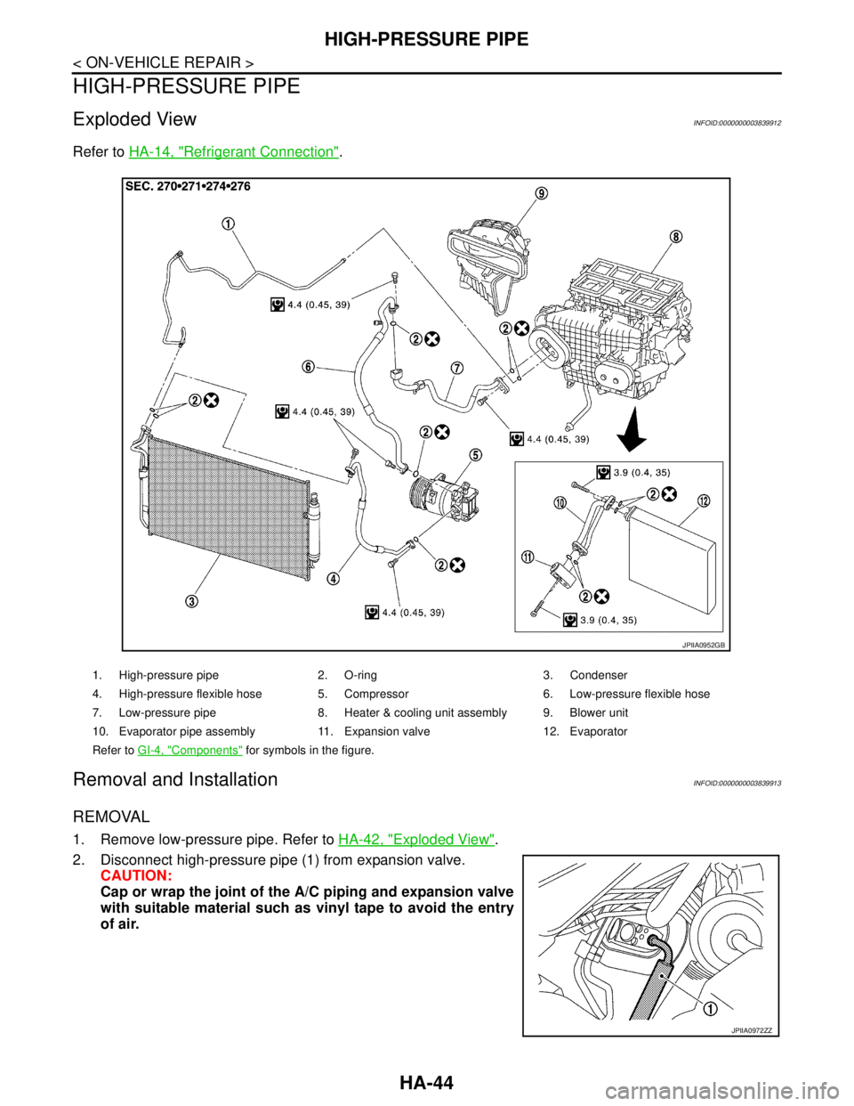
Exploded ViewINFOID:0000000003839912
Refer to HA-14, "Refrigerant Connection".
Removal and InstallationINFOID:0000000003839913
REMOVAL
1. Remove low-pressure pipe. Refer to HA-42, "Exploded View".
2. Disconnect high-pressure pipe (1) from expansion valve.
CAUTION:
Cap or wrap the joint of the A/C piping and expansion valve
with suitable material such as vinyl tape to avoid the entry
of air.
1. High-pressure pipe 2. O-ring 3. Condenser
4. High-pressure flexible hose 5. Compressor 6. Low-pressure flexible hose
7. Low-pressure pipe 8. Heater & cooling unit assembly 9. Blower unit
10. Evaporator pipe assembly 11. Expansion valve 12. Evaporator
Refer to GI-4, "
Components" for symbols in the figure.
JPIIA0952GB
JPIIA0972ZZ
Page 2621 of 5121
HA-52
< ON-VEHICLE REPAIR >
EVAPORATOR
EVAPORATOR
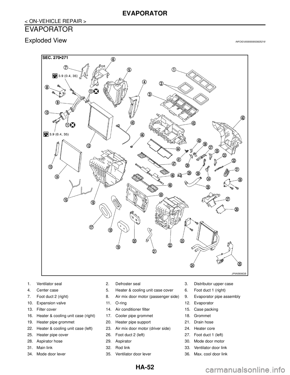
Exploded ViewINFOID:0000000003825218
1. Ventilator seal 2. Defroster seal 3. Distributor upper case
4. Center case 5. Heater & cooling unit case cover 6. Foot duct 1 (right)
7. Foot duct 2 (right) 8. Air mix door motor (passenger side) 9. Evaporator pipe assembly
10. Expansion valve 11. O-ring 12. Evaporator
13. Filter cover 14. Air conditioner filter 15. Case packing
16. Heater & cooling unit case (right) 17. Cooler pipe grommet 18. Grommet
19. Heater pipe grommet 20. Heater pipe support 21. Drain hose
22. Heater & cooling unit case (left) 23. Air mix door motor (driver side) 24. Heater core
25. Heater pipe cover 26. Foot duct 2 (left) 27. Foot duct 1 (left)
28. Aspirator hose 29. Aspirator 30. Mode door motor
31. Main link 32. Rod link 33. Ventilator door link
34. Mode door lever 35. Ventilator door lever 36. Max. cool door link
JPIIA0906GB
Page 2623 of 5121
HA-54
< ON-VEHICLE REPAIR >
EVAPORATOR PIPE ASSEMBLY
EVAPORATOR PIPE ASSEMBLY
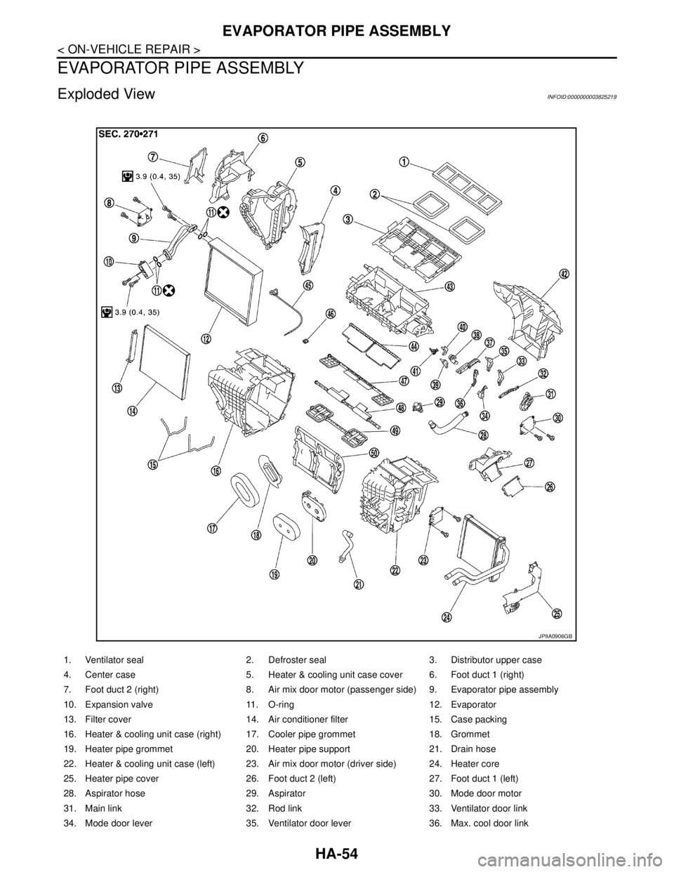
Exploded ViewINFOID:0000000003825219
1. Ventilator seal 2. Defroster seal 3. Distributor upper case
4. Center case 5. Heater & cooling unit case cover 6. Foot duct 1 (right)
7. Foot duct 2 (right) 8. Air mix door motor (passenger side) 9. Evaporator pipe assembly
10. Expansion valve 11. O-ring 12. Evaporator
13. Filter cover 14. Air conditioner filter 15. Case packing
16. Heater & cooling unit case (right) 17. Cooler pipe grommet 18. Grommet
19. Heater pipe grommet 20. Heater pipe support 21. Drain hose
22. Heater & cooling unit case (left) 23. Air mix door motor (driver side) 24. Heater core
25. Heater pipe cover 26. Foot duct 2 (left) 27. Foot duct 1 (left)
28. Aspirator hose 29. Aspirator 30. Mode door motor
31. Main link 32. Rod link 33. Ventilator door link
34. Mode door lever 35. Ventilator door lever 36. Max. cool door link
JPIIA0906GB
Page 2624 of 5121
EVAPORATOR PIPE ASSEMBLY
HA-55
< ON-VEHICLE REPAIR >
C
D
E
F
G
H
J
K
L
MA
B
HA
N
O
P
Removal and InstallationINFOID:0000000003795853
REMOVAL
1. Disconnect the battery cable from the negative terminal after setting the temperature (passenger side) to
18°C (60°F).
2. Use refrigerant collecting equipment (for HFC-134a) to discharge the refrigerant.
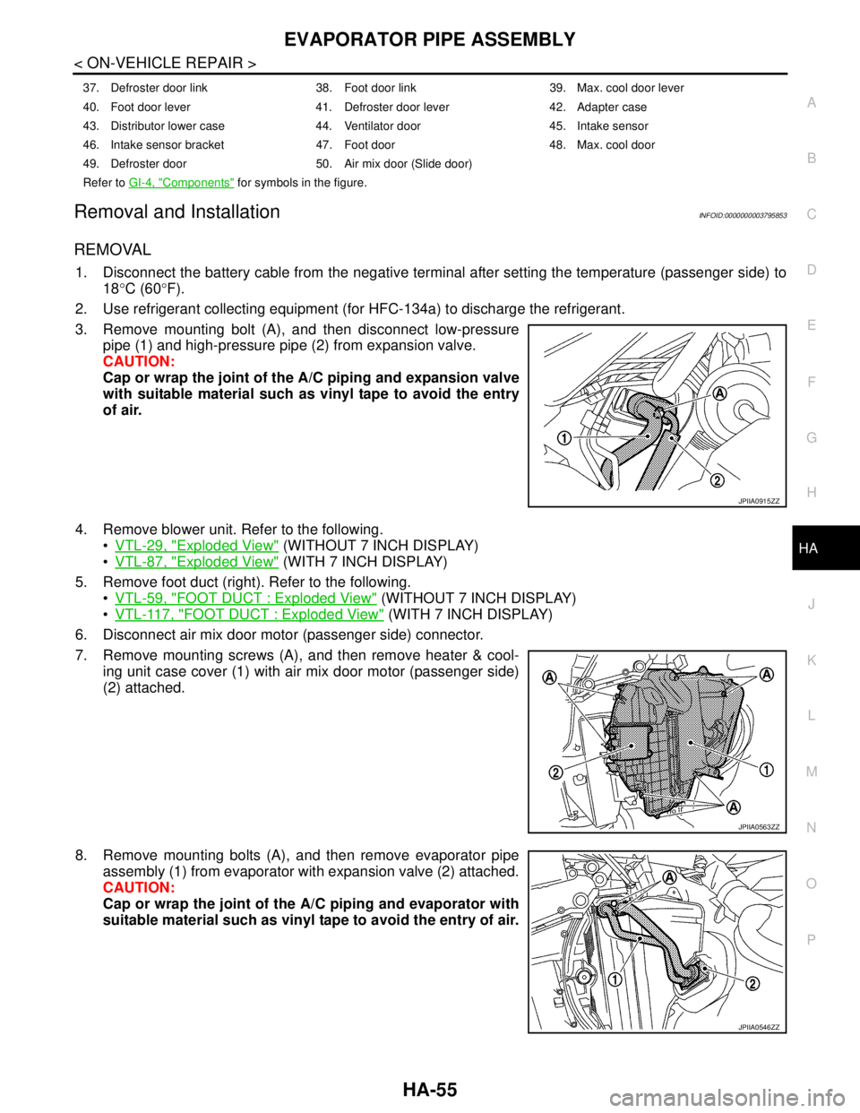
3. Remove mounting bolt (A), and then disconnect low-pressure
pipe (1) and high-pressure pipe (2) from expansion valve.
CAUTION:
Cap or wrap the joint of the A/C piping and expansion valve
with suitable material such as vinyl tape to avoid the entry
of air.
4. Remove blower unit. Refer to the following.
VTL-29, "
Exploded View" (WITHOUT 7 INCH DISPLAY)
VTL-87, "
Exploded View" (WITH 7 INCH DISPLAY)
5. Remove foot duct (right). Refer to the following.
VTL-59, "
FOOT DUCT : Exploded View" (WITHOUT 7 INCH DISPLAY)
VTL-117, "
FOOT DUCT : Exploded View" (WITH 7 INCH DISPLAY)
6. Disconnect air mix door motor (passenger side) connector.
7. Remove mounting screws (A), and then remove heater & cool-
ing unit case cover (1) with air mix door motor (passenger side)
(2) attached.
8. Remove mounting bolts (A), and then remove evaporator pipe
assembly (1) from evaporator with expansion valve (2) attached.
CAUTION:
Cap or wrap the joint of the A/C piping and evaporator with
suitable material such as vinyl tape to avoid the entry of air.
37. Defroster door link 38. Foot door link 39. Max. cool door lever
40. Foot door lever 41. Defroster door lever 42. Adapter case
43. Distributor lower case 44. Ventilator door 45. Intake sensor
46. Intake sensor bracket 47. Foot door 48. Max. cool door
49. Defroster door 50. Air mix door (Slide door)
Refer to GI-4, "
Components" for symbols in the figure.
JPIIA0915ZZ
JPIIA0563ZZ
JPIIA0546ZZ
Page 2626 of 5121

EXPANSION VALVE
HA-57
< ON-VEHICLE REPAIR >
C
D
E
F
G
H
J
K
L
MA
B
HA
N
O
P
EXPANSION VALVE
Exploded ViewINFOID:0000000003825220
1. Ventilator seal 2. Defroster seal 3. Distributor upper case
4. Center case 5. Heater & cooling unit case cover 6. Foot duct 1 (right)
7. Foot duct 2 (right) 8. Air mix door motor (passenger side) 9. Evaporator pipe assembly
10. Expansion valve 11. O-ring 12. Evaporator
13. Filter cover 14. Air conditioner filter 15. Case packing
16. Heater & cooling unit case (right) 17. Cooler pipe grommet 18. Grommet
19. Heater pipe grommet 20. Heater pipe support 21. Drain hose
22. Heater & cooling unit case (left) 23. Air mix door motor (driver side) 24. Heater core
25. Heater pipe cover 26. Foot duct 2 (left) 27. Foot duct 1 (left)
28. Aspirator hose 29. Aspirator 30. Mode door motor
31. Main link 32. Rod link 33. Ventilator door link
34. Mode door lever 35. Ventilator door lever 36. Max. cool door link
JPIIA0906GB
Page 2629 of 5121
HAC-1
VENTILATION, HEATER & AIR CONDITIONER
C
DE
F
G H
J
K L
M
SECTION HAC
A
B
HAC
N
O P
CONTENTS
HEATER & AIR CONDITIONING CONTROL SYSTEM
WITHOUT 7 INCH DISPLAY
BASIC INSPECTION ....... .............................
6
DIAGNOSIS AND REPAIR WORKFLOW ..... .....6
Work Flow ........................................................... ......6
INSPECTION AND ADJUSTMENT .....................8
Description & Inspection ..................................... ......8
Temperature Setting Trimmer .................................10
Foot Position Setting Trimmer .................................10
Inlet Port Memory Function (FRE) ..........................11
Inlet Port Memory Function (REC) ..........................11
FUNCTION DIAGNOSIS ..............................12
COMPRESSOR CONTROL FUNCTION ........ ....12
Description .......................................................... ....12
Fail-Safe ..................................................................13
Component Part Location .......................................13
Component’s Role ...................................................15
AUTOMATIC AIR CONDITIONER SYSTEM .....17
System Diagram .................................................. ....17
System Description .................................................17
Component Part Location .......................................24
Component Description ...........................................26
MODE DOOR CONTROL SYSTEM ...................28
System Diagram .................................................. ....28
System Description .................................................28
AIR MIX DOOR CONTROL SYSTEM ................30
System Diagram .................................................. ....30
System Description .................................................30
INTAKE DOOR CONTROL SYSTEM ................32
System Diagram .................................................. ....32
System Description .................................................32
BLOWER MOTOR CONTROL SYSTEM ...........34
System Diagram .................................................. ....34
System Description .................................................34
MAGNET CLUTCH CONTROL SYSTEM .........36
System Diagram .................................................. ....36
System Description ..................................................36
CAN COMMUNICATION SYSTEM ...................37
System Description ..................................................37
DIAGNOSIS SYSTEM (HVAC) .........................38
CONSULT-III Function ............................................38
COMPONENT DIAGNOSIS .........................42
U1000 CAN COMM CIRCUIT ...........................42
Description ........................................................... ....42
DTC Logic ................................................................42
Diagnosis Procedure ..............................................42
U1010 CONTROL UNIT (CAN) .........................43
Description ...............................................................43
DTC Logic ................................................................43
Diagnosis Procedure ...............................................43
B257B, B257C AMBIENT SENSOR .................44
Description ...............................................................44
DTC Logic ................................................................44
Diagnosis Procedure ...............................................45
Component Inspection .............................................46
B2578, B2579 IN-VEHICLE SENSOR ..............47
Description ...............................................................47
DTC Logic ................................................................47
Diagnosis Procedure ...............................................48
Component Inspection .............................................49
B2581, B2582 INTAKE SENSOR .....................50
Description ...............................................................50
DTC Logic ................................................................50
Diagnosis Procedure ...............................................50
Component Inspection .............................................51
B2630, B2631 SUNLOAD SENSOR .................53
Description ...............................................................53
Page 2675 of 5121

B2578, B2579 IN-VEHICLE SENSOR
HAC-47
< COMPONENT DIAGNOSIS >[WITHOUT 7 INCH DISPLAY]
C
D
E
F
G
H
J
K
L
MA
B
HAC
N
O
P
B2578, B2579 IN-VEHICLE SENSOR
DescriptionINFOID:0000000003846332
In-vehicle Sensor
The in-vehicle sensor (1) is located on instrument driver lower
panel.
It converts variations in compartment air temperature drawn from
the aspirator into a resistance value. It is then input into the A/C
auto amp.
In-vehicle Sensor Circuit
Aspirator
The aspirator (1) is located on driver side of heater & cooling unit
assembly. It produces vacuum pressure due to air discharged from
the heater & cooling unit assembly, continuously taking compartment
air in the aspirator.
DTC LogicINFOID:0000000003846333
DTC DETECTION LOGIC
NOTE:
JPIIA1019ZZ
JPIIA0613GB
:Vehicle front
JPIIA0890ZZ
RJIA1804E
Page 2684 of 5121

HAC-56
< COMPONENT DIAGNOSIS >[WITHOUT 7 INCH DISPLAY]
B2632, B2633 AIR MIX DOOR MOTOR (DRIVER SIDE)
B2632, B2633 AIR MIX DOOR MOTOR (DRIVER SIDE)
DescriptionINFOID:0000000003846347
COMPONENT DESCRIPTION
Air Mix Door Motor (Driver Side)
The air mix door motor (driver side) (1) are attached to the heater
& cooling unit assembly.
It rotates so that the air mix door is opened or closed to a position
set by the A/C auto amp.
Motor rotation is then conveyed through a shaft and the air mix
door position feedback is then sent to the A/C auto amp. by PBR
built-in air mix door motor.
DTC LogicINFOID:0000000003846348
DTC DETECTION LOGIC
NOTE:
If DTC is displayed along with DTC U1000 or U1010, first diagnose the DTC U1000 or U1010. Refer to HAC-
42, "DTC Logic" or HAC-43, "DTC Logic".
DTC CONFIRMATION PROCEDURE
1.CHECK WITH SELF-DIAGNOSIS FUNCTION OF CONSULT-III
1. Using CONSULT-III, perform “SELF-DIAGNOSIS RESULTS” of HVAC.
2. Check if any DTC is displayed in the self-diagnosis results.
NOTE:
If DTC is displayed along with DTC U1000 or U1010, first diagnose the DTC U1000 or U1010. Refer to HAC-
42, "DTC Logic" or HAC-43, "DTC Logic".
Is DTC
“B2632” or “B2633” displayed?
YES >> Perform trouble diagnosis for the air mix door motor (driver side). Refer to HAC-57, "Diagnosis
Procedure".
NO >> GO TO 2.
2.FUNCTION INSPECTION
1. Press temperature control “UP” switch (driver side) until 32°C (90°F) is displayed.
2. Check for warm air at discharge air outlets.
3. Operate the compressor.
4. Press temperature control “DOWN” switch (driver side) until 18°C (60°F) is displayed.
5. Check for cool air at air discharge outlets.
Does it operate normally?
YES >> END.
NO >> Check air mix door motor (driver side) installation, and repair or replace the malfunctioning parts.
:Vehicle front
JPIIA0891ZZ
DTCItems
(CONSULT-III screen terms)Diagnostic item is detected when... Possible cause
B2632 DR AIRMIX ACTR (SHORT)Air mix door PBR (driver side) position
5% or less Air mix door motor (driver side)
A/C auto amp.
Harness and connector
(CAN communication line is
open or shorted)
(Air mix door motor is open or
shorted) B2633 DR AIRMIX ACTR (OPEN)Air mix door PBR (driver side) position
95% or more
Page 2686 of 5121

HAC-58
< COMPONENT DIAGNOSIS >[WITHOUT 7 INCH DISPLAY]
B2634, B2635 AIR MIX DOOR MOTOR (PASSENGER SIDE)
B2634, B2635 AIR MIX DOOR MOTOR (PASSENGER SIDE)
DescriptionINFOID:0000000003846350
COMPONENT DESCRIPTION
Air Mix Door Motor (Passenger Side)
The air mix door motor (passenger side) (1) are attached to the
heater & cooling unit assembly.
It rotates so that the air mix door is opened or closed to a position
set by the A/C auto amp.
Motor rotation is then conveyed through a shaft and the air mix
door position feedback is then sent to the A/C auto amp. by PBR
built-in air mix door motor.
DTC LogicINFOID:0000000003846351
DTC DETECTION LOGIC
NOTE:
If DTC is displayed along with DTC U1000 or U1010, first diagnose the DTC U1000 or U1010. Refer to HAC-
42, "DTC Logic" or HAC-43, "DTC Logic".
DTC CONFIRMATION PROCEDURE
1.CHECK WITH SELF-DIAGNOSIS FUNCTION OF CONSULT-III
1. Using CONSULT-III, perform “SELF-DIAGNOSIS RESULTS” of HVAC.
2. Check if any DTC is displayed in the self-diagnosis results.
NOTE:
If DTC is displayed along with DTC U1000 or U1010, first diagnose the DTC U1000 or U1010. Refer to HAC-
42, "DTC Logic" or HAC-43, "DTC Logic".
Is DTC
“B2634” or “B2635” displayed?
YES >> Perform trouble diagnosis for the air mix door motor (passenger side). Refer to HAC-59, "Diagno-
sis Procedure".
NO >> GO TO 2.
2.FUNCTION INSPECTION
1. Press temperature control “UP” switch (passenger side) until 32°C (90°F) is displayed.
2. Check for warm air at discharge air outlets.
3. Operate the compressor.
4. Press temperature control “DOWN” switch (passenger side) until 18°C (60°F) is displayed.
5. Check for cool air at air discharge outlets.
Does it operate normally?
YES >> END.
NO >> Check air mix door motor (passenger side) installation, and repair or replace the malfunctioning
parts.
:Vehicle front
JPIIA0892ZZ
DTCItems
(CONSULT-III screen terms)Diagnostic item is detected when... Possible cause
B2634 PASS AIRMIX ACTR (SHORT)Air mix door PBR (passenger side) position
5% or less Air mix door motor (passenger
side)
A/C auto amp.
Harness and connector
(CAN communication line is open
or shorted)
(Air mix door motor is open or
shorted) B2635 PASS AIRMIX ACTR (OPEN)Air mix door PBR (passenger side) position
95% or more
Page 2688 of 5121

HAC-60
< COMPONENT DIAGNOSIS >[WITHOUT 7 INCH DISPLAY]
B2636, B2637, B2638, B2639, B2654, B2655 MODE DOOR MOTOR
B2636, B2637, B2638, B2639, B2654, B2655 MODE DOOR MOTOR
DescriptionINFOID:0000000003846353
COMPONENT DESCRIPTION
Mode Door Motor
The mode door motor (1) are attached to the heater & cooling unit
assembly.
It rotates so that air is discharged from the outlet set by the A/C
auto amp. Motor rotation is conveyed to a link which activates the
mode door.
DTC LogicINFOID:0000000003846354
DTC DETECTION LOGIC
NOTE:
If DTC is displayed along with DTC U1000 or U1010, first diagnose the DTC U1000 or U1010. Refer to HAC-
42, "DTC Logic" or HAC-43, "DTC Logic".
DTC CONFIRMATION PROCEDURE
1.CHECK WITH SELF-DIAGNOSIS FUNCTION OF CONSULT-III
1. Using CONSULT-III, perform “SELF-DIAGNOSIS RESULTS” of HVAC.
2. Check if any DTC is displayed in the self-diagnosis results.
NOTE:
If DTC is displayed along with DTC U1000 or U1010, first diagnose the DTC U1000 or U1010. Refer to HAC-
42, "DTC Logic" or HAC-43, "DTC Logic".
Is DTC
“ B2636 ”, “ B2637 ”, “B2638 ”, “B2639 ”, “B2654 ” or “B2655 ” displayed?
YES >> Perform trouble diagnosis for the mode door motor. Refer to HAC-61, "Diagnosis Procedure".
NO >> GO TO 2.
2.FUNCTION INSPECTION
1. Press MODE switch and DEF switch.
2. Each position indicator should change shape.
:Vehicle front
JPIIA0893ZZ
DTCItems
(CONSULT-III screen terms)Diagnostic item is detected when... Possible cause
B2636 DR VENT DOOR FAILWhen the malfunctioning door position is
detected at VENT position
Mode door motor
A/C auto amp.
Harness and connector
(CAN communication line is open
or shorted)
(Mode door motor is open or short-
ed) B2637 DR B/L DOOR FAILWhen the malfunctioning door position is
detected at B/L position
B2638 DR D/F1 DOOR FAILWhen the malfunctioning door position is
detected at FOOT position
B2639 DR DEF DOOR FAILWhen the malfunctioning door position is
detected at DEF position
B2654 D/F2 DOOR FAILWhen the malfunctioning door position is
detected at D/F position
B2655 B/L2 DOOR FAILWhen the malfunctioning door position is
detected at B/L2 position