flat tire NISSAN TEANA 2008 Service Manual
[x] Cancel search | Manufacturer: NISSAN, Model Year: 2008, Model line: TEANA, Model: NISSAN TEANA 2008Pages: 5121, PDF Size: 69.03 MB
Page 2482 of 5121
FSU-8
< ON-VEHICLE MAINTENANCE >
WHEEL ALIGNMENT
Kingpin inclination angle is reference value, no inspection is required.
Toe-In
Measure toe-in by the following procedure.
WARNING:
Always perform the following procedure on a flat surface.
Make sure that no person is in front of vehicle before pushing it.
1. Bounce front of vehicle up and down to stabilize the vehicle height (posture).
2. Push vehicle straight ahead about 5 m (16 ft).
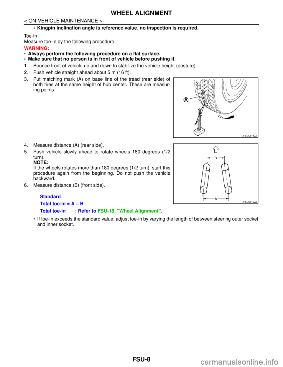
3. Put matching mark (A) on base line of the tread (rear side) of
both tires at the same height of hub center. These are measur-
ing points.
4. Measure distance (A) (rear side).
5. Push vehicle slowly ahead to rotate wheels 180 degrees (1/2
turn).
NOTE:
If the wheels rotates more than 180 degrees (1/2 turn), start this
procedure again from the beginning. Do not push the vehicle
backward.
6. Measure distance (B) (front side).
If toe-in exceeds the standard value, adjust toe-in by varying the length of between steering outer socket
and inner socket.
JPEIA0014ZZ
Standard
Total toe-in = A – B
Total toe-in : Refer to FSU-18, "
Wheel Alignment".
JPEIA0015ZZ
Page 2525 of 5121
GI-32
< PRECAUTION >
TOW TRUCK TOWING
TOW TRUCK TOWING
Tow Truck TowingINFOID:0000000003852791
CAUTION:
All applicable state or Provincial laws and local laws regarding the towing operation must be
obeyed.
It is necessary to use proper towing equipment to avoid possible damage to the vehicle during tow-
ing operation. Towing is in accordance with Towing Procedure Manual at dealer.
Always attach safety chains before towing.
When towing, make sure that the transaxle, steering system and powertrain are in good order. If any
unit is damaged, dollies must be used.
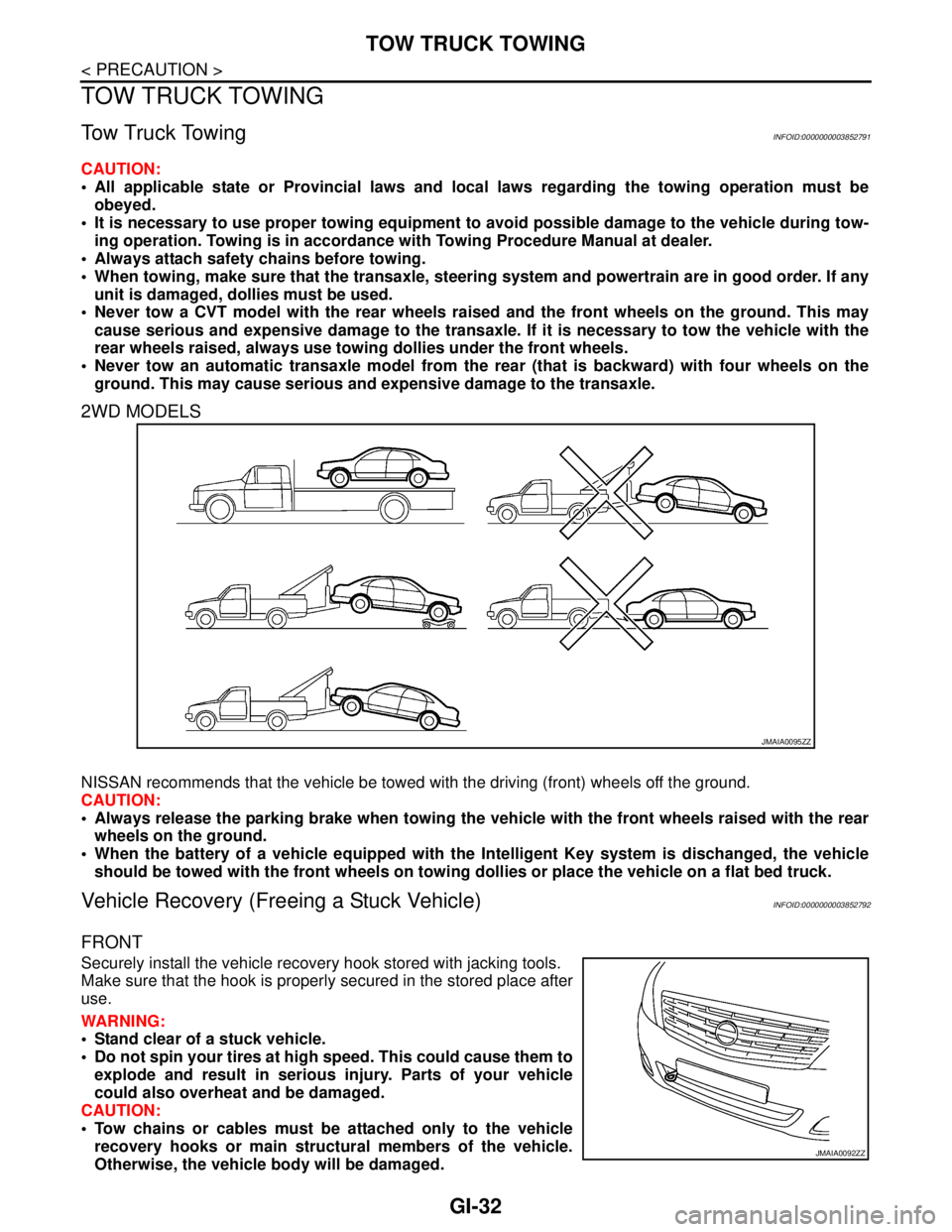
Never tow a CVT model with the rear wheels raised and the front wheels on the ground. This may
cause serious and expensive damage to the transaxle. If it is necessary to tow the vehicle with the
rear wheels raised, always use towing dollies under the front wheels.
Never tow an automatic transaxle model from the rear (that is backward) with four wheels on the
ground. This may cause serious and expensive damage to the transaxle.
2WD MODELS
NISSAN recommends that the vehicle be towed with the driving (front) wheels off the ground.
CAUTION:
Always release the parking brake when towing the vehicle with the front wheels raised with the rear
wheels on the ground.
When the battery of a vehicle equipped with the Intelligent Key system is dischanged, the vehicle
should be towed with the front wheels on towing dollies or place the vehicle on a flat bed truck.
Vehicle Recovery (Freeing a Stuck Vehicle)INFOID:0000000003852792
FRONT
Securely install the vehicle recovery hook stored with jacking tools.
Make sure that the hook is properly secured in the stored place after
use.
WARNING:
Stand clear of a stuck vehicle.
Do not spin your tires at high speed. This could cause them to
explode and result in serious injury. Parts of your vehicle
could also overheat and be damaged.
CAUTION:
Tow chains or cables must be attached only to the vehicle
recovery hooks or main structural members of the vehicle.
Otherwise, the vehicle body will be damaged.
JMAIA0095ZZ
JMAIA0092ZZ
Page 3838 of 5121
RSU-6
< ON-VEHICLE MAINTENANCE >
WHEEL ALIGNMENT
WHEEL ALIGNMENT
InspectionINFOID:0000000003813442
DESCRIPTION
Measure wheel alignment under unladen conditions.
NOTE:
“Unladen conditions” means that fuel, engine coolant, and lubricant are full. Spare tire, jack, hand tools and
mats are in designated positions.
PRELIMINARY CHECK
Check the following:
Tires for improper air pressure and wear
Road wheels for runout: refer to WT-2, "
Inspection".
Wheel bearing axial end play: refer to RAX-3, "
Inspection".
Shock absorber operation
Each mounting point of axle and suspension for looseness and deformation
Each of lower link, upper link, rear suspension member, suspension arm and shock absorber for cracks,
deformation, and other damage
Vehicle height (posture)
CAMBER
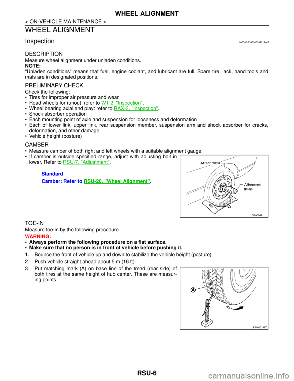
Measure camber of both right and left wheels with a suitable alignment gauge.
If camber is outside specified range, adjust with adjusting bolt in
lower. Refer to RSU-7, "
Adjustment".
TOE-IN
Measure toe-in by the following procedure.
WARNING:
Always perform the following procedure on a flat surface.
Make sure that no person is in front of vehicle before pushing it.
1. Bounce the front of vehicle up and down to stabilize the vehicle height (posture).
2. Push vehicle straight ahead about 5 m (16 ft).
3. Put matching mark (A) on base line of the tread (rear side) of
both tires at the same height of hub center. These are measur-
ing points.Standard
Camber: Refer to RSU-20, "
Wheel Alignment".
SRA096A
JPEIA0014ZZ
Page 3854 of 5121
SB-2
< PRECAUTION >
PRECAUTIONS
PRECAUTION
PRECAUTIONS
Precaution for Supplemental Restraint System (SRS) "AIR BAG" and "SEAT BELT
PRE-TENSIONER"
INFOID:0000000003949049
The Supplemental Restraint System such as “AIR BAG” and “SEAT BELT PRE-TENSIONER”, used along
with a front seat belt, helps to reduce the risk or severity of injury to the driver and front passenger for certain
types of collision. Information necessary to service the system safely is included in the “SRS AIRBAG” and
“SEAT BELT” of this Service Manual.
WARNING:
• To avoid rendering the SRS inoperative, which could increase the risk of personal injury or death in
the event of a collision which would result in air bag inflation, all maintenance must be performed by
an authorized NISSAN/INFINITI dealer.
Improper maintenance, including incorrect removal and installation of the SRS, can lead to personal
injury caused by unintentional activation of the system. For removal of Spiral Cable and Air Bag
Module, see the “SRS AIRBAG”.
Never use electrical test equipment on any circuit related to the SRS unless instructed to in this Ser-
vice Manual. SRS wiring harnesses can be identified by yellow and/or orange harnesses or harness
connectors.
Precaution for Seat Belt ServiceINFOID:0000000003848851
CAUTION:
Before removing the front seat belt pre-tensioner assembly, turn the ignition switch OFF, disconnect
both battery cables and wait at least 3 minutes.
Never use electrical test equipment for front seat belt pre-tensioner connector.
After replacing or reinstalling front seat belt pre-tensioner assembly, or reconnecting front seat belt
pre-tensioner connector, check the system function. Refer to SRC-10, "
Diagnosis Description".
Deploy front seat belt pre-tensioner assembly before disposing. Refer to SR-25, "
Caution for Air Bag
Module and Seat Belt Pre-tensioner"
Never use disassembled buckle or seat belt assembly.
Replace anchor bolts if they are deformed or worn out.
Never oil tongue and buckle.
If any component of seat belt assembly is questionable, never repair. Replace the entire seat belt
assembly.
If webbing is cut, frayed or damaged, replace seat belt assembly.
When replacing seat belt assembly, use a Genuine NISSAN seat belt assembly.
AFTER A COLLISION
WARNING:
Inspect all seat belt assemblies including retractors and attached hardware after any collision.
NISSAN recommends that all seat belt assemblies in use during a collision be replaced unless the col-
lision was minor and the belts show no damage and continue to operate properly. Not doing so could
result in serious personal injury in an accident. Seat belt assemblies not in use during a collision
should also be replaced if either damage or improper operation is noted. Seat belt pre-tensioners
should be replaced even if the seat belts are not in use during a frontal collision in which the air bags
are deployed.
Replace any seat belt assembly (including anchor bolts) if:
The seat belt is in use at the time of a collision (except for minor collisions and the belts, retractors and buck-
les show no damage and continue to operate properly).
The seat belt is damaged in an accident (i.e. torn webbing, bent retractor or guide).
The seat belt attaching point is damaged in an accident. Inspect the seat belt attaching area for damage or
distortion and repair as necessary before installing a new seat belt assembly.
Anchor bolts are deformed or worn out.
The front seat belt pre-tensioner must be replaced even if the seat belts are not in use during the collision in
which the air bags are deployed.
Page 4217 of 5121
PRECAUTIONS
SR-3
< PRECAUTION >
C
D
E
F
G
I
J
K
L
MA
B
SR
N
O
P
Diagnosis sensor unit must always be installed with their arrow marks “⇐” pointing towards the front of the
vehicle for proper operation. Also check diagnosis sensor unit for cracks, deformities or rust before installa-
tion and replace as required.
The spiral cable must be aligned in the neutral position since its rotations are limited. Do not turn steering
wheel and column after removal of steering gear.
Handle air bag module carefully. Always place driver and front passenger air bag modules with the pad side
facing upward and seat mounted front side air bag module standing with the stud bolt side facing down.
Conduct self-diagnosis to check entire SRS for proper functioning after replacing any components.
After air bag inflates, the front instrument panel assembly should be replaced if damaged.
Always replace instrument panel pad following front passenger air bag deployment.
Occupant Classification SystemINFOID:0000000003751422
Replace occupant classification system control unit and passenger front seat cushion as an assembly.
With VENTILATION SEAT: Refer to SE-89, "
Exploded View".
Without VENTILATION SEAT: Refer to SE-130, "
Exploded View".
Page 4242 of 5121
SR-28
< ON-VEHICLE REPAIR >
DISPOSAL OF AIR BAG MODULE AND SEAT BELT PRE-TENSIONER
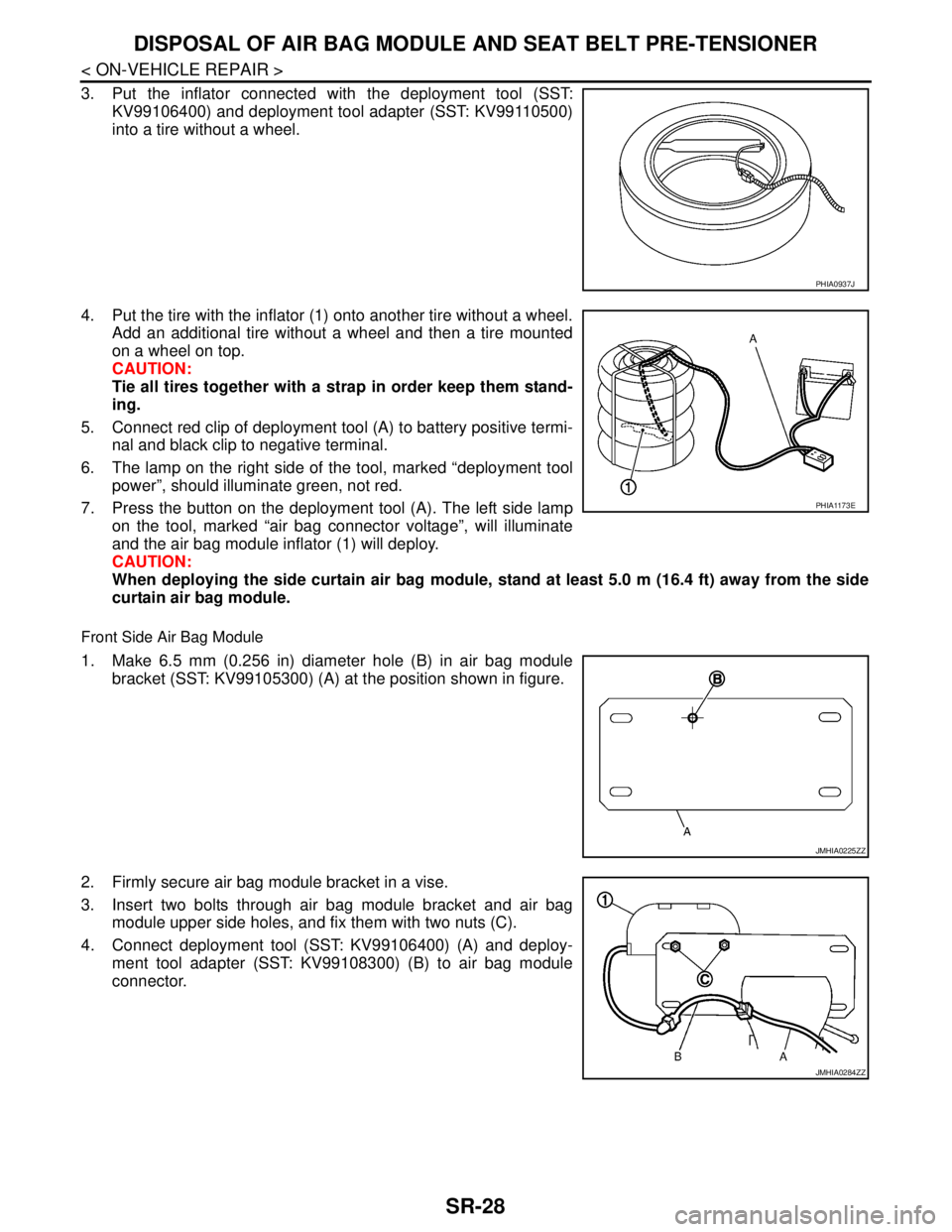
3. Put the inflator connected with the deployment tool (SST:
KV99106400) and deployment tool adapter (SST: KV99110500)
into a tire without a wheel.
4. Put the tire with the inflator (1) onto another tire without a wheel.
Add an additional tire without a wheel and then a tire mounted
on a wheel on top.
CAUTION:
Tie all tires together with a strap in order keep them stand-
ing.
5. Connect red clip of deployment tool (A) to battery positive termi-
nal and black clip to negative terminal.
6. The lamp on the right side of the tool, marked “deployment tool
power”, should illuminate green, not red.
7. Press the button on the deployment tool (A). The left side lamp
on the tool, marked “air bag connector voltage”, will illuminate
and the air bag module inflator (1) will deploy.
CAUTION:
When deploying the side curtain air bag module, stand at least 5.0 m (16.4 ft) away from the side
curtain air bag module.
Front Side Air Bag Module
1. Make 6.5 mm (0.256 in) diameter hole (B) in air bag module
bracket (SST: KV99105300) (A) at the position shown in figure.
2. Firmly secure air bag module bracket in a vise.
3. Insert two bolts through air bag module bracket and air bag
module upper side holes, and fix them with two nuts (C).
4. Connect deployment tool (SST: KV99106400) (A) and deploy-
ment tool adapter (SST: KV99108300) (B) to air bag module
connector.
PHIA0937J
PHIA1173E
JMHIA0225ZZ
JMHIA0284ZZ
Page 4390 of 5121
PRECAUTIONS
SRC-147
< PRECAUTION >
C
D
E
F
G
I
J
K
L
MA
B
SRC
N
O
P
PRECAUTION
PRECAUTIONS
Precaution for Supplemental Restraint System (SRS) "AIR BAG" and "SEAT BELT
PRE-TENSIONER"
INFOID:0000000003814141
The Supplemental Restraint System such as “AIR BAG” and “SEAT BELT PRE-TENSIONER”, used along
with a front seat belt, helps to reduce the risk or severity of injury to the driver and front passenger for certain
types of collision. Information necessary to service the system safely is included in the “SRS AIRBAG” and
“SEAT BELT” of this Service Manual.
WARNING:
To avoid rendering the SRS inoperative, which could increase the risk of personal injury or death in
the event of a collision which would result in air bag inflation, all maintenance must be performed by
an authorized NISSAN/INFINITI dealer.
Improper maintenance, including incorrect removal and installation of the SRS, can lead to personal
injury caused by unintentional activation of the system. For removal of Spiral Cable and Air Bag
Module, see the “SRS AIRBAG”.
Never use electrical test equipment on any circuit related to the SRS unless instructed to in this Ser-
vice Manual. SRS wiring harnesses can be identified by yellow and/or orange harnesses or harness
connectors.
ServiceINFOID:0000000003814109
Do not use electrical test equipment to check SRS circuits unless instructed to in this Service Manual.
Before servicing the SRS, turn ignition switch OFF, disconnect battery negative terminal and wait at least 3
minutes.
For approximately 3 minutes after the battery negative terminal is removed, it is still possible for the air bag
and seat belt pre-tensioner to deploy. Therefore, do not work on any SRS connectors or wires until at least 3
minutes have elapsed.
Diagnosis sensor unit must always be installed with their arrow marks “⇐” pointing towards the front of the
vehicle for proper operation. Also check diagnosis sensor unit for cracks, deformities or rust before installa-
tion and replace as required.
The spiral cable must be aligned in the neutral position since its rotations are limited. Do not turn steering
wheel and column after removal of steering gear.
Handle air bag module carefully. Always place driver and front passenger air bag modules with the pad side
facing upward and seat mounted front side air bag module standing with the stud bolt side facing down.
Conduct self-diagnosis to check entire SRS for proper function after replacing any components.
After air bag inflates, the front instrument panel assembly should be replaced if damaged.
Always replace instrument panel pad following front passenger air bag deployment.
Page 4399 of 5121
STEERING WHEEL
ST-9
< ON-VEHICLE MAINTENANCE >
C
D
E
F
H
I
J
K
L
MA
B
ST
N
O
P
STEERING WHEEL
InspectionINFOID:0000000003806313
STEERING WHEEL AXIAL END PLAY
1. Check installation conditions of steering gear assembly, front suspension assembly, axle and steering col-
umn assembly.
2. Check if movement exists when steering wheel is moved up and down, to the left and right and to the axial
direction.
3. Check the following items when steering wheel axial end play is out of the standard.
Check the steering column assembly mounting condition. Refer to ST-13, "
Exploded View".
Check steering gear assembly mounting condition for looseness. Refer to ST-18, "
Exploded View".
STEERING WHEEL PLAY
1. Turn steering wheel so that front wheels come to the straight-ahead position.
2. Start the engine and lightly turn steering wheel to the left and right until front wheels start to move.
3. Measure steering wheel movement on the outer circumference.
4. Check the following items when steering wheel play is out of the standard.
Check backlash for each joint of steering column assembly.
Check installation condition of steering gear assembly.
NEUTRAL POSITION STEERING WHEEL
1. Check that steering gear assembly, steering column assembly and steering wheel are installed in the cor-
rect position.
2. Perform neutral position inspection after wheel alignment. Refer to FSU-7, "
Wheel Alignment Inspection".
3. Set the vehicle to the straight-ahead position and confirm steering wheel is in the neutral position.
4. Loosen outer socket lock nut and turn inner socket to left and right equally to make fine adjustments if
steering wheel is not in the neutral position.
STEERING WHEEL TURNING FORCE
1. Park the vehicle on a level and dry surface, set parking brake.
2. Tires need to be inflated normal pressure. Refer to WT-5, "
Tire Air Pressure".
3. Start the engine.
4. Bring power steering fluid up to adequate operating temperature.Standard
Steering wheel axial end
play: Refer to ST-37, "
Steering
Wheel Axial End Play and
Play".
Standard
Steering wheel play : Refer to ST-37, "
Steering
Wheel Axial End Play and
Play".
Fluid temperature : 50 – 80°C (122 – 176°F)
Page 5009 of 5121
WT-2
< ON-VEHICLE MAINTENANCE >
ROAD WHEEL
ON-VEHICLE MAINTENANCE
ROAD WHEEL
InspectionINFOID:0000000003812916
ALUMINUM WHEEL
1. Check tires for wear and improper inflation.
2. Check wheels for deformation, cracks and other damage. If deformed, remove wheel and check wheel
runout.
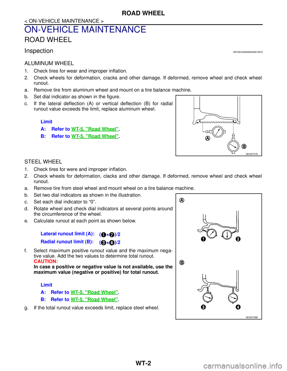
a. Remove tire from aluminum wheel and mount on a tire balance machine.
b. Set dial indicator as shown in the figure.
c. If the lateral deflection (A) or vertical deflection (B) for radial
runout value exceeds the limit, replace aluminum wheel.
STEEL WHEEL
1. Check tires for were and improper inflation.
2. Check wheels for deformation, clacks and other damage. If deformed, remove wheel and check wheel
runout.
a. Remove tire from steel wheel and mount wheel on a tire balance machine.
b. Set two dial indicators as shown in the illustration.
c. Set each dial indicator to “0”.
d. Rotate wheel and check dial indicators at several points around
the circumference of the wheel.
e. Calculate runout at each point as shown below.
f. Select maximum positive runout value and the maximum nega-
tive value. Add the two values to determine total runout.
CAUTION:
In case a positive or negative value is not available, use the
maximum value (negative or positive) for total runout.
g. If the total runout value exceeds limit, replace steel wheel.Limit
A: Refer to WT-5, "
Road Wheel".
B: Refer to WT-5, "
Road Wheel".
SEIA0737E
Lateral runout limit (A):
(+)/2
Radial runout limit (B):
(+)/2
Limit
A: Refer to WT-5, "
Road Wheel".
B: Refer to WT-5, "
Road Wheel".
SEIA0738E