stop NISSAN TEANA 2014 Workshop Manual
[x] Cancel search | Manufacturer: NISSAN, Model Year: 2014, Model line: TEANA, Model: NISSAN TEANA 2014Pages: 4801, PDF Size: 51.2 MB
Page 225 of 4801
C1116 STOP LAMP SWITCHBRC-79
< DTC/CIRCUIT DIAGNOSIS > [VDC/TCS/ABS]
C
D E
G H
I
J
K L
M A
B
BRC
N
O P
Is the inspection result normal?
YES >> GO TO 4.
NO >> Repair or replace as necessary.
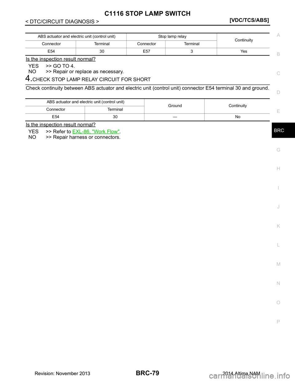
4.CHECK STOP LAMP RELAY CIRCUIT FOR SHORT
Check continuity between ABS actuator and electric unit (control unit) connector E54 terminal 30 and ground.
Is the inspection result normal?
YES >> Refer to EXL-86, "Work Flow".
NO >> Repair harness or connectors.
ABS actuator and electric unit (control unit) Stop lamp relay
Continuity
Connector Terminal Connector Terminal
E54 30 E57 3 Yes
ABS actuator and electric unit (control unit)
Ground Continuity
Connector Terminal
E54 30 — No
Revision: November 20132014 Altima NAMRevision: November 20132014 Altima NAM
Page 230 of 4801
BRC-84
< DTC/CIRCUIT DIAGNOSIS >[VDC/TCS/ABS]
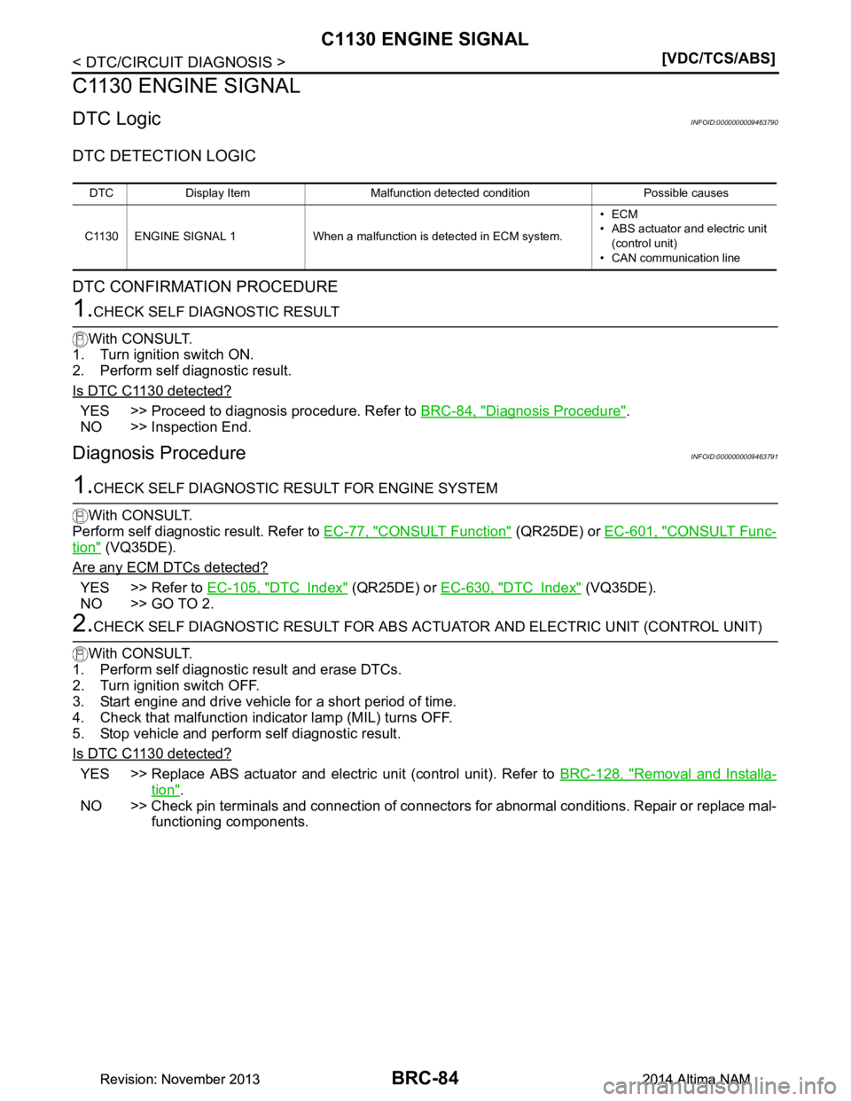
C1130 ENGINE SIGNAL
C1130 ENGINE SIGNAL
DTC LogicINFOID:0000000009463790
DTC DETECTION LOGIC
DTC CONFIRMATION PROCEDURE
1.CHECK SELF DIAGNOSTIC RESULT
With CONSULT.
1. Turn ignition switch ON.
2. Perform self diagnostic result.
Is DTC C1130 detected?
YES >> Proceed to diagnosis procedure. Refer to BRC-84, "Diagnosis Procedure".
NO >> Inspection End.
Diagnosis ProcedureINFOID:0000000009463791
1.CHECK SELF DIAGNOSTIC RESULT FOR ENGINE SYSTEM
With CONSULT.
Perform self diagnostic result. Refer to EC-77, "CONSULT Function"
(QR25DE) or EC-601, "CONSULT Func-
tion" (VQ35DE).
Are any ECM DTCs detected?
YES >> Refer to EC-105, "DTC Index" (QR25DE) or EC-630, "DTC Index" (VQ35DE).
NO >> GO TO 2.
2.CHECK SELF DIAGNOSTIC RESU LT FOR ABS ACTUATOR AND ELECTRIC UNIT (CONTROL UNIT)
With CONSULT.
1. Perform self diagnostic result and erase DTCs.
2. Turn ignition switch OFF.
3. Start engine and drive vehicle for a short period of time.
4. Check that malfunction indicator lamp (MIL) turns OFF.
5. Stop vehicle and perform self diagnostic result.
Is DTC C1130 detected?
YES >> Replace ABS actuator and electr ic unit (control unit). Refer to BRC-128, "Removal and Installa-
tion".
NO >> Check pin terminals and connection of connectors for abnormal conditions. Repair or replace mal- functioning components.
DTC Display Item Malfunction detected condition Possible causes
C1130 ENGINE SIGNAL 1 When a malfunction is detected in ECM system. •ECM
• ABS actuator and electric unit
(control unit)
• CAN communication line
Revision: November 20132014 Altima NAMRevision: November 20132014 Altima NAM
Page 233 of 4801

C1142 PRESS SENSORBRC-87
< DTC/CIRCUIT DIAGNOSIS > [VDC/TCS/ABS]
C
D E
G H
I
J
K L
M A
B
BRC
N
O P
C1142 PRESS SENSOR
DTC LogicINFOID:0000000009463794
DTC DETECTION LOGIC
DTC CONFIRMATION PROCEDURE
1.CHECK SELF DIAGNOSTIC RESULT
With CONSULT.
1. Turn ignition switch ON.
2. Perform self diagnostic result.
Is DTC C1142 detected?
YES >> Proceed to diagnosis procedure. Refer to BRC-87, "Diagnosis Procedure".
NO >> Inspection End.
Diagnosis ProcedureINFOID:0000000009463795
1.CHECK STOP LAMP SWITCH SYSTEM
Check stop lamp switch system. Refer to BRC-78, "Diagnosis Procedure"
.
Is the inspection result normal?
YES >> GO TO 2.
NO >> Repair or replace malfunctioning components.
2.CHECK BRAKE FLUID LEAKAGE
Check brake fluid leakage. Refer to BR-8, "Inspection"
.
Is the inspection result normal?
YES >> GO TO 3.
NO >> Repair or replace malfunctioning components.
3.CHECK BRAKE PEDAL
Check brake pedal. Refer to BR-13, "Inspection and Adjustment"
.
Is the inspection result normal?
YES >> GO TO 4.
NO >> Repair or replace malfunctioning components.
4.CHECK SELF DIAGNOSTIC RESULT
With CONSULT.
1. Turn ignition switch ON.
2. Perform self diagnostic result.
3. Erase DTCs.
4. Start engine and drive vehicle for a short period of time.
5. Turn ignition switch ON.
6. Perform self diagnostic result.
Is DTC C1142 detected?
YES >> Replace ABS actuator and electric unit (control unit). Refer to BRC-128, "Removal and Installa-
tion".
NO >> Inspection End.
DTC Display Item Malfunction detected condition Possible causes
C1142 PRESS SEN CIRCUIT When a malfunction is detected in master cylinder
pressure sensor. • Stop lamp switch system
• ABS actuator and electric unit
(control unit)
• Brake system
Revision: November 20132014 Altima NAMRevision: November 20132014 Altima NAM
Page 262 of 4801

BRC-116
< SYMPTOM DIAGNOSIS >[VDC/TCS/ABS]
VDC/TCS/ABS
SYMPTOM DIAGNOSIS
VDC/TCS/ABS
Symptom TableINFOID:0000000009463838
If ABS warning lamp and SLIP indicator
lamp turn ON, perform self-diagnosis.
NOTE:
• 1: The ABS does not operate when the speed is 10 km/h (6 MPH) or less.
• 2: Under the following conditions, ABS is activated and vibration is felt when brake pedal is lightly depressed (just place a foot on it).
However, this is normal.
- When shifting gears
- When driving on slippery road
- During cornering at high speed
- When passing over bumps or grooves [approximately 50 mm (1.97 in) or more]
- When pulling away just after starting engine [at approximately 10 km/h (6 MPH) or higher] Symptom Check item Reference
Excessive ABS function operation fre-
quency Brake force distribution
BRC-117, "Diagno-
sis Procedure"Looseness of front and rear axle
Wheel sensor and rotor system
Unexpected pedal reaction Brake pedal stroke
BRC-118, "Diagno-
sis Procedure"Make sure the braking force is sufficient when the ABS is not operating.
The braking distance is long Check stopping distance when the ABS is not operating. BRC-119, "Diagno-
sis Procedure"
ABS function does not operate (Note 1) ABS ac
tuator and electric unit (control unit) BRC-120, "Diag-nosis Procedure"
Pedal vibration or ABS operation sound
occurs (Note 2) Brake pedal
BRC-121, "Diag-
nosis Procedure"ABS actuator and electric unit (control unit)
Vehicle jerks duri ng VDC/TCS/ABS con-
trol ABS actuator and electric unit (control unit)
BRC-122, "Diag-
nosis Procedure"TCM
ECM
Revision: November 20132014 Altima NAMRevision: November 20132014 Altima NAM
Page 265 of 4801
THE BRAKING DISTANCE IS LONGBRC-119
< SYMPTOM DIAGNOSIS > [VDC/TCS/ABS]
C
D E
G H
I
J
K L
M A
B
BRC
N
O P
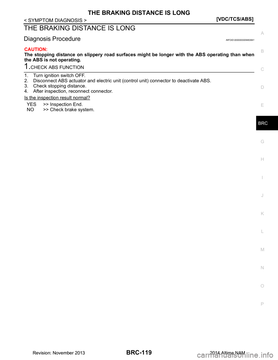
THE BRAKING DISTANCE IS LONG
Diagnosis ProcedureINFOID:0000000009463841
CAUTION:
The stopping distance on slippery road surfaces might be longer with the ABS operating than when
the ABS is not operating.
1.CHECK ABS FUNCTION
1. Turn ignition switch OFF.
2. Disconnect ABS actuator and el ectric unit (control unit) connector to deactivate ABS.
3. Check stopping distance.
4. After inspection, reconnect connector.
Is the inspection result normal?
YES >> Inspection End.
NO >> Check brake system.
Revision: November 20132014 Altima NAMRevision: November 20132014 Altima NAM
Page 269 of 4801

NORMAL OPERATING CONDITIONBRC-123
< SYMPTOM DIAGNOSIS > [VDC/TCS/ABS]
C
D E
G H
I
J
K L
M A
B
BRC
N
O P
NORMAL OPERATING CONDITION
DescriptionINFOID:0000000009463845
Symptom Result
Slight vibrations are felt on the brake pedal and operation noises occur when VDC, TCS or ABS is activated. This is a normal condi-
tion due to the VDC,
TCS or ABS activation.
Stopping distance is longer than that of vehicles without ABS when the vehicle drives on rough, gravel, or
snow-covered (fresh, deep snow) roads.
The brake pedal moves and generates noises when TCS or VDC is activated due to rapid acceleration or
sharp turn.
The brake pedal vibrates and motor operation noises occur from the engine room after the engine starts and
just after the vehicle starts. This is normal, and it is
caused by the ABS op-
eration check.
Depending on the road conditions, the driver may experience a sluggish feel in the brake pedal. This is normal, because TCS places the highest
priority on the optimum
traction (stability).
TCS may activate momentarily if wheel speed changes when driving where road friction coefficient varies,
when downshifting, or when fully depressing accelerator pedal.
The ABS warning lamp and SLIP indicator lamp may turn ON when the vehicle is subject to strong shaking
or large vibration, such as when the vehicle is rotating on a turntable or located on a ship while the engine
is running. In this case, restart the
engine on a normal
road. If the normal con-
dition is restored, there
is no malfunction. At
that time, erase the self-
diagnosis memory.
VDC may not operate normally or th
e ABS warning lamp, and SLIP indicato r lamp may illuminate when driv-
ing on a road that is extremely slanted (e.g., bank in a circuit course).
A malfunction may occur in the yaw rate/side/decel G sensor system when the vehicle turns sharply, such
as during a spin turn, axle turn, or drift driving, while the VDC function is OFF (VDC OFF indicator lamp illu-
minated).
The vehicle speed will not increase even though the accelerator pedal is depressed, when inspecting the
speedometer on a 2-wheel chassis dynamometer. Normal (Deactivate the
VDC/TCS function be-
fore performing an in-
spection on a chassis
dynamometer.)
SLIP indicator lamp may simultaneously turn ON when low tire pressure warning lamp turns ON. This is not a VDC sys-
tem error but results
from characteristic
change of tire.
Revision: November 20132014 Altima NAMRevision: November 20132014 Altima NAM
Page 364 of 4801
CHG
DIAGNOSIS AND REPAIR WORKFLOWCHG-19
< BASIC INSPECTION >
C
D E
F
G H
I
J
K L
B
A
O P
N
>> GO TO 2.
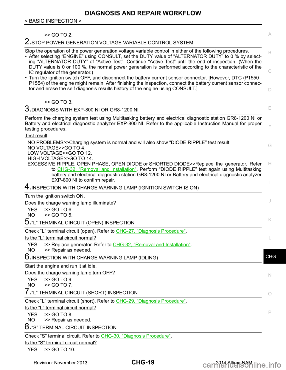
2.STOP POWER GENERATION VOLT
AGE VARIABLE CONTROL SYSTEM
Stop the operation of the power generation voltage variabl e control in either of the following procedures.
• After selecting “ENGINE” using CONSULT, set the DUTY value of “ALTERNATOR DUTY” to 0 % by select- ing “ALTERNATOR DUTY” of “Active Test”. Continue “Active Test” until the end of inspection. (When the
DUTY value is 0 or 100 %, the normal power generation is performed according to the characteristic of the
IC regulator of the generator.)
• Turn the ignition switch OFF, and disconnect the batte ry current sensor connector. [However, DTC (P1550–
P1554) of the engine might remain. After finishing the inspection, connect the battery current sensor connec-
tor and erase the self diagnosis results history of the engine using CONSULT.]
>> GO TO 3.
3.DIAGNOSIS WITH EXP-800 NI OR GR8-1200 NI
Perform the charging system test using Multitasking battery and electrical diagnostic station GR8-1200 NI or
Battery and electrical diagnostic analyzer EXP-800 NI. Re fer to the applicable Instruction Manual for proper
testing procedures.
Test result
NO PROBLEMS>>Charging system is normal and will also show “DIODE RIPPLE” test result.
NO VOLTAGE>>GO TO 4.
LOW VOLTAGE>>GO TO 12.
HIGH VOLTAGE>>GO TO 14.
EXCESSIVE RIPPLE, OPEN PHASE, OPEN DIODE or SHORTED DIODE>>Replace the generator. Refer
to CHG-32, "Removal and Installation"
. Perform “DIODE RIPPLE” test again using Multitasking
battery and electrical diagnostic station GR8-1200 NI or Battery and electrical diagnostic analyzer
EXP-800 NI to confirm repair.
4.INSPECTION WITH CHARGE WARNING LAMP (IGNITION SWITCH IS ON)
Turn the ignition switch ON.
Does the charge warning lamp illuminate?
YES >> GO TO 6.
NO >> GO TO 5.
5.“L” TERMINAL CIRCUIT (OPEN) INSPECTION
Check “L” terminal circuit (open). Refer to CHG-27, "Diagnosis Procedure"
.
Is the
“L” terminal circuit normal?
YES >> Replace generator. Refer to CHG-32, "Removal and Installation".
NO >> Repair as needed.
6.INSPECTION WITH CHARGE WARNING LAMP (IDLING)
Start the engine and run it at idle.
Does the charge warning lamp turn OFF?
YES >> GO TO 9.
NO >> GO TO 7.
7.“L” TERMINAL CIRCUIT (SHORT) INSPECTION
Check “L” terminal circuit (short). Refer to CHG-29, "Diagnosis Procedure"
.
Is the
“L” terminal circuit normal?
YES >> GO TO 8.
NO >> Repair as needed.
8.“S” TERMINAL CIRCUIT INSPECTION
Check “S” terminal circuit. Refer to CHG-30, "Diagnosis Procedure"
.
Is the
“S” terminal circuit normal?
YES >> GO TO 10.
Revision: November 20132014 Altima NAMRevision: November 20132014 Altima NAM
Page 366 of 4801

CHG
DIAGNOSIS AND REPAIR WORKFLOWCHG-21
< BASIC INSPECTION >
C
D E
F
G H
I
J
K L
B
A
O P
N
• Use fully charged battery.
DETAILED FLOW
1.PRELIMINARY INSPECTION
Perform the preliminary inspection. Refer to CHG-23, "Diagnosis Procedure"
.
>> GO TO 2.
2.STOP POWER GENERATION VOLT AGE VARIABLE CONTROL SYSTEM
Stop the operation of the power generation voltage variabl e control in either of the following procedures:
• After selecting “ENGINE” using CONSULT, set the DUTY value of “ALTERNATOR DUTY” to 0 % by select- ing “ALTERNATOR DUTY” with “Active Test”. Continue “Active Test” until the end of inspection. (When the
DUTY value is 0 or 100 %, the normal power generation is performed according to the characteristic of the
IC regulator of the generator.)
• Turn the ignition switch OFF, and disconnect the batte ry current sensor connector. [However, DTC (P1550 -
P1554) of the engine might remain. After finishing the inspection, connect the battery current sensor connec-
tor and erase the self-diagnostic results history of the engine using CONSULT.]
>> GO TO 3.
3.INSPECTION WITH CHARGE WARNING LA MP (IGNITION SWITCH IS TURNED ON)
When ignition switch is turned ON.
Does the charge warning lamp illuminate?
ALMIA0577GB
Revision: November 20132014 Altima NAMRevision: November 20132014 Altima NAM
Page 392 of 4801
CO-12
< PERIODIC MAINTENANCE >[QR25DE]
ENGINE COOLANT
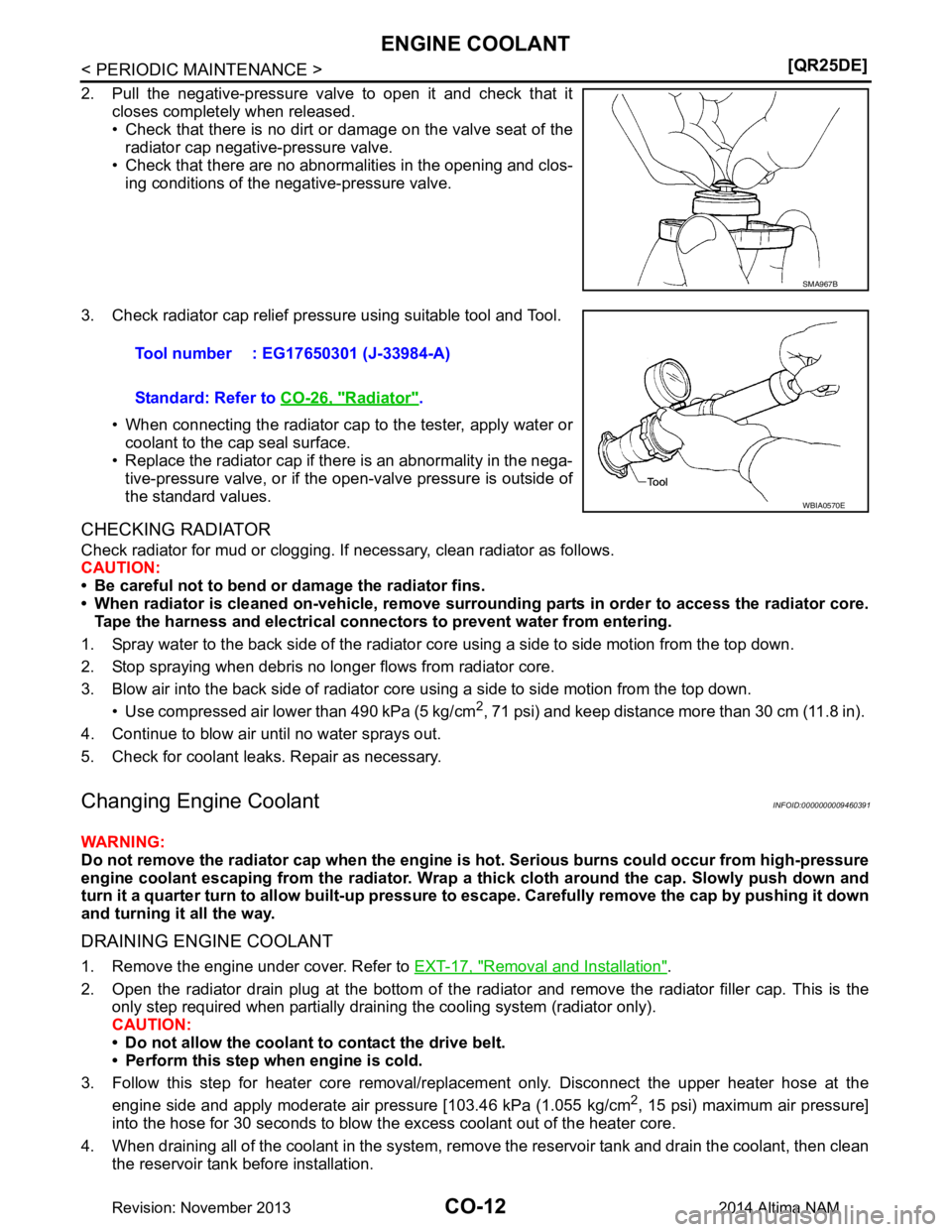
2. Pull the negative-pressure valve to open it and check that it
closes completely when released.
• Check that there is no dirt or damage on the valve seat of the
radiator cap negative-pressure valve.
• Check that there are no abnormalities in the opening and clos- ing conditions of the negative-pressure valve.
3. Check radiator cap relief pressure using suitable tool and Tool. • When connecting the radiator cap to the tester, apply water orcoolant to the cap seal surface.
• Replace the radiator cap if there is an abnormality in the nega-
tive-pressure valve, or if the open-valve pressure is outside of
the standard values.
CHECKING RADIATOR
Check radiator for mud or clogging. If necessary, clean radiator as follows.
CAUTION:
• Be careful not to bend or damage the radiator fins.
• When radiator is cleaned on-vehicle, remove surr ounding parts in order to access the radiator core.
Tape the harness and electrical connectors to prevent water from entering.
1. Spray water to the back side of the radiator co re using a side to side motion from the top down.
2. Stop spraying when debris no longer flows from radiator core.
3. Blow air into the back side of radiator core using a side to side motion from the top down.
• Use compressed air lower than 490 kPa (5 kg/cm
2, 71 psi) and keep distance more than 30 cm (11.8 in).
4. Continue to blow air until no water sprays out.
5. Check for coolant leaks. Repair as necessary.
Changing Engine CoolantINFOID:0000000009460391
WARNING:
Do not remove the radiator cap when the engine is hot. Serious burns could occur from high-pressure
engine coolant escaping from the radiator. Wrap a th ick cloth around the cap. Slowly push down and
turn it a quarter turn to allow built-up pressure to escape. Carefully remove the cap by pushing it down
and turning it all the way.
DRAINING ENGINE COOLANT
1. Remove the engine under cover. Refer to EXT-17, "Removal and Installation".
2. Open the radiator drain plug at the bottom of the radi ator and remove the radiator filler cap. This is the
only step required when partially draining the cooling system (radiator only).
CAUTION:
• Do not allow the coolant to contact the drive belt.
• Perform this step when engine is cold.
3. Follow this step for heater core removal/replac ement only. Disconnect the upper heater hose at the
engine side and apply moderate air pressure [103.46 kPa (1.055 kg/cm
2, 15 psi) maximum air pressure]
into the hose for 30 seconds to blow t he excess coolant out of the heater core.
4. When draining all of the coolant in the system, re move the reservoir tank and drain the coolant, then clean
the reservoir tank before installation.
SMA967B
Tool number : EG17650301 (J-33984-A)
Standard: Refer to CO-26, "Radiator"
.
WBIA0570E
Revision: November 20132014 Altima NAM
Page 395 of 4801
ENGINE COOLANTCO-15
< PERIODIC MAINTENANCE > [QR25DE]
C
D E
F
G H
I
J
K L
M A
CO
NP
O
1. Fill the radiator from the filler neck above the r
adiator upper hose and reservoir tank with clean water and
reinstall the radiator filler cap.
2. Run the engine until it reaches normal operating temperature.
3. Rev the engine two or three times under no-load.
4. Stop the engine and wait until it cools down.
5. Drain the water from the system. Refer to CO-12, "Changing Engine Coolant"
.
6. Repeat steps 1 through 5 until clear water begins to drain from the radiator.
Revision: November 20132014 Altima NAM