wiring diagram NISSAN TEANA 2014 Workshop Manual
[x] Cancel search | Manufacturer: NISSAN, Model Year: 2014, Model line: TEANA, Model: NISSAN TEANA 2014Pages: 4801, PDF Size: 51.2 MB
Page 254 of 4801
![NISSAN TEANA 2014 Workshop Manual
BRC-108
< DTC/CIRCUIT DIAGNOSIS >[VDC/TCS/ABS]
PARKING BRAKE SWITCH
PARKING BRAKE SWITCH
Component Function CheckINFOID:0000000009463823
1.CHECK PARKING BRAKE SWITCH OPERATION
Check that brake warnin](/img/5/57390/w960_57390-253.png "NISSAN TEANA 2014 Workshop Manual
BRC-108
< DTC/CIRCUIT DIAGNOSIS >[VDC/TCS/ABS]
PARKING BRAKE SWITCH
PARKING BRAKE SWITCH
Component Function CheckINFOID:0000000009463823
1.CHECK PARKING BRAKE SWITCH OPERATION
Check that brake warnin")
BRC-108
< DTC/CIRCUIT DIAGNOSIS >[VDC/TCS/ABS]
PARKING BRAKE SWITCH
PARKING BRAKE SWITCH
Component Function CheckINFOID:0000000009463823
1.CHECK PARKING BRAKE SWITCH OPERATION
Check that brake warning lamp in combination me ter turns ON/OFF when parking brake is actuated.
Is the inspection result normal?
YES >> Inspection End.
NO >> Proceed to diagnosis procedure. Refer to BRC-108, "Diagnosis Procedure"
.
Diagnosis ProcedureINFOID:0000000009463824
Regarding Wiring Diagram information, refer to BRC-47, "Wiring Diagram".
1.CONNECTOR INSPECTION
1. Turn ignition switch OFF.
2. Disconnect combination meter and parking brake switch connectors.
3. Check connectors and terminals for deformation, disconnection, looseness or damage.
Is the inspection result normal?
YES >> GO TO 2.
NO >> Repair or replace as necessary.
2.CHECK PARKING BRAKE SWITCH
Check parking brake switch. Refer to BRC-109, "Component Inspection"
.
Is the inspection result normal?
YES >> GO TO 3.
NO >> Replace parking brake switch. Refer to PB-7, "Exploded View"
.
3.CHECK PARKING BRAKE SWITCH SIGNAL
With CONSULT.
1. Connect combination meter connector and parking brake switch connectors.
2. Turn ignition switch ON.
3. In “DATA MONITOR” select “PARK BRAKE SW” and check parking brake switch signal.
Is the inspection result normal?
YES >> Refer to BRC-55, "Work Flow".
NO >> GO TO 4.
4.CHECK PARKING BRAKE SWITCH CIRCUIT
1. Turn ignition switch OFF.
2. Disconnect combination meter and parking brake switch connectors.
3. Check continuity between combination meter connec tor M24 terminal 12 and parking brake switch con-
nector E35 terminal 1.
4. Check continuity between combination meter connector and ground.
Condition DATA MONITOR
Actuate parking brake On
Release parking brake Off
Combination meter Parking brake switch Continuity
Connector Terminal Connector Terminal
M24 12 E35 1 Yes
Revision: November 20132014 Altima NAMRevision: November 20132014 Altima NAM
Page 256 of 4801
![NISSAN TEANA 2014 Workshop Manual
B RC-110
< DTC/CIRCUIT DIAGNOSIS >[VDC/TCS/ABS]
VDC OFF SWITCH
VDC OFF SWITCH
Component Function CheckINFOID:0000000009463826
1.CHECK VDC OFF SWITCH OPERATION
Check that VDC OFF indicator lamp in com](/img/5/57390/w960_57390-255.png "NISSAN TEANA 2014 Workshop Manual
B RC-110
< DTC/CIRCUIT DIAGNOSIS >[VDC/TCS/ABS]
VDC OFF SWITCH
VDC OFF SWITCH
Component Function CheckINFOID:0000000009463826
1.CHECK VDC OFF SWITCH OPERATION
Check that VDC OFF indicator lamp in com")
B RC-110
< DTC/CIRCUIT DIAGNOSIS >[VDC/TCS/ABS]
VDC OFF SWITCH
VDC OFF SWITCH
Component Function CheckINFOID:0000000009463826
1.CHECK VDC OFF SWITCH OPERATION
Check that VDC OFF indicator lamp in combination meter turns ON/OFF when VDC OFF switch is operated.
Is the inspection result normal?
YES >> Inspection End.
NO >> Proceed to diagnosis procedure. Refer to BRC-110, "Diagnosis Procedure"
.
Diagnosis ProcedureINFOID:0000000009463827
Regarding Wiring Diagram information, refer to BRC-47, "Wiring Diagram".
1.CONNECTOR INSPECTION
1. Turn ignition switch OFF.
2. Disconnect ABS actuator and electric unit (c ontrol unit) and VDC OFF switch connectors.
3. Check connectors and terminals for deformation, disconnection, looseness or damage.
Is the inspection result normal?
YES >> GO TO 2.
NO >> Repair or replace as necessary.
2.CHECK VDC OFF SWITCH
Check VDC OFF switch. Refer to BRC-111, "Component Inspection"
.
Is the inspection result normal?
YES >> GO TO 3.
NO >> Replace VDC OFF switch. Refer to BRC-130, "Removal and Installation"
.
3.CHECK VDC OFF SWITCH SIGNAL
With CONSULT.
1. Connect ABS actuator and electric unit (c ontrol unit) and VDC OFF switch connectors.
2. Turn ignition switch ON.
3. In “DATA MONITOR” select “OFF SW” and check VDC OFF switch signal.
Is the inspection result normal?
YES >> Refer to BRC-55, "Work Flow".
NO >> GO TO 4.
4.CHECK VDC OFF SWITCH CIRCUIT
1. Turn ignition switch OFF.
2. Disconnect ABS actuator and electric unit (c ontrol unit) and VDC OFF switch connectors.
3. Check continuity between ABS actuator and electr ic unit (control unit) connector E54 terminal 15 and
VDC OFF switch connector M72 terminal 1.
4. Check continuity between ABS actuator and electric unit (control unit) connector terminal E54 terminal 15
and ground.
Condition DATA MONITOR
VDC OFF switch is pressed and released On
VDC OFF switch is pressed and released again Off
ABS actuator and electric unit (control unit) VDC OFF switch
Continuity
Connector Terminal Connector Terminal
E54 15 M72 1 Yes
Revision: November 20132014 Altima NAMRevision: November 20132014 Altima NAM
Page 346 of 4801

CHG
CHG-1
ELECTRICAL & POWER CONTROL
C
D E
F
G H
I
J
K L
B
SECTION CHG
A
O P
N
CONTENTS
CHARGING SYSTEM
PRECAUTION ................
...............................3
PRECAUTIONS .............................................. .....3
Precaution for Supplemental Restraint System
(SRS) "AIR BAG" and "SEAT BELT PRE-TEN-
SIONER" ............................................................. ......
3
Precaution for Power Generation Voltage Variable
Control System .................................................... ......
3
PREPARATION ............................................4
PREPARATION .............................................. .....4
Special Service Tool ........................................... ......4
Commercial Service Tool ..........................................4
SYSTEM DESCRIPTION ..............................5
COMPONENT PARTS ................................... .....5
QR25DE ................................................................. ......5
QR25DE : Component Parts Location ......................5
QR25DE : Component Description ...........................6
VQ35DE ................................................................. ......6
VQ35DE : Component Parts Location ......................7
VQ35DE : Component Description ...........................8
CHARGING SYSTEM ..................................... .....9
System Diagram .................................................. ......9
System Description ...................................................9
Component Description ............................................9
POWER GENERATION VOLTAGE VARI-
ABLE CONTROL SYSTEM ............................ ....
10
System Diagram .................................................. ....10
System Description .................................................10
Component Description ...........................................10
WIRING DIAGRAM ......................................12
CHARGING SYSTEM ..................................... ....12
Wiring Diagram ................................................... ....12
BASIC INSPECTION ...................................17
DIAGNOSIS AND REPAIR WORKFLOW ........17
Work Flow (With EXP-800 NI or GR8-1200 NI) .......17
Work Flow (Without EXP-80 0 NI or GR8-1200 NI) ....20
DTC/CIRCUIT DIAGNOSIS .........................23
CHARGING SYSTEM PRELIMINARY IN-
SPECTION ....... ................................ .................
23
Diagnosis Procedure ........................................... ....23
POWER GENERATION VOLTAGE VARI-
ABLE CONTROL SYSTEM OPERATION IN-
SPECTION ....... ................................ .................
24
Diagnosis Procedure ........................................... ....24
B TERMINAL CIRCUIT .....................................26
Description ...............................................................26
Diagnosis Procedure ...............................................26
L TERMINAL CIRCUIT (OPEN) ........................27
Description ...............................................................27
Diagnosis Procedure ...............................................27
L TERMINAL CIRCUIT (SHORT) .....................29
Description ...............................................................29
Diagnosis Procedure ...............................................29
S TERMINAL CIRCUIT .....................................30
Description ...............................................................30
Diagnosis Procedure ...............................................30
SYMPTOM DIAGNOSIS ..............................31
CHARGING SYSTEM .......................................31
Symptom Table ................................................... ....31
REMOVAL AND INSTALLATION ...............32
GENERATOR ....................................................32
Removal and Installation ..................................... ....32
Revision: November 20132014 Altima NAMRevision: November 20132014 Altima NAM
Page 357 of 4801
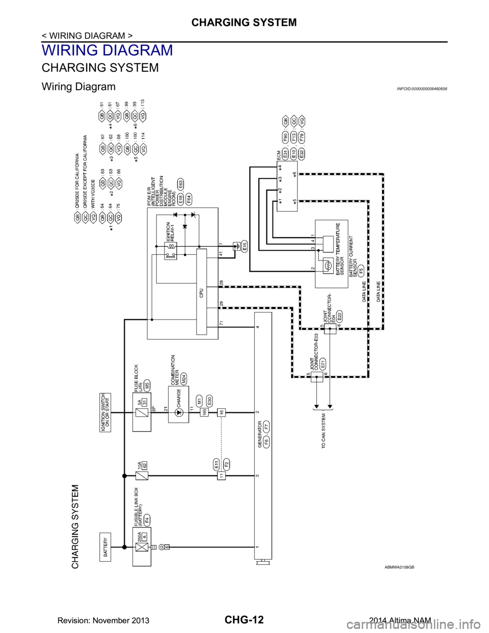
CHG-12
< WIRING DIAGRAM >
CHARGING SYSTEM
WIRING DIAGRAM
CHARGING SYSTEM
Wiring Diagram INFOID:0000000009460656
ABMWA2158GB
Revision: November 20132014 Altima NAMRevision: November 20132014 Altima NAM
Page 358 of 4801
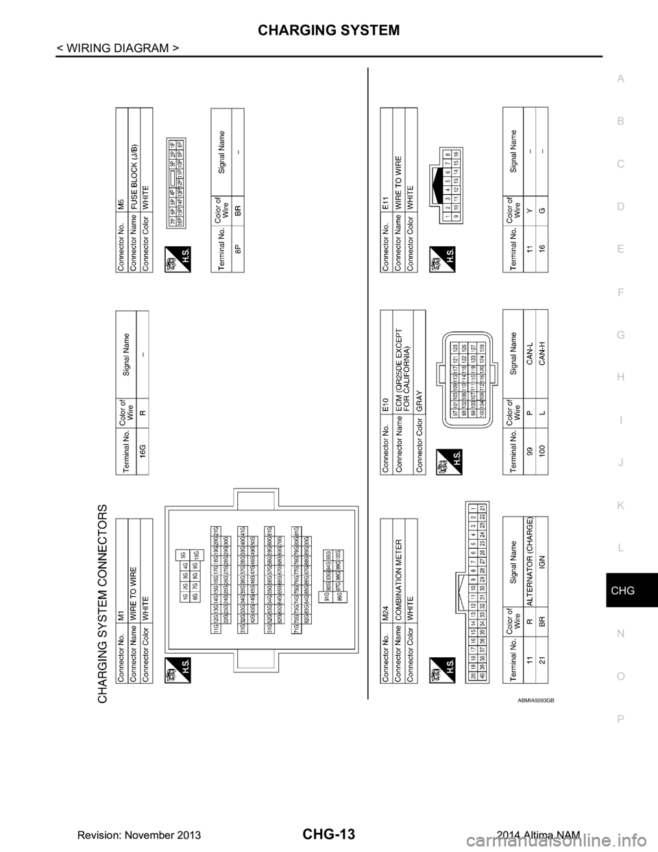
CHG
CHARGING SYSTEMCHG-13
< WIRING DIAGRAM >
C
D E
F
G H
I
J
K L
B
A
O P
N
ABMIA5093GB
Revision: November 20132014 Altima NAMRevision: November 20132014 Altima NAM
Page 359 of 4801
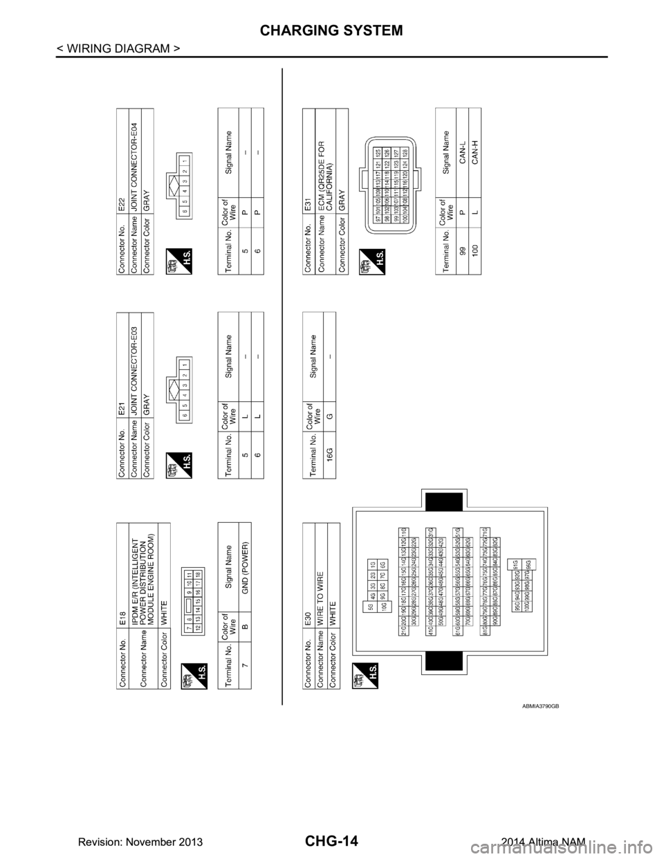
CHG-14
< WIRING DIAGRAM >
CHARGING SYSTEM
ABMIA3790GB
Revision: November 20132014 Altima NAMRevision: November 20132014 Altima NAM
Page 360 of 4801
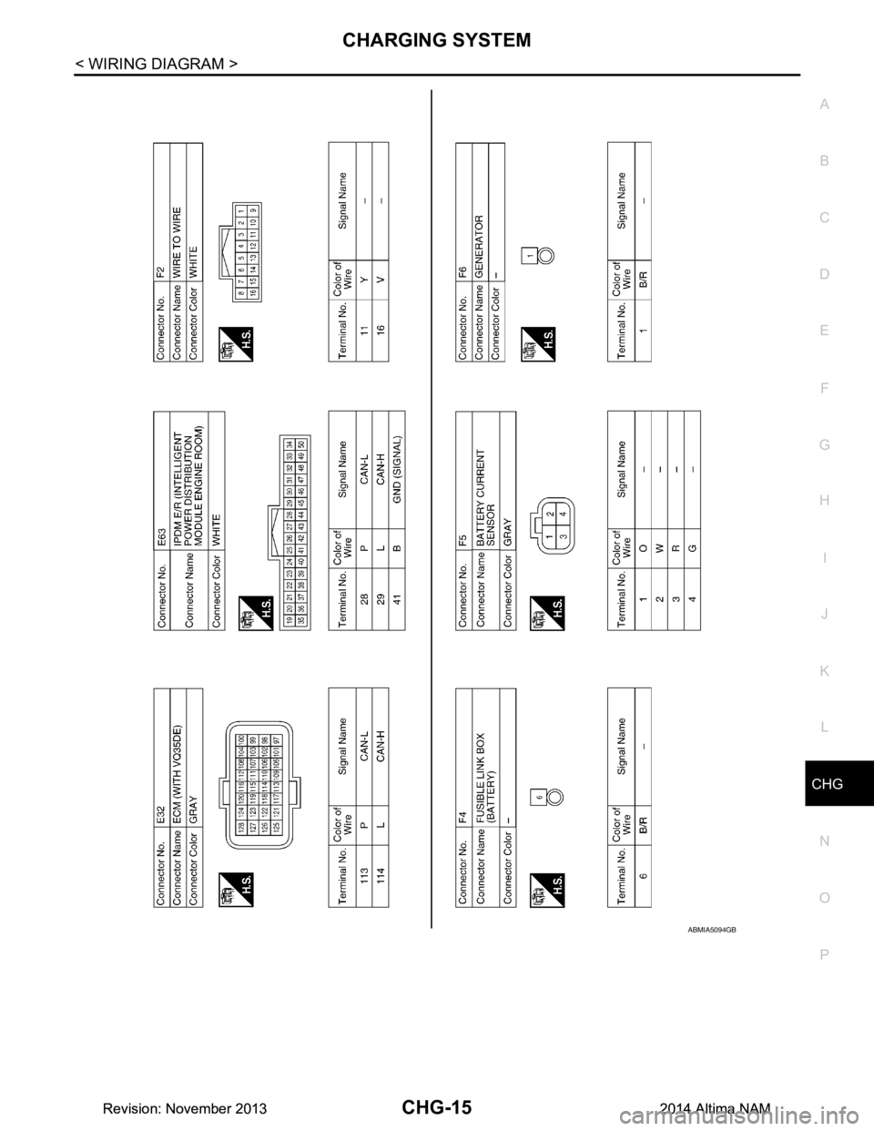
CHG
CHARGING SYSTEMCHG-15
< WIRING DIAGRAM >
C
D E
F
G H
I
J
K L
B
A
O P
N
ABMIA5094GB
Revision: November 20132014 Altima NAMRevision: November 20132014 Altima NAM
Page 361 of 4801
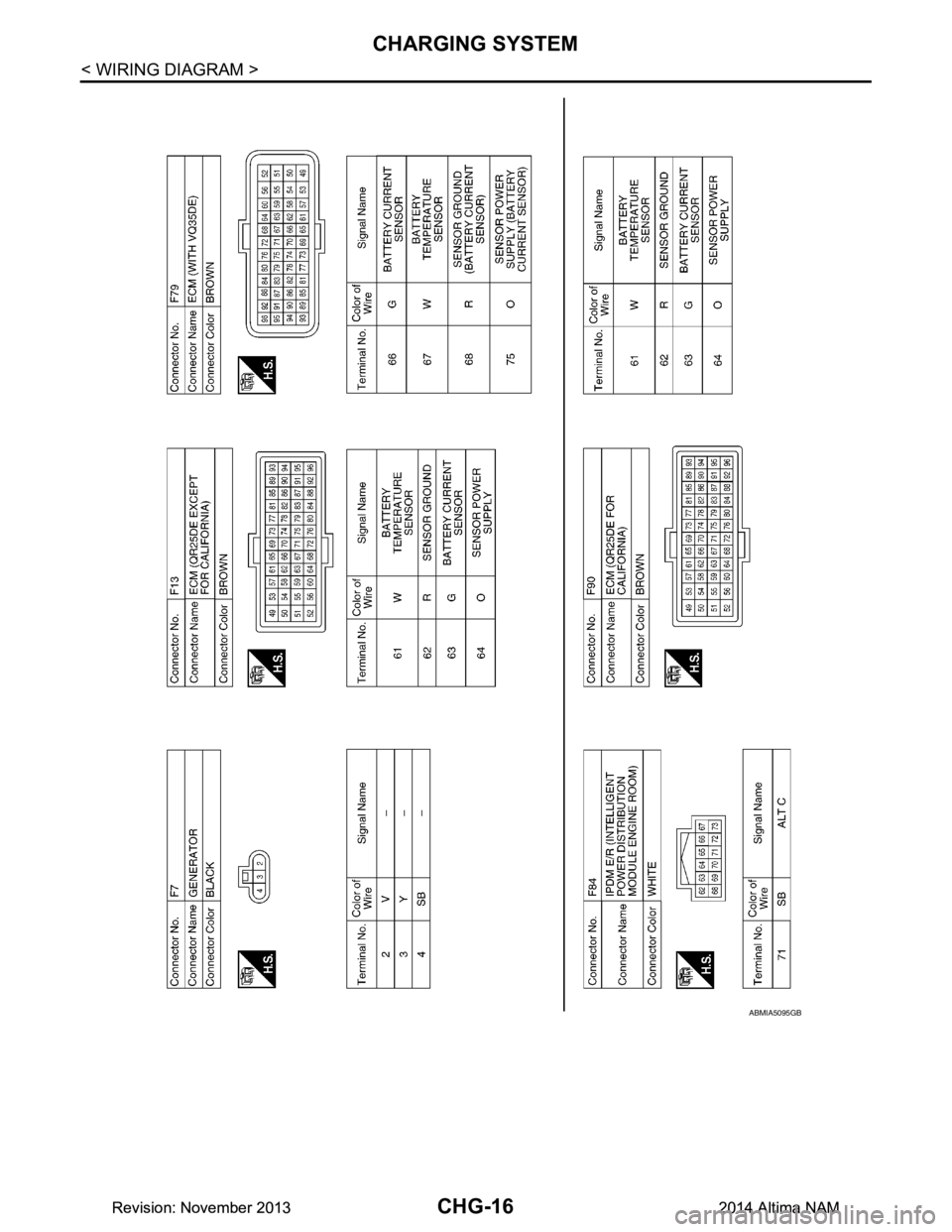
CHG-16
< WIRING DIAGRAM >
CHARGING SYSTEM
ABMIA5095GB
Revision: November 20132014 Altima NAMRevision: November 20132014 Altima NAM
Page 369 of 4801
CHG-24
< DTC/CIRCUIT DIAGNOSIS >
POWER GENERATION VOLTAGE VARIABLE CONTROL SYSTEM OPERATION
INSPECTION
POWER GENERATION VOLTAGE VA RIABLE CONTROL SYSTEM OPER-
ATION INSPECTION
Diagnosis ProcedureINFOID:0000000009460660
Regarding Wiring Diagram information. Refer to CHG-12, "Wiring Diagram".
CAUTION:
When performing this in spection, always use a charged battery that has completed the battery inspec-
tion. (When the charging rate of the battery is lo w, the response speed of the voltage change will
become slow. This can cause an incorrect inspection.)
1.CHECK ECM (CONSULT)
Perform ECM self-diagnosis with CONSULT. Refer to EC-77, "CONSULT Function"
(QR25DE) or EC-601,
"CONSULT Function" (VQ35DE).
Self
-diagnostic results content
No malfunction detected>> GO TO 2.
Malfunction detected>> Check applicable parts, and repair or replace corresponding parts.
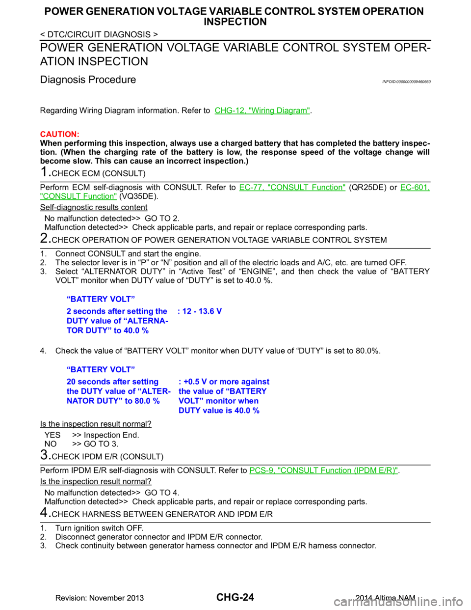
2.CHECK OPERATION OF POWER GENERATION VOLTAGE VARIABLE CONTROL SYSTEM
1. Connect CONSULT and start the engine.
2. The selector lever is in “P” or “N” position and al l of the electric loads and A/C, etc. are turned OFF.
3. Select “ALTERNATOR DUTY” in “Active Test” of “ENGINE”, and then check the value of “BATTERY
VOLT” monitor when DUTY value of “DUTY” is set to 40.0 %.
4. Check the value of “BATTERY VOLT” monitor when DUTY value of “DUTY” is set to 80.0%.
Is the inspection result normal?
YES >> Inspection End.
NO >> GO TO 3.
3.CHECK IPDM E/R (CONSULT)
Perform IPDM E/R self-diagnosis with CONSULT. Refer to PCS-9, "CONSULT Function (IPDM E/R)"
.
Is the inspection result normal?
No malfunction detected>> GO TO 4.
Malfunction detected>> Check applicable parts, and repair or replace corresponding parts.
4.CHECK HARNESS BETWEEN GE NERATOR AND IPDM E/R
1. Turn ignition switch OFF.
2. Disconnect generator connector and IPDM E/R connector.
3. Check continuity between generator harnes s connector and IPDM E/R harness connector.
“BATTERY VOLT”
2 seconds after setting the
DUTY value of “ALTERNA-
TOR DUTY” to 40.0 % : 12 - 13.6 V
“BATTERY VOLT”
20 seconds after setting
the DUTY value of “ALTER-
NATOR DUTY” to 80.0 % : +0.5 V or more against
the value of “BATTERY
VOLT” monitor when
DUTY value is 40.0 %
Revision: November 20132014 Altima NAMRevision: November 20132014 Altima NAM
Page 371 of 4801
CHG-26
< DTC/CIRCUIT DIAGNOSIS >
B TERMINAL CIRCUIT
B TERMINAL CIRCUIT
DescriptionINFOID:0000000009460661
“B” terminal circuit supplies power to charge the battery and to operate the vehicles electrical system.
Diagnosis ProcedureINFOID:0000000009460662
Regarding Wiring Diagram information. Refer to CHG-12, "Wiring Diagram".
1.CHECK “B” TERMINAL CONNECTION
1. Turn ignition switch OFF.
2. Check if “B” terminal is clean and tight.
Is the inspection result normal?
YES >> GO TO 2.
NO >> Repair terminal “B” connection. Confirm repa ir by performing complete Charging system test
using the EXP-800 NI or GR8-1200 NI (if availabl e). Refer to applicable Instruction Manual for
proper testing procedures.
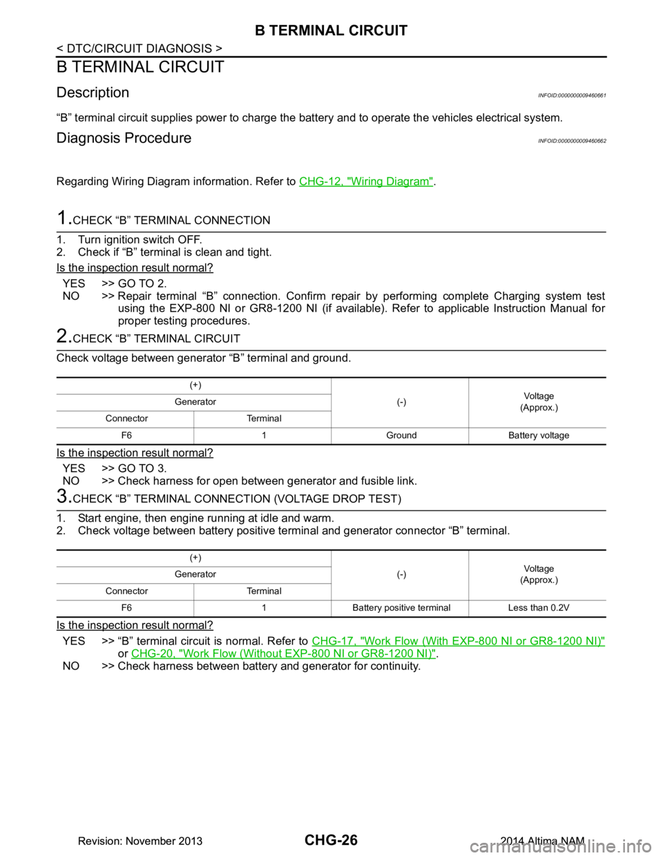
2.CHECK “B” TERMINAL CIRCUIT
Check voltage between generator “B” terminal and ground.
Is the inspection result normal?
YES >> GO TO 3.
NO >> Check harness for open between generator and fusible link.
3.CHECK “B” TERMINAL CONNECT ION (VOLTAGE DROP TEST)
1. Start engine, then engine running at idle and warm.
2. Check voltage between battery positive te rminal and generator connector “B” terminal.
Is the inspection result normal?
YES >> “B” terminal circuit is normal. Refer to CHG-17, "Work Flow (With EXP-800 NI or GR8-1200 NI)"
or CHG-20, "Work Flow (Without EXP-800 NI or GR8-1200 NI)".
NO >> Check harness between battery and generator for continuity.
(+)
(-)Voltage
(Approx.)
Generator
Connector Terminal F6 1 Ground Battery voltage
(+) (-)Voltage
(Approx.)
Generator
Connector Terminal F6 1 Battery positive terminal Less than 0.2V
Revision: November 20132014 Altima NAMRevision: November 20132014 Altima NAM