boot NISSAN TERRANO 2002 Service Repair Manual
[x] Cancel search | Manufacturer: NISSAN, Model Year: 2002, Model line: TERRANO, Model: NISSAN TERRANO 2002Pages: 1767, PDF Size: 41.51 MB
Page 230 of 1767
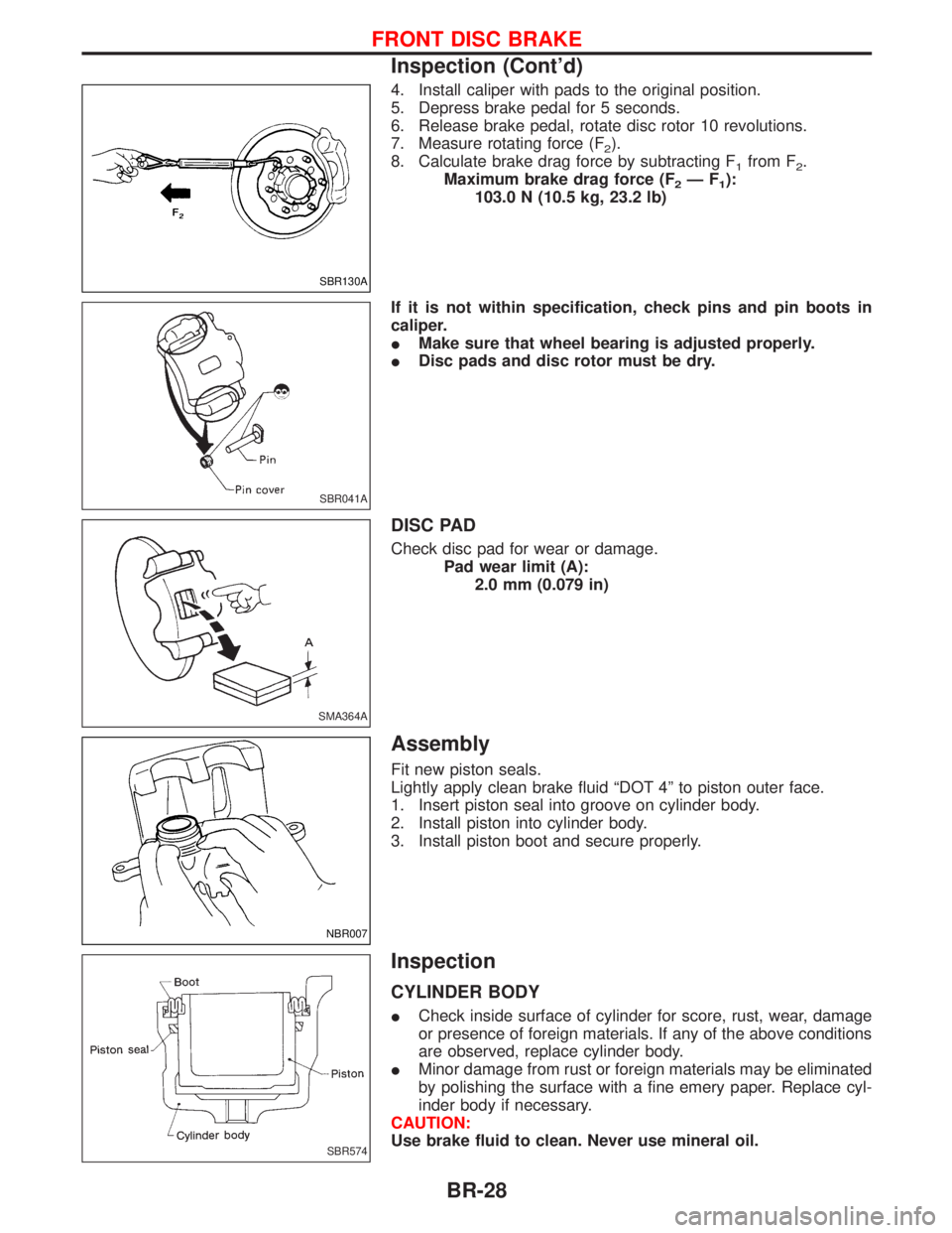
4. Install caliper with pads to the original position.
5. Depress brake pedal for 5 seconds.
6. Release brake pedal, rotate disc rotor 10 revolutions.
7. Measure rotating force (F
2).
8. Calculate brake drag force by subtracting F
1from F2.
Maximum brake drag force (F
2ÐF1):
103.0 N (10.5 kg, 23.2 lb)
If it is not within specification, check pins and pin boots in
caliper.
IMake sure that wheel bearing is adjusted properly.
IDisc pads and disc rotor must be dry.
DISC PAD
Check disc pad for wear or damage.
Pad wear limit (A):
2.0 mm (0.079 in)
Assembly
Fit new piston seals.
Lightly apply clean brake fluid ªDOT 4º to piston outer face.
1. Insert piston seal into groove on cylinder body.
2. Install piston into cylinder body.
3. Install piston boot and secure properly.
Inspection
CYLINDER BODY
ICheck inside surface of cylinder for score, rust, wear, damage
or presence of foreign materials. If any of the above conditions
are observed, replace cylinder body.
IMinor damage from rust or foreign materials may be eliminated
by polishing the surface with a fine emery paper. Replace cyl-
inder body if necessary.
CAUTION:
Use brake fluid to clean. Never use mineral oil.
SBR130A
SBR041A
SMA364A
NBR007
SBR574
FRONT DISC BRAKE
Inspection (Cont'd)
BR-28
Page 233 of 1767
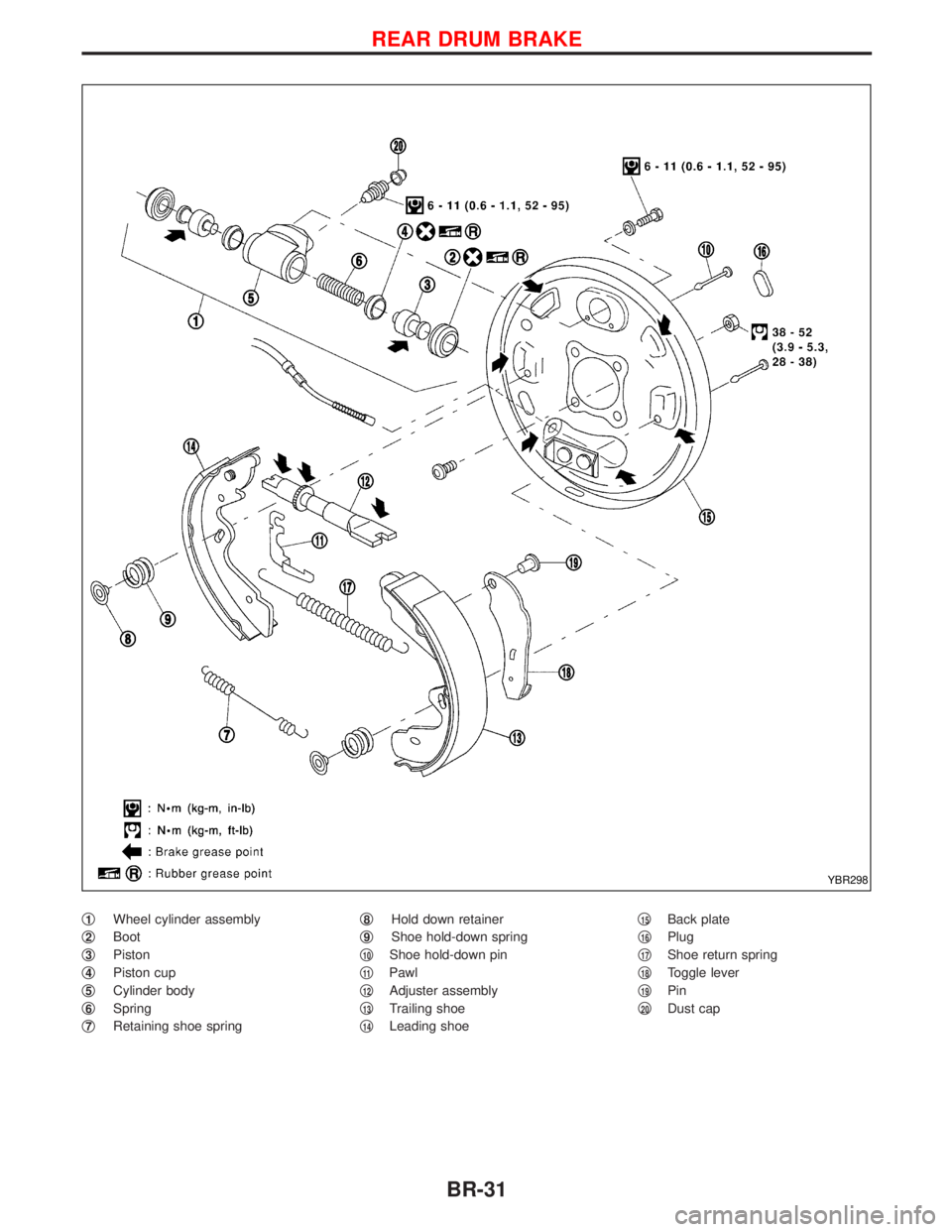
q1Wheel cylinder assembly
q
2Boot
q
3Piston
q
4Piston cup
q
5Cylinder body
q
6Spring
q
7Retaining shoe springq
8Hold down retainer
q
9Shoe hold-down spring
q
10Shoe hold-down pin
q
11Pawl
q
12Adjuster assembly
q
13Trailing shoe
q
14Leading shoeq
15Back plate
q
16Plug
q
17Shoe return spring
q
18Toggle lever
q
19Pin
q
20Dust cap
YBR298
REAR DRUM BRAKE
BR-31
Page 997 of 1767
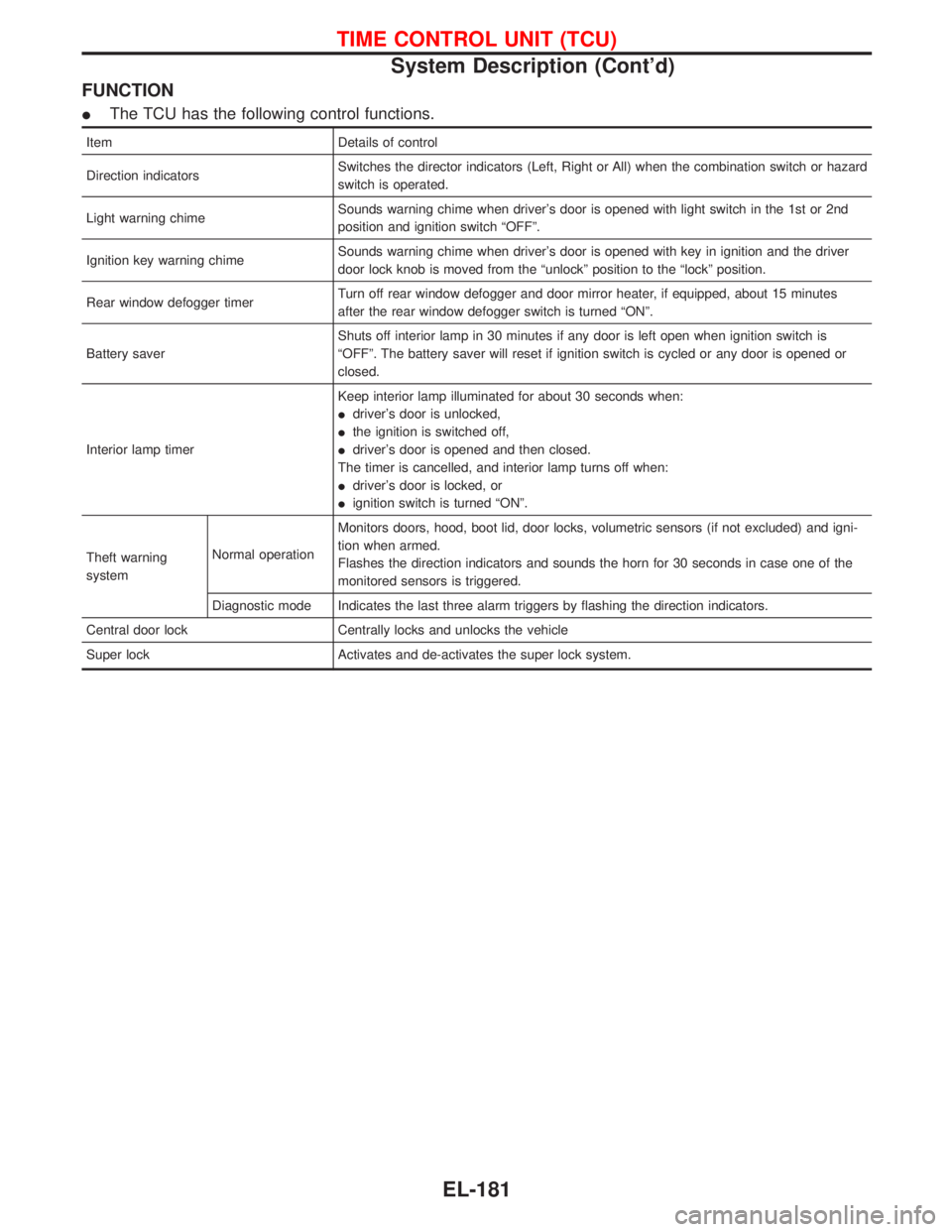
FUNCTION
IThe TCU has the following control functions.
Item Details of control
Direction indicatorsSwitches the director indicators (Left, Right or All) when the combination switch or hazard
switch is operated.
Light warning chimeSounds warning chime when driver's door is opened with light switch in the 1st or 2nd
position and ignition switch ªOFFº.
Ignition key warning chimeSounds warning chime when driver's door is opened with key in ignition and the driver
door lock knob is moved from the ªunlockº position to the ªlockº position.
Rear window defogger timerTurn off rear window defogger and door mirror heater, if equipped, about 15 minutes
after the rear window defogger switch is turned ªONº.
Battery saverShuts off interior lamp in 30 minutes if any door is left open when ignition switch is
ªOFFº. The battery saver will reset if ignition switch is cycled or any door is opened or
closed.
Interior lamp timerKeep interior lamp illuminated for about 30 seconds when:
Idriver's door is unlocked,
Ithe ignition is switched off,
Idriver's door is opened and then closed.
The timer is cancelled, and interior lamp turns off when:
Idriver's door is locked, or
Iignition switch is turned ªONº.
Theft warning
systemNormal operationMonitors doors, hood, boot lid, door locks, volumetric sensors (if not excluded) and igni-
tion when armed.
Flashes the direction indicators and sounds the horn for 30 seconds in case one of the
monitored sensors is triggered.
Diagnostic mode Indicates the last three alarm triggers by flashing the direction indicators.
Central door lock Centrally locks and unlocks the vehicle
Super lock Activates and de-activates the super lock system.
TIME CONTROL UNIT (TCU)
System Description (Cont'd)
EL-181
Page 1281 of 1767
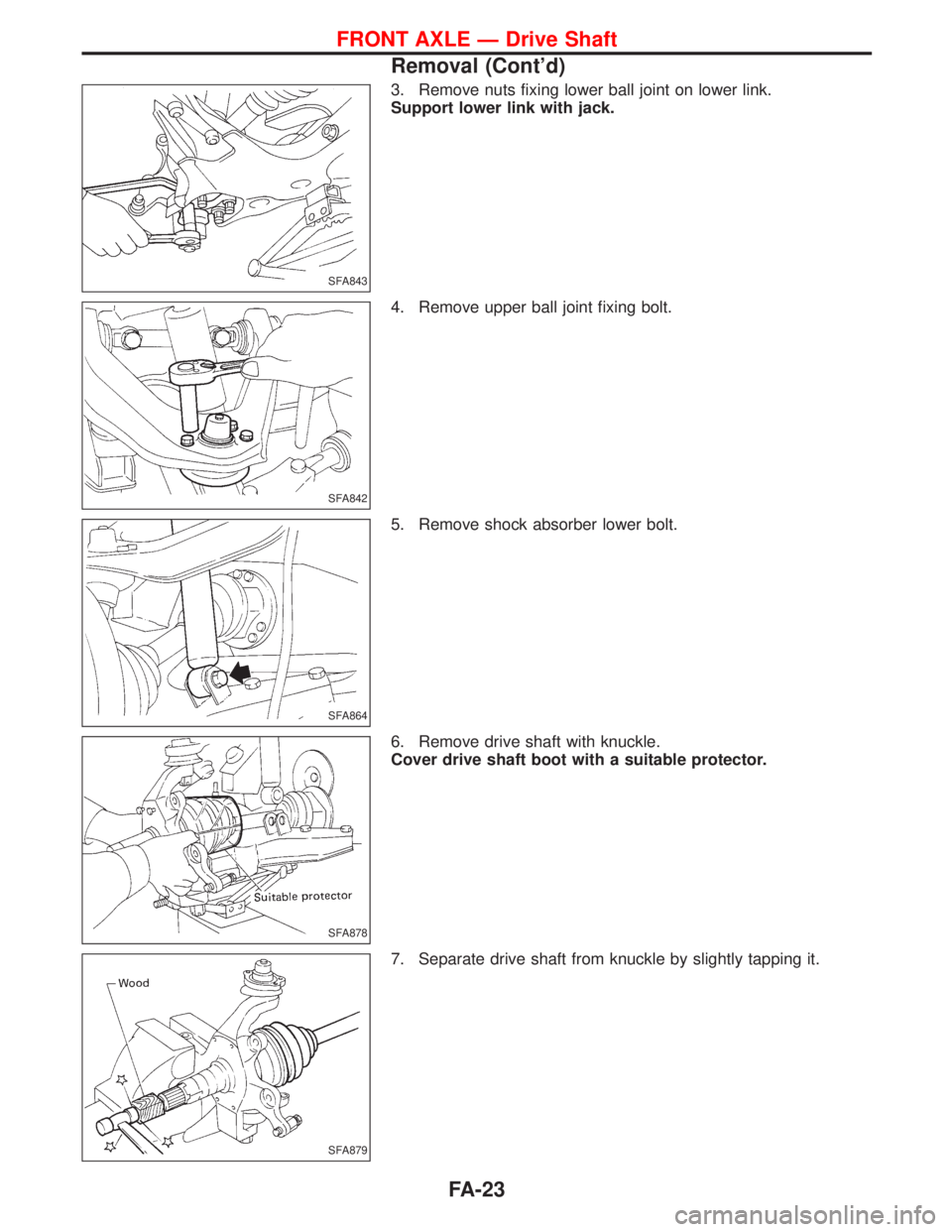
3. Remove nuts fixing lower ball joint on lower link.
Support lower link with jack.
4. Remove upper ball joint fixing bolt.
5. Remove shock absorber lower bolt.
6. Remove drive shaft with knuckle.
Cover drive shaft boot with a suitable protector.
7. Separate drive shaft from knuckle by slightly tapping it.
SFA843
SFA842
SFA864
SFA878
SFA879
FRONT AXLE Ð Drive Shaft
Removal (Cont'd)
FA-23
Page 1282 of 1767
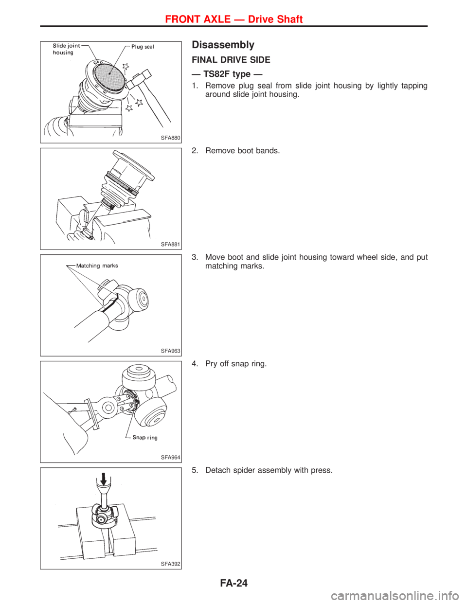
Disassembly
FINAL DRIVE SIDE
Ð TS82F type Ð
1. Remove plug seal from slide joint housing by lightly tapping
around slide joint housing.
2. Remove boot bands.
3. Move boot and slide joint housing toward wheel side, and put
matching marks.
4. Pry off snap ring.
5. Detach spider assembly with press.
SFA880
SFA881
SFA963
SFA964
SFA392
FRONT AXLE Ð Drive Shaft
FA-24
Page 1283 of 1767
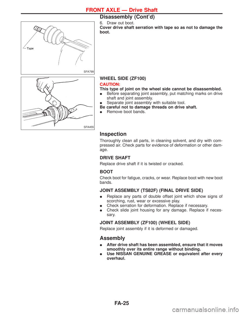
6. Draw out boot.
Cover drive shaft serration with tape so as not to damage the
boot.
WHEEL SIDE (ZF100)
CAUTION:
This type of joint on the wheel side cannot be disassembled.
IBefore separating joint assembly, put matching marks on drive
shaft and joint assembly.
ISeparate joint assembly with suitable tool.
Be careful not to damage threads on drive shaft.
IRemove boot bands.
Inspection
Thoroughly clean all parts, in cleaning solvent, and dry with com-
pressed air. Check parts for evidence of deformation or other dam-
age.
DRIVE SHAFT
Replace drive shaft if it is twisted or cracked.
BOOT
Check boot for fatigue, cracks, or wear. Replace boot with new boot
bands.
JOINT ASSEMBLY (TS82F) (FINAL DRIVE SIDE)
IReplace any parts of double offset joint which show signs of
scorching, rust, wear or excessive play.
ICheck serration for deformation. Replace if necessary.
ICheck slide joint housing for any damage. Replace if neces-
sary.
JOINT ASSEMBLY (ZF100) (WHEEL SIDE)
Replace joint assembly if it is deformed or damaged.
Assembly
IAfter drive shaft has been assembled, ensure that it moves
smoothly over its entire range without binding.
IUse NISSAN GENUINE GREASE or equivalent after every
overhaul.
SFA799
SFA455
FRONT AXLE Ð Drive Shaft
Disassembly (Cont'd)
FA-25
Page 1284 of 1767
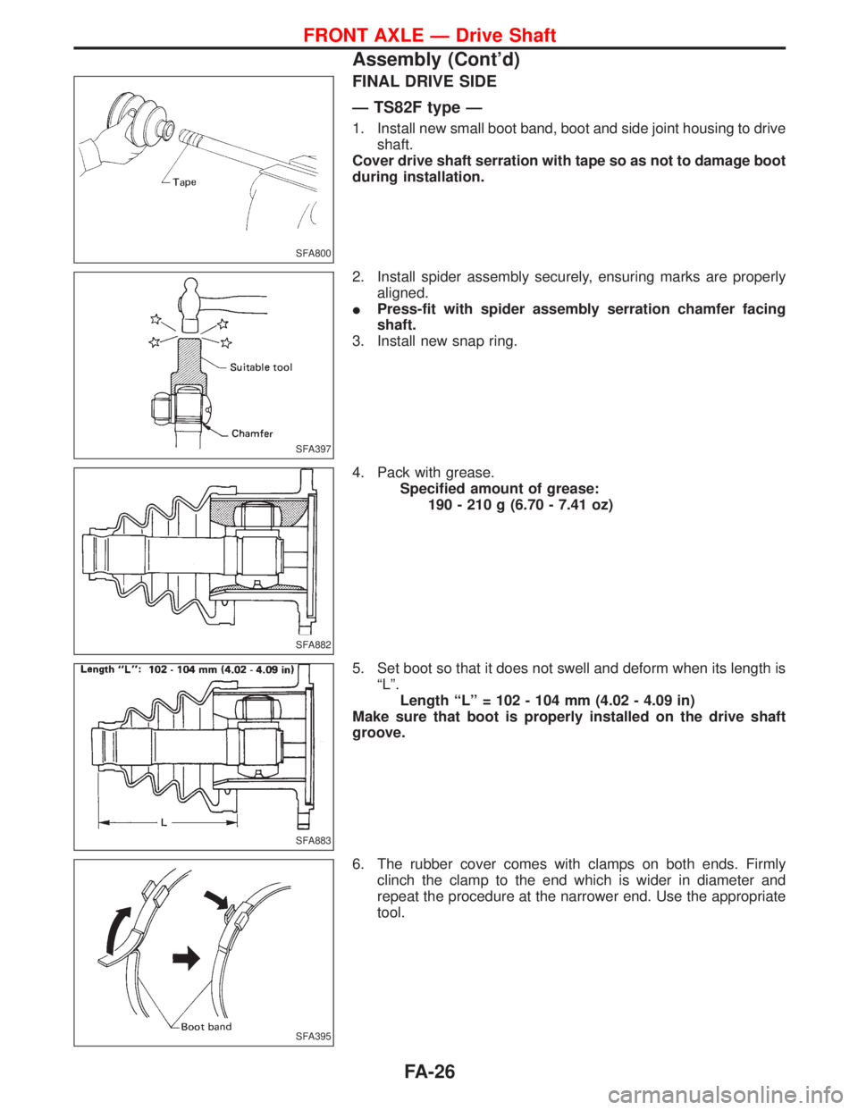
FINAL DRIVE SIDE
Ð TS82F type Ð
1. Install new small boot band, boot and side joint housing to drive
shaft.
Cover drive shaft serration with tape so as not to damage boot
during installation.
2. Install spider assembly securely, ensuring marks are properly
aligned.
IPress-fit with spider assembly serration chamfer facing
shaft.
3. Install new snap ring.
4. Pack with grease.
Specified amount of grease:
190 - 210 g (6.70 - 7.41 oz)
5. Set boot so that it does not swell and deform when its length is
ªLº.
Length ªLº = 102 - 104 mm (4.02 - 4.09 in)
Make sure that boot is properly installed on the drive shaft
groove.
6. The rubber cover comes with clamps on both ends. Firmly
clinch the clamp to the end which is wider in diameter and
repeat the procedure at the narrower end. Use the appropriate
tool.
SFA800
SFA397
SFA882
SFA883
SFA395
FRONT AXLE Ð Drive Shaft
Assembly (Cont'd)
FA-26
Page 1285 of 1767
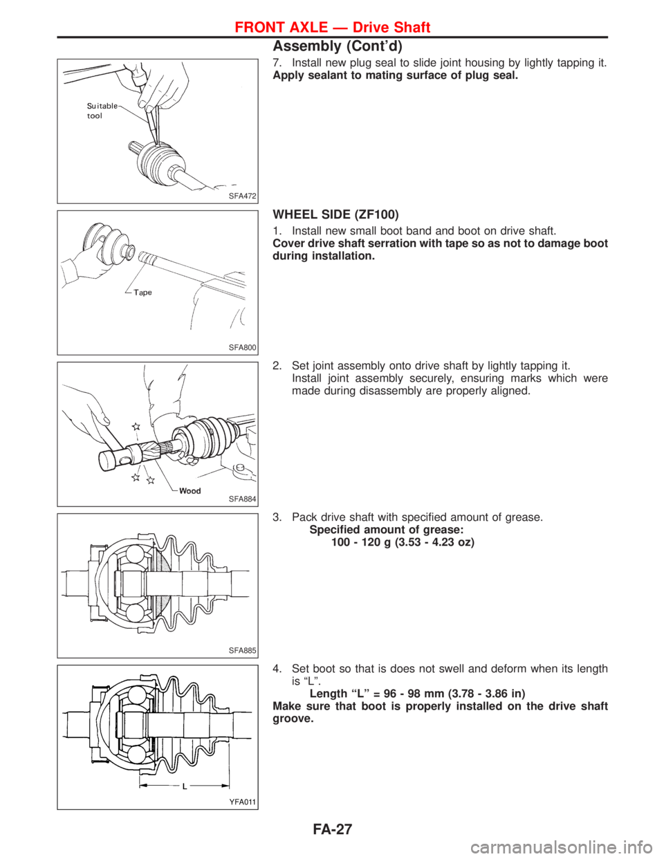
7. Install new plug seal to slide joint housing by lightly tapping it.
Apply sealant to mating surface of plug seal.
WHEEL SIDE (ZF100)
1. Install new small boot band and boot on drive shaft.
Cover drive shaft serration with tape so as not to damage boot
during installation.
2. Set joint assembly onto drive shaft by lightly tapping it.
Install joint assembly securely, ensuring marks which were
made during disassembly are properly aligned.
3. Pack drive shaft with specified amount of grease.
Specified amount of grease:
100 - 120 g (3.53 - 4.23 oz)
4. Set boot so that is does not swell and deform when its length
is ªLº.
Length ªLº = 96 - 98 mm (3.78 - 3.86 in)
Make sure that boot is properly installed on the drive shaft
groove.
SFA472
SFA800
SFA884
SFA885
YFA011
FRONT AXLE Ð Drive Shaft
Assembly (Cont'd)
FA-27
Page 1286 of 1767
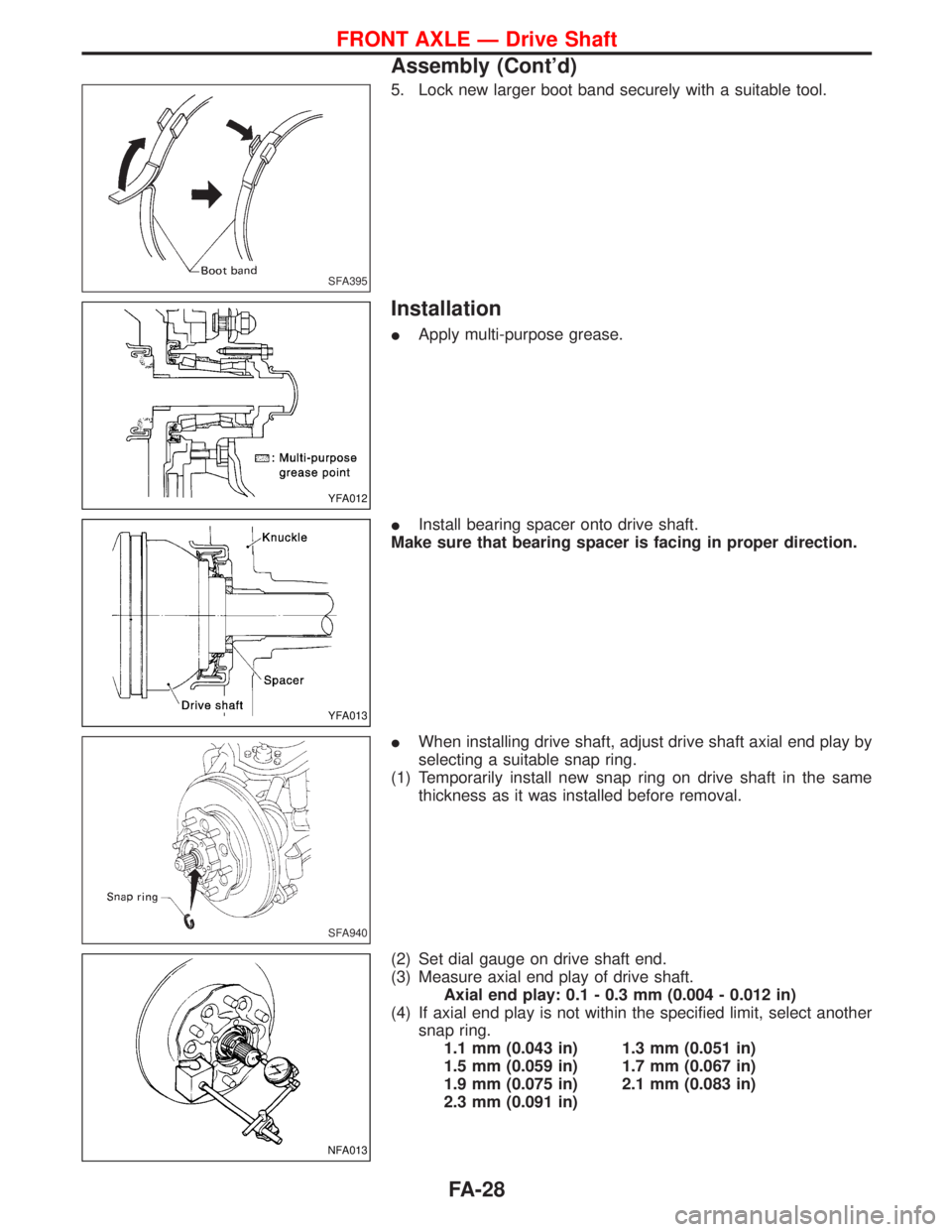
5. Lock new larger boot band securely with a suitable tool.
Installation
IApply multi-purpose grease.
IInstall bearing spacer onto drive shaft.
Make sure that bearing spacer is facing in proper direction.
IWhen installing drive shaft, adjust drive shaft axial end play by
selecting a suitable snap ring.
(1) Temporarily install new snap ring on drive shaft in the same
thickness as it was installed before removal.
(2) Set dial gauge on drive shaft end.
(3) Measure axial end play of drive shaft.
Axial end play: 0.1 - 0.3 mm (0.004 - 0.012 in)
(4) If axial end play is not within the specified limit, select another
snap ring.
1.1 mm (0.043 in) 1.3 mm (0.051 in)
1.5 mm (0.059 in) 1.7 mm (0.067 in)
1.9 mm (0.075 in) 2.1 mm (0.083 in)
2.3 mm (0.091 in)
SFA395
YFA012
YFA013
SFA940
NFA013
FRONT AXLE Ð Drive Shaft
Assembly (Cont'd)
FA-28
Page 1296 of 1767
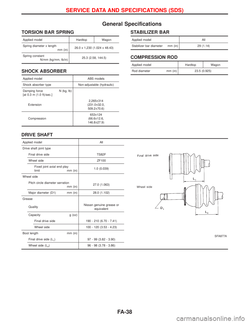
General Specifications
TORSION BAR SPRING
Applied model Hardtop Wagon
Spring diameter x length
mm (in)26.0 x 1,230 (1.024 x 48.43)
Spring constant
N/mm (kg/mm, lb/in)25.3 (2.58, 144.5)
SHOCK ABSORBER
Applied model ABS models
Shock absorber type Non-adjustable (hydraulic)
Damping force N (kg, lb)
[at 0.3 m (1.0 ft)/sec.]
Extension2,265 314
(231.0 32.0,
509.2 70.6)
Compression653 124
(66.6 12.6,
146.8 27.9)
STABILIZER BAR
Applied model All
Stabilizer bar diameter mm (in) 29 (1.14)
COMPRESSION ROD
Applied model Hardtop Wagon
Rod diameter mm (in) 23.5 (0.925)
DRIVE SHAFT
Applied model All
SFA877A
Drive shaft joint type
Final drive side TS82F
Wheel side ZF100
Fixed joint axial end play
limit mm (in)1.0 (0.039)
Wheel side
Pitch circle diameter serration
mm (in)27.0 (1.063)
Major diameter (D1) mm (in) 28.0 (1.102)
Grease
QualityNissan genuine grease or
equivalent
Capacity g (oz)
Final drive side 190 - 210 (6.70 - 7.41)
Wheel side 100 - 120 (3.53 - 4.23)
Boot length mm (in)
Final drive side (L
1) 97 - 99 (3.82 - 3.90)
Wheel side (L
2) 96 - 98 (3.78 - 3.86)
SERVICE DATA AND SPECIFICATIONS (SDS)
FA-38