key battery NISSAN TERRANO 2002 Service Repair Manual
[x] Cancel search | Manufacturer: NISSAN, Model Year: 2002, Model line: TERRANO, Model: NISSAN TERRANO 2002Pages: 1767, PDF Size: 41.51 MB
Page 396 of 1767
IIf the battery is disconnected, the emission-related diagnostic information will be lost after approx.
24 hours.
IErasing the emission-related diagnostic information using CONSULT-II is easier and quicker than
switching the diagnostic test mode using the data link connector.
NATS (Nissan Anti-Theft System)
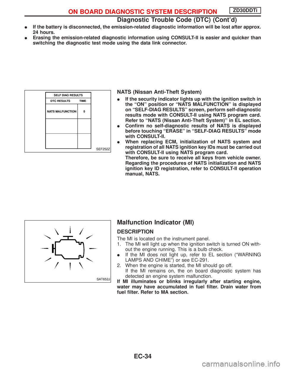
IIf the security indicator lights up with the ignition switch in
the ªONº position or ªNATS MALFUNCTIONº is displayed
on ªSELF-DIAG RESULTSº screen, perform self-diagnostic
results mode with CONSULT-II using NATS program card.
Refer to ªNATS (Nissan Anti-Theft System)º in EL section.
IConfirm no self-diagnostic results of NATS is displayed
before touching ªERASEº in ªSELF-DIAG RESULTSº mode
with CONSULT-II.
IWhen replacing ECM, initialization of NATS system and
registration of all NATS ignition key IDs must be carried out
with CONSULT-II using NATS program card.
Therefore, be sure to receive all keys from vehicle owner.
Regarding the procedures of NATS initialization and NATS
ignition key ID registration, refer to CONSULT-II operation
manual, NATS.
Malfunction Indicator (MI)
DESCRIPTION
The MI is located on the instrument panel.
1. The MI will light up when the ignition switch is turned ON with-
out the engine running. This is a bulb check.
IIf the MI does not light up, refer to EL section (ªWARNING
LAMPS AND CHIMEº) or see EC-291.
2. When the engine is started, the MI should go off.
If the MI remains on, the on board diagnostic system has
detected an engine system malfunction.
If MI illuminates or blinks irregularly after starting engine,
water may have accumulated in fuel filter. Drain water from
fuel filter. Refer to MA section.
SEF252Z
SAT652J
ON BOARD DIAGNOSTIC SYSTEM DESCRIPTIONZD30DDTi
Diagnostic Trouble Code (DTC) (Cont'd)
EC-34
Page 680 of 1767
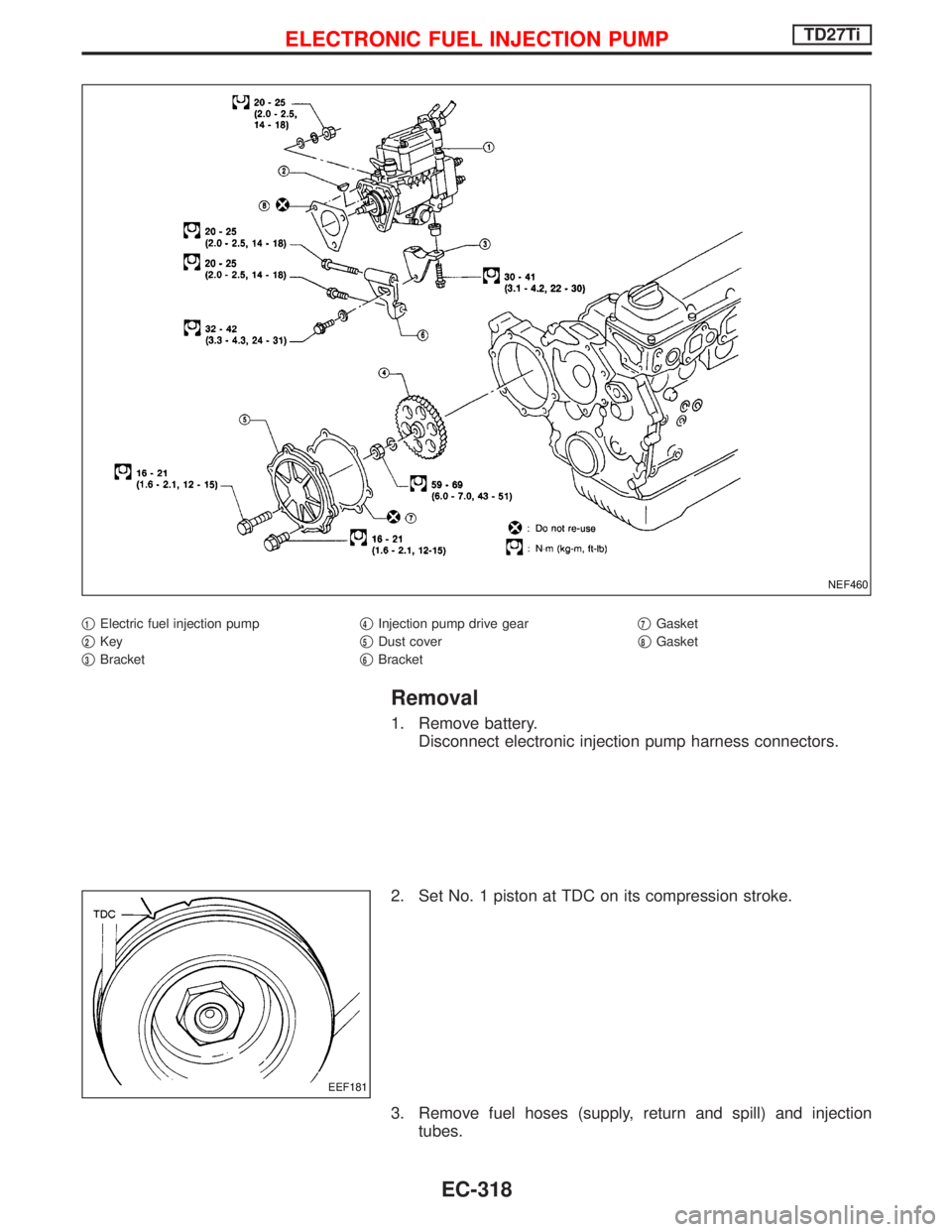
q1Electric fuel injection pump
q
2Key
q
3Bracketq
4Injection pump drive gear
q
5Dust cover
q
6Bracketq
7Gasket
q
8Gasket
Removal
1. Remove battery.
Disconnect electronic injection pump harness connectors.
2. Set No. 1 piston at TDC on its compression stroke.
3. Remove fuel hoses (supply, return and spill) and injection
tubes.
NEF460
EEF181
ELECTRONIC FUEL INJECTION PUMPTD27Ti
EC-318
Page 684 of 1767
How to Erase DTC (Without CONSULT-II)
1. If the ignition switch stays ªONº after repair work, be sure to turn ignition switch ªOFFº once. Wait at least
5 seconds and then turn it ªONº (engine stopped) again.
2. Change the diagnostic test mode from Mode II to Mode I by using the data link connector. (See EC-323.)
The emission related diagnostic information in the ECM can be erased by changing the diagnostic test mode.
IIf the battery is disconnected, the emission-related diagnostic information will be lost after approx.
24 hours.
IErasing the emission-related diagnostic information using CONSULT-II is easier and quicker than
switching the diagnostic test mode using the data link connector.
Malfunction Indicator (MI)
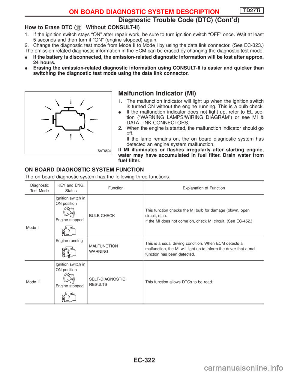
1. The malfunction indicator will light up when the ignition switch
is turned ON without the engine running. This is a bulb check.
IIf the malfunction indicator does not light up, refer to EL sec-
tion (ªWARNING LAMPS/WIRING DIAGRAMº) or see MI &
DATA LINK CONNECTORS.
2. When the engine is started, the malfunction indicator should go
off.
If the lamp remains on, the on board diagnostic system has
detected an engine system malfunction.
If MI illuminates or flashes irregularly after starting engine,
water may have accumulated in fuel filter. Drain water from
fuel filter.
ON BOARD DIAGNOSTIC SYSTEM FUNCTION
The on board diagnostic system has the following three functions.
Diagnostic
Test ModeKEY and ENG.
StatusFunction Explanation of Function
Mode IIgnition switch in
ON position
Engine stoppedBULB CHECKThis function checks the MI bulb for damage (blown, open
circuit, etc.).
If the MI does not come on, check MI circuit. (See EC-452.)
Engine running
MALFUNCTION
WARNINGThis is a usual driving condition. When ECM detects a
malfunction, the MI will light up to inform the driver that a mal-
function has been detected.
Mode IIIgnition switch in
ON position
Engine stopped
SELF-DIAGNOSTIC
RESULTSThis function allows DTCs to be read.
SAT652J
ON BOARD DIAGNOSTIC SYSTEM DESCRIPTIONTD27Ti
Diagnostic Trouble Code (DTC) (Cont'd)
EC-322
Page 686 of 1767
DIAGNOSTIC TEST MODE IÐBULB CHECK
In this mode, the MALFUNCTION INDICATOR on the instrument panel should stay ON. If it remains OFF,
check the bulb. Refer to EL section (ªWARNING LAMPS/WIRING DIAGRAMº) or see EC-452.
DIAGNOSTIC TEST MODE IÐMALFUNCTION WARNING
MI Condition
ON When a malfunction is detected or the ECM's CPU is malfunctioning.
OFF No malfunction.
IThese Diagnostic Trouble Code Numbers are clarified in Diagnostic Test Mode II (SELF-DIAGNOSTIC
RESULTS).
DIAGNOSTIC TEST MODE IIÐSELF-DIAGNOSTIC RESULTS
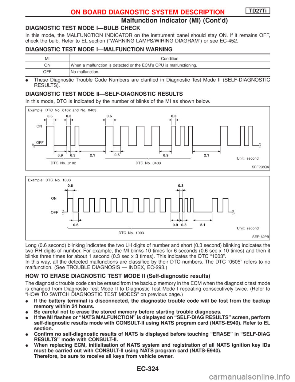
In this mode, DTC is indicated by the number of blinks of the MI as shown below.
Long (0.6 second) blinking indicates the two LH digits of number and short (0.3 second) blinking indicates the
two RH digits of number. For example, the MI blinks 10 times for 6 seconds (0.6 sec x 10 times) and then it
blinks three times for about 1 second (0.3 sec x 3 times). This indicates the DTC ª1003º.
In this way, all the detected malfunctions are classified by their DTC numbers. The DTC ª0505º refers to no
malfunction. (See TROUBLE DIAGNOSIS Ð INDEX, EC-293.)
HOW TO ERASE DIAGNOSTIC TEST MODE II (Self-diagnostic results)
The diagnostic trouble code can be erased from the backup memory in the ECM when the diagnostic test mode
is changed from Diagnostic Test Mode II to Diagnostic Test Mode I repeating consecutively twice. (Refer to
ªHOW TO SWITCH DIAGNOSTIC TEST MODESº on previous page.)
IIf the battery terminal is disconnected, the diagnostic trouble code will be lost from the backup
memory within 24 hours.
IBe careful not to erase the stored memory before starting trouble diagnoses.
IIf the MI flashes or ªNATS MALFUNCTIONº is displayed on ªSELF-DIAG RESULTSº screen, perform
self-diagnostic results mode with CONSULT-II using NATS program card (NATS-E940). Refer to EL
section.
IConfirm no self-diagnostic results of NATS is displayed before touching ªERASEº in ªSELF-DIAG
RESULTSº mode with CONSULT-II.
IWhen replacing ECM, initialisation of NATS system and registration of all NATS ignition key IDs
must be carried out with CONSULT-II using NATS program card (NATS-E940).
Therefore, be sure to receive all keys from vehicle owner.
SEF298QA
SEF162PB
ON BOARD DIAGNOSTIC SYSTEM DESCRIPTIONTD27Ti
Malfunction Indicator (MI) (Cont'd)
EC-324
Page 963 of 1767
Key reminder system
IIf the ignition key is in the ignition cylinder and any door is open, setting the lock & unlock switch and lock
knob on driver door to ªLOCKº locks the door once but then immediately unlocks it.
System initialisation
ISystem initialisation is required when battery cables are reconnected. Conduct one of the following:
Ð insert the key into ignition key cylinder and turn it to ªON.º
Ð LOCK/UNLOCK operation using door key cylinder.
POWER DOOR LOCK Ð SUPER LOCK Ð
System Description (Cont'd)
EL-147
Page 983 of 1767
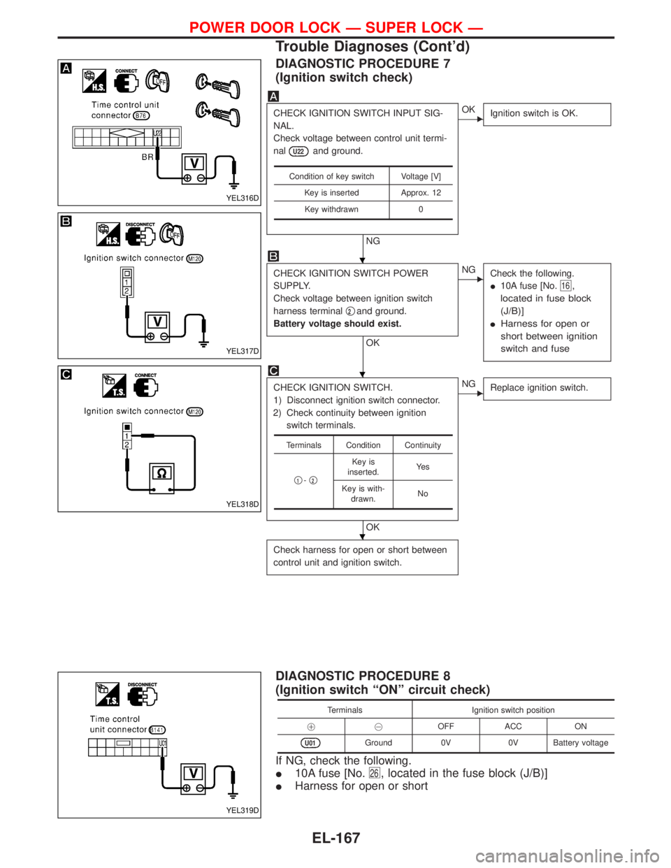
DIAGNOSTIC PROCEDURE 7
(Ignition switch check)
CHECK IGNITION SWITCH INPUT SIG-
NAL.
Check voltage between control unit termi-
nal
U22and ground.
NG
EOK
Ignition switch is OK.
CHECK IGNITION SWITCH POWER
SUPPLY.
Check voltage between ignition switch
harness terminalq
2and ground.
Battery voltage should exist.
OK
ENG
Check the following.
I10A fuse [No.
16,
located in fuse block
(J/B)]
IHarness for open or
short between ignition
switch and fuse
CHECK IGNITION SWITCH.
1) Disconnect ignition switch connector.
2) Check continuity between ignition
switch terminals.
OK
ENG
Replace ignition switch.
Check harness for open or short between
control unit and ignition switch.
Condition of key switch Voltage [V]
Key is inserted Approx. 12
Key withdrawn 0
Terminals Condition Continuity
q
1-q2
Key is
inserted.Ye s
Key is with-
drawn.No
DIAGNOSTIC PROCEDURE 8
(Ignition switch ªONº circuit check)
Terminals Ignition switch position
!@OFF ACC ON
U01Ground 0V 0V Battery voltage
If NG, check the following.
I10A fuse [No.
26, located in the fuse block (J/B)]
IHarness for open or short
YEL316D
YEL317D
YEL318D
YEL319D
H
H
H
POWER DOOR LOCK Ð SUPER LOCK Ð
Trouble Diagnoses (Cont'd)
EL-167
Page 993 of 1767
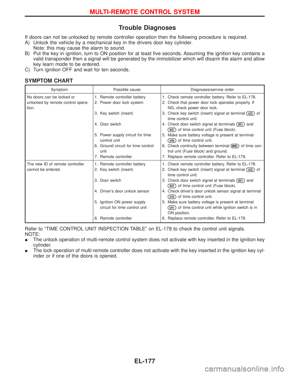
Trouble Diagnoses
If doors can not be unlocked by remote controller operation then the following procedure is required.
A) Unlock the vehicle by a mechanical key in the drivers door key cylinder.
Note: this may cause the alarm to sound.
B) Put the key in ignition, turn to ON position for at least five seconds. Assuming the ignition key contains a
valid transponder then a signal will be generated by the immobilizer which will disarm the alarm and allow
key learn mode to be entered.
C) Turn ignition OFF and wait for ten seconds.
SYMPTOM CHART
Symptom Possible cause Diagnoses/service order
No doors can be locked or
unlocked by remote control opera-
tion.1. Remote controller battery
2. Power door lock system
3. Key switch (insert)
4. Door switch
5. Power supply circuit for time
control unit
6. Ground circuit for time control
unit
7. Remote controller1. Check remote controller battery. Refer to EL-178.
2. Check that power door lock operates properly. If
NG, check power door lock.
3. Check key switch (insert) signal at terminal
U22of
time control unit.
4. Check door switch signal at terminals
B01and
B07of time control unit (Fuse block).
5. Make sure battery voltage is present at terminal
U09of time control unit.
6. Check continuity between terminal
MM2of time con-
trol unit (Fuse block) and ground.
7. Replace remote controller. Refer to EL-179.
The new ID of remote controller
cannot be entered.1. Remote controller battery
2. Key switch (insert)
3. Door switch
4. Driver's door unlock sensor
5. Ignition ON power supply
circuit for time control unit
6. Remote controller1. Check remote controller battery. Refer to EL-178.
2. Check key switch (insert) signal at terminal
U22of
time control unit.
3. Check door switch signal at terminals
B01and
B07of time control unit (Fuse block).
4. Check driver's door unlock sensor signal at terminal
U35of time control unit.
5. Make sure battery voltage is present at terminal
U01of time control unit while ignition switch is in
ON position.
6. Replace remote controller. Refer to EL-179.
Refer to ªTIME CONTROL UNIT INSPECTION TABLEº on EL-178 to check the control unit signals.
NOTE:
IThe unlock operation of multi-remote control system does not activate with key inserted in the ignition key
cylinder.
IThe lock operation of multi-remote controller does not activate with the key inserted in the ignition key cyl-
inder or if one of the doors is opened.
MULTI-REMOTE CONTROL SYSTEM
EL-177
Page 994 of 1767
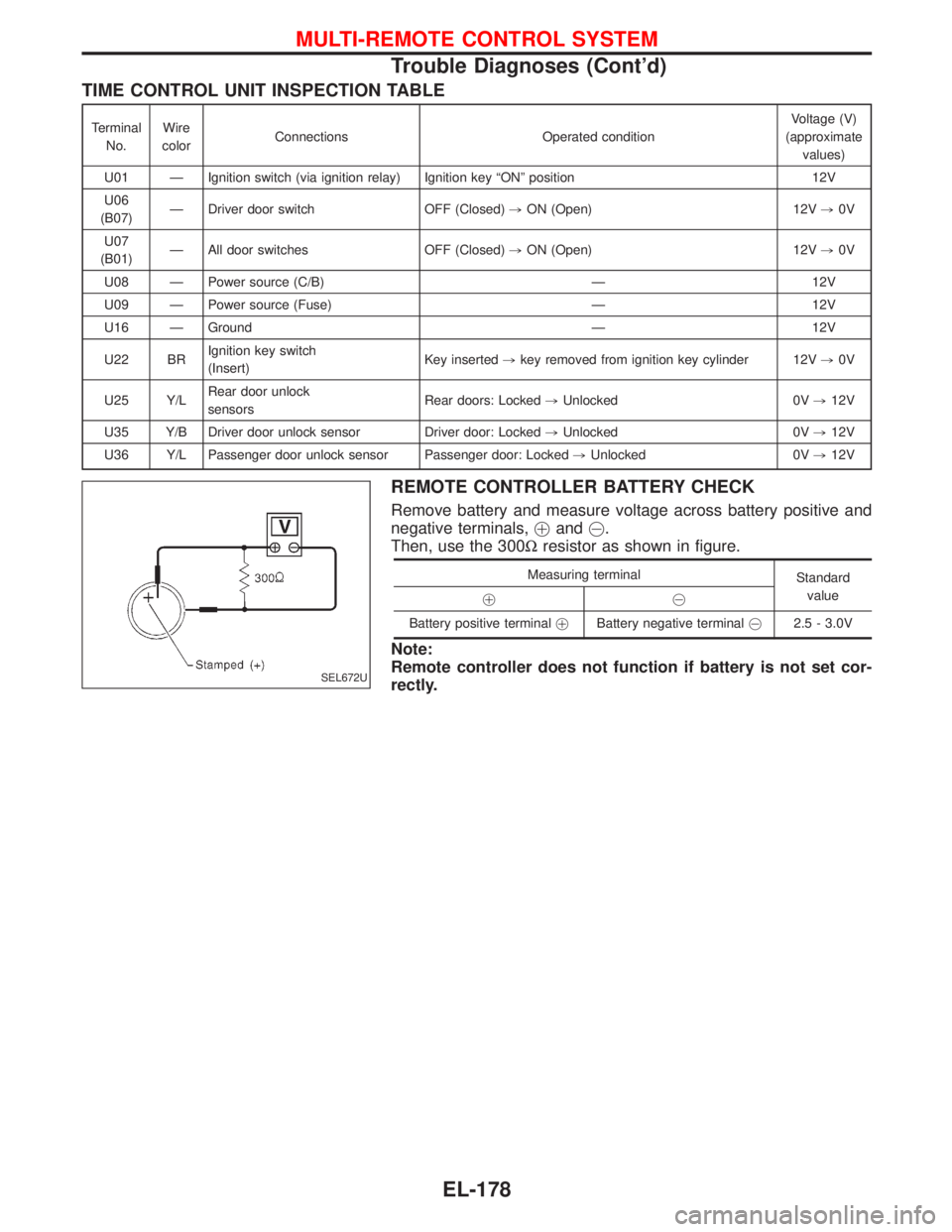
TIME CONTROL UNIT INSPECTION TABLE
Terminal
No.Wire
colorConnections Operated conditionVoltage (V)
(approximate
values)
U01 Ð Ignition switch (via ignition relay) Ignition key ªONº position 12V
U06
(B07)Ð Driver door switch OFF (Closed),ON (Open) 12V,0V
U07
(B01)Ð All door switches OFF (Closed),ON (Open) 12V,0V
U08 Ð Power source (C/B) Ð 12V
U09 Ð Power source (Fuse) Ð 12V
U16 Ð Ground Ð 12V
U22 BRIgnition key switch
(Insert)Key inserted,key removed from ignition key cylinder 12V,0V
U25 Y/LRear door unlock
sensorsRear doors: Locked,Unlocked 0V,12V
U35 Y/B Driver door unlock sensor Driver door: Locked,Unlocked 0V,12V
U36 Y/L Passenger door unlock sensor Passenger door: Locked,Unlocked 0V,12V
REMOTE CONTROLLER BATTERY CHECK
Remove battery and measure voltage across battery positive and
negative terminals,!and@.
Then, use the 300Wresistor as shown in figure.
Measuring terminal
Standard
value
!@
Battery positive terminal!Battery negative [email protected] - 3.0V
Note:
Remote controller does not function if battery is not set cor-
rectly.
SEL672U
MULTI-REMOTE CONTROL SYSTEM
Trouble Diagnoses (Cont'd)
EL-178
Page 995 of 1767
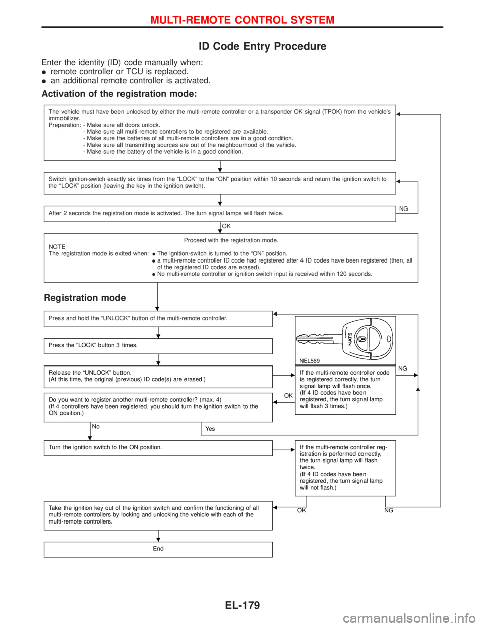
ID Code Entry Procedure
Enter the identity (ID) code manually when:
Iremote controller or TCU is replaced.
Ian additional remote controller is activated.
Activation of the registration mode:
The vehicle must have been unlocked by either the multi-remote controller or a transponder OK signal (TPOK) from the vehicle's
immobilizer.
Preparation: - Make sure all doors unlock.
- Make sure all multi-remote controllers to be registered are available.
- Make sure the batteries of all multi-remote controllers are in a good condition.
- Make sure all transmitting sources are out of the neighbourhood of the vehicle.
- Make sure the battery of the vehicle is in a good condition.F
Switch ignition-switch exactly six times from the ªLOCKº to the ªONº position within 10 seconds and return the ignition switch to
the ªLOCKº position (leaving the key in the ignition switch).F
After 2 seconds the registration mode is activated. The turn signal lamps will flash twice.
OKNG
Proceed with the registration mode.
NOTE
The registration mode is exited when:IThe ignition-switch is turned to the ªONº position.
Ia multi-remote controller ID code had registered after 4 ID codes have been registered (then, all
of the registered ID codes are erased).
INo multi-remote controller or ignition switch input is received within 120 seconds.
Registration mode
G
Press and hold the ªUNLOCKº button of the multi-remote controller.F
NEL569
Press the ªLOCKº button 3 times.
Release the ªUNLOCKº button.
(At this time, the original (previous) ID code(s) are erased.)EIf the multi-remote controller code
is registered correctly, the turn
signal lamp will flash once.
(If 4 ID codes have been
registered, the turn signal lamp
will flash 3 times.)ENG
Do you want to register another multi-remote controller? (max. 4)
(If 4 controllers have been registered, you should turn the ignition switch to the
ON position.)
NoYe s
FOK
Turn the ignition switch to the ON position.
EIf the multi-remote controller reg-
istration is performed correctly,
the turn signal lamp will flash
twice.
(If 4 ID codes have been
registered, the turn signal lamp
will not flash.)
Take the ignition key out of the ignition switch and confirm the functioning of all
multi-remote controllers by locking and unlocking the vehicle with each of the
multi-remote controllers.OK NGF
End
H
H
H
H
H
H
H
H
MULTI-REMOTE CONTROL SYSTEM
EL-179
Page 997 of 1767
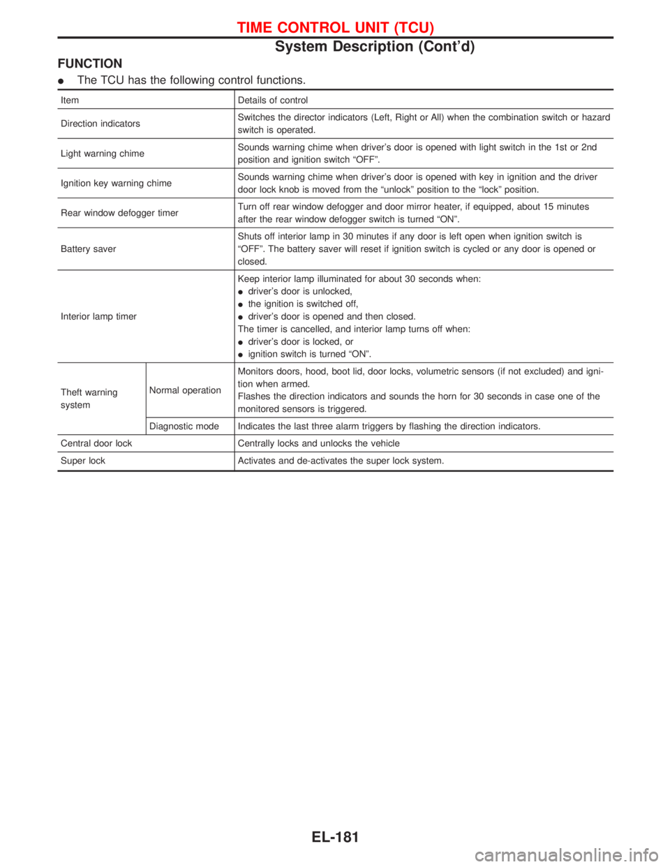
FUNCTION
IThe TCU has the following control functions.
Item Details of control
Direction indicatorsSwitches the director indicators (Left, Right or All) when the combination switch or hazard
switch is operated.
Light warning chimeSounds warning chime when driver's door is opened with light switch in the 1st or 2nd
position and ignition switch ªOFFº.
Ignition key warning chimeSounds warning chime when driver's door is opened with key in ignition and the driver
door lock knob is moved from the ªunlockº position to the ªlockº position.
Rear window defogger timerTurn off rear window defogger and door mirror heater, if equipped, about 15 minutes
after the rear window defogger switch is turned ªONº.
Battery saverShuts off interior lamp in 30 minutes if any door is left open when ignition switch is
ªOFFº. The battery saver will reset if ignition switch is cycled or any door is opened or
closed.
Interior lamp timerKeep interior lamp illuminated for about 30 seconds when:
Idriver's door is unlocked,
Ithe ignition is switched off,
Idriver's door is opened and then closed.
The timer is cancelled, and interior lamp turns off when:
Idriver's door is locked, or
Iignition switch is turned ªONº.
Theft warning
systemNormal operationMonitors doors, hood, boot lid, door locks, volumetric sensors (if not excluded) and igni-
tion when armed.
Flashes the direction indicators and sounds the horn for 30 seconds in case one of the
monitored sensors is triggered.
Diagnostic mode Indicates the last three alarm triggers by flashing the direction indicators.
Central door lock Centrally locks and unlocks the vehicle
Super lock Activates and de-activates the super lock system.
TIME CONTROL UNIT (TCU)
System Description (Cont'd)
EL-181