lights NISSAN TERRANO 2002 Service Repair Manual
[x] Cancel search | Manufacturer: NISSAN, Model Year: 2002, Model line: TERRANO, Model: NISSAN TERRANO 2002Pages: 1767, PDF Size: 41.51 MB
Page 95 of 1767
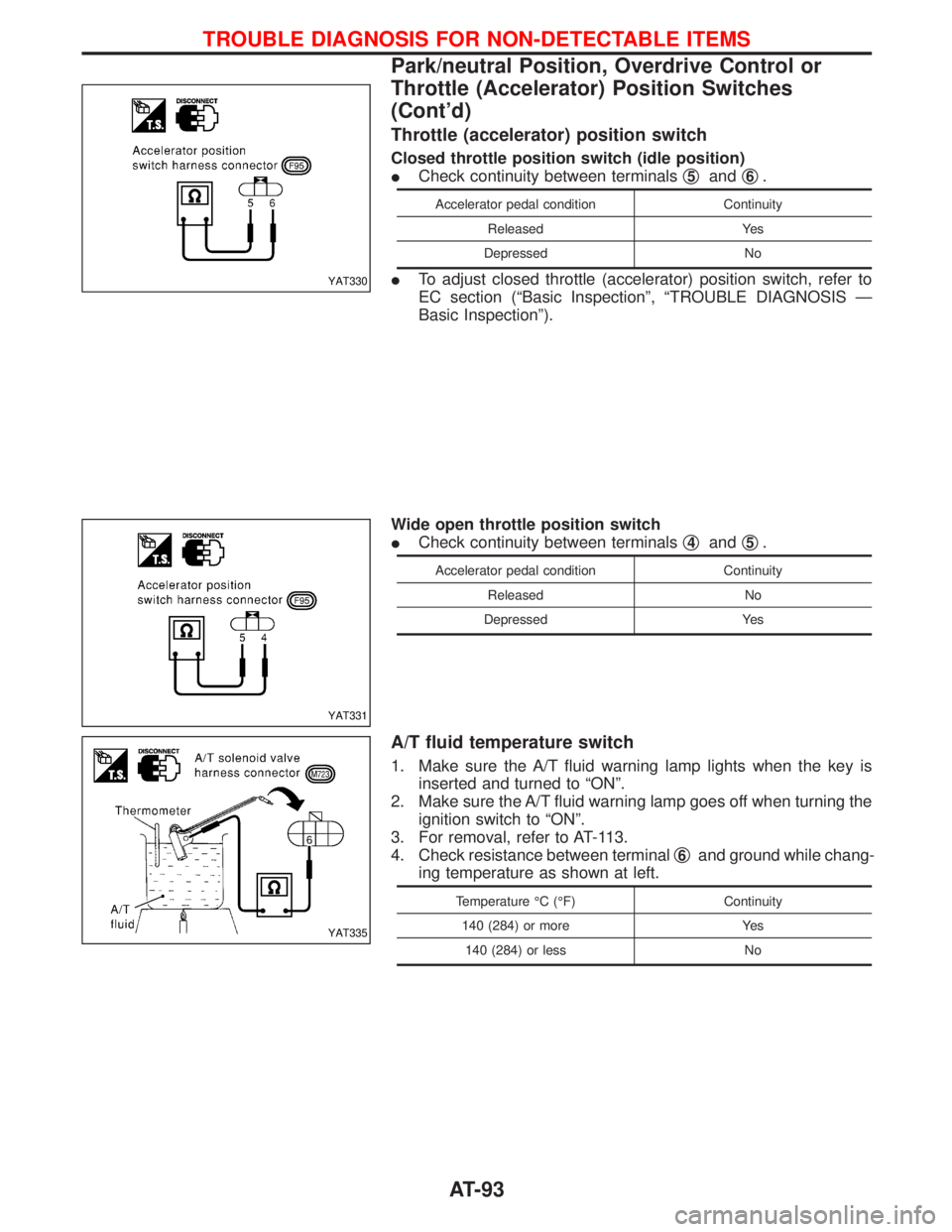
Throttle (accelerator) position switch
Closed throttle position switch (idle position)
ICheck continuity between terminalsq
5andq6.
Accelerator pedal condition Continuity
Released Yes
Depressed No
ITo adjust closed throttle (accelerator) position switch, refer to
EC section (ªBasic Inspectionº, ªTROUBLE DIAGNOSIS Ð
Basic Inspectionº).
Wide open throttle position switch
ICheck continuity between terminalsq
4andq5.
Accelerator pedal condition Continuity
Released No
Depressed Yes
A/T fluid temperature switch
1. Make sure the A/T fluid warning lamp lights when the key is
inserted and turned to ªONº.
2. Make sure the A/T fluid warning lamp goes off when turning the
ignition switch to ªONº.
3. For removal, refer to AT-113.
4. Check resistance between terminalq
6and ground while chang-
ing temperature as shown at left.
Temperature ÉC (ÉF) Continuity
140 (284) or more Yes
140 (284) or less No
YAT330
YAT331
YAT335
TROUBLE DIAGNOSIS FOR NON-DETECTABLE ITEMS
Park/neutral Position, Overdrive Control or
Throttle (Accelerator) Position Switches
(Cont'd)
AT-93
Page 396 of 1767
IIf the battery is disconnected, the emission-related diagnostic information will be lost after approx.
24 hours.
IErasing the emission-related diagnostic information using CONSULT-II is easier and quicker than
switching the diagnostic test mode using the data link connector.
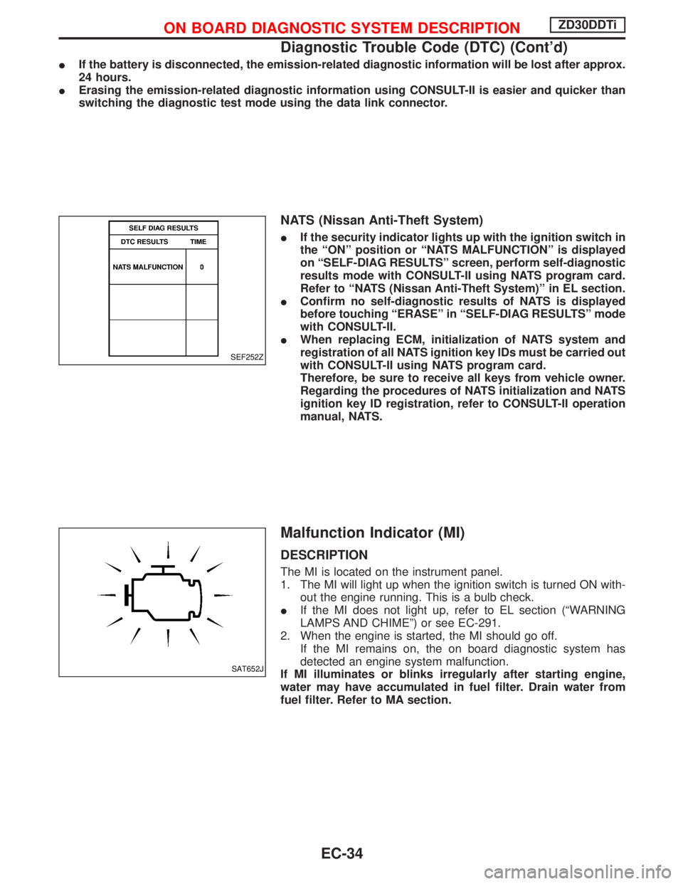
NATS (Nissan Anti-Theft System)
IIf the security indicator lights up with the ignition switch in
the ªONº position or ªNATS MALFUNCTIONº is displayed
on ªSELF-DIAG RESULTSº screen, perform self-diagnostic
results mode with CONSULT-II using NATS program card.
Refer to ªNATS (Nissan Anti-Theft System)º in EL section.
IConfirm no self-diagnostic results of NATS is displayed
before touching ªERASEº in ªSELF-DIAG RESULTSº mode
with CONSULT-II.
IWhen replacing ECM, initialization of NATS system and
registration of all NATS ignition key IDs must be carried out
with CONSULT-II using NATS program card.
Therefore, be sure to receive all keys from vehicle owner.
Regarding the procedures of NATS initialization and NATS
ignition key ID registration, refer to CONSULT-II operation
manual, NATS.
Malfunction Indicator (MI)
DESCRIPTION
The MI is located on the instrument panel.
1. The MI will light up when the ignition switch is turned ON with-
out the engine running. This is a bulb check.
IIf the MI does not light up, refer to EL section (ªWARNING
LAMPS AND CHIMEº) or see EC-291.
2. When the engine is started, the MI should go off.
If the MI remains on, the on board diagnostic system has
detected an engine system malfunction.
If MI illuminates or blinks irregularly after starting engine,
water may have accumulated in fuel filter. Drain water from
fuel filter. Refer to MA section.
SEF252Z
SAT652J
ON BOARD DIAGNOSTIC SYSTEM DESCRIPTIONZD30DDTi
Diagnostic Trouble Code (DTC) (Cont'd)
EC-34
Page 698 of 1767
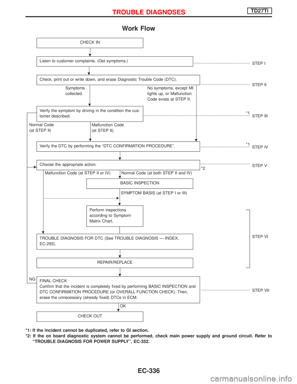
Work Flow
CHECK IN
Listen to customer complaints. (Get symptoms.).................................................
STEP I
Check, print out or write down, and erase Diagnostic Trouble Code (DTC).
...........................................
STEP II
Symptoms
collected.No symptoms, except MI
lights up, or Malfunction
Code exists at STEP II.
Verify the symptom by driving in the condition the cus-
tomer described.
H
*1
.............................................................................................
STEP III
Normal Code
(at STEP II)
Malfunction Code
(at STEP II)
Verify the DTC by performing the ªDTC CONFIRMATION PROCEDUREº.
*1
...........................................
STEP IV
EChoose the appropriate action.
Malfunction Code (at STEP II or IV) Normal Code (at both STEP II and IV)...........................................
*2STEP V
BASIC INSPECTION
SYMPTOM BASIS (at STEP I or III)
................................................................
E
Perform inspections
according to Symptom
Matrix Chart.
TROUBLE DIAGNOSIS FOR DTC (See TROUBLE DIAGNOSIS Ð INDEX,
EC-293).STEP VI
REPAIR/REPLACE
NGFINAL CHECK
Confirm that the incident is completely fixed by performing BASIC INSPECTION and
DTC CONFIRMATION PROCEDURE (or OVERALL FUNCTION CHECK). Then,
erase the unnecessary (already fixed) DTCs in ECM.
OK...........................................
STEP VII
CHECK OUT
*1: If the incident cannot be duplicated, refer to GI section.
*2: If the on board diagnostic system cannot be performed, check main power supply and ground circuit. Refer to
ªTROUBLE DIAGNOSIS FOR POWER SUPPLYº, EC-352.
H
H
H
H
H
H
H
H
H
H
H
TROUBLE DIAGNOSESTD27Ti
EC-336
Page 1002 of 1767
System Description
NATS has the following immobiliser functions:
IThis version of NATS has dongle control unit to improve its anti-theft performance (RHD models). Dongle
control unit has its own ID which is registered into NATS IMMU. So if dongle unit is replaced, initialization
must be carried out.
IWhen malfunction of dongle unit is detected:
The security indicator lamp illuminates for about 15 minutes after ignition switch is turned to ON.
Ð When dongle control unit has a malfunction, and the indicator lamp is illuminated, engine can not be
started. However engine can be started only one time when security indicator lamp turns off in about
15 minutes after ignition switch is turned to ON.
ISince only NATS ignition keys, whose ID nos. have been registered into the ECM and IMMU of NATS,
allow the engine to run, operation of a stolen vehicle without a NATS registered key is prevented by NATS.
That is to say, NATS will immobilize the engine if someone tries to start it without the registered key of
NATS.
IAll of the originally supplied ignition key IDs have been NATS registered.
If requested by the vehicle owner, a maximum of five key IDs can be registered into the NATS compo-
nents.
IThe NATS security indicator (NATS security ind.) blinks when the ignition switch is in ªOFFº or ªACCº
position. Therefore, NATS warns outsiders that the vehicle is equipped with the anti-theft system.
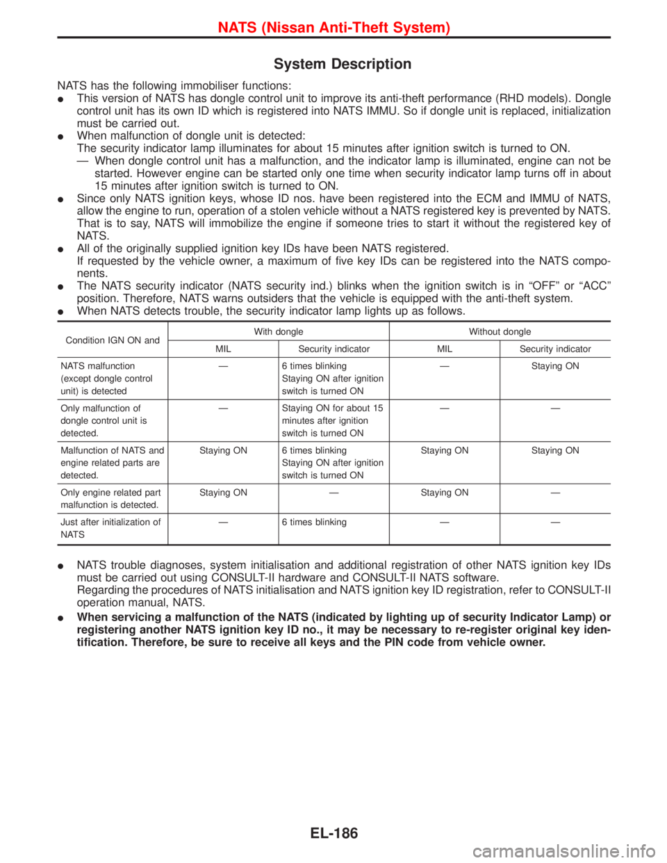
IWhen NATS detects trouble, the security indicator lamp lights up as follows.
Condition IGN ON andWith dongle Without dongle
MIL Security indicator MIL Security indicator
NATS malfunction
(except dongle control
unit) is detectedÐ 6 times blinking
Staying ON after ignition
switch is turned ONÐ Staying ON
Only malfunction of
dongle control unit is
detected.Ð Staying ON for about 15
minutes after ignition
switch is turned ONÐÐ
Malfunction of NATS and
engine related parts are
detected.Staying ON 6 times blinking
Staying ON after ignition
switch is turned ONStaying ON Staying ON
Only engine related part
malfunction is detected.Staying ON Ð Staying ON Ð
Just after initialization of
NATSÐ 6 times blinking Ð Ð
INATS trouble diagnoses, system initialisation and additional registration of other NATS ignition key IDs
must be carried out using CONSULT-II hardware and CONSULT-II NATS software.
Regarding the procedures of NATS initialisation and NATS ignition key ID registration, refer to CONSULT-II
operation manual, NATS.
IWhen servicing a malfunction of the NATS (indicated by lighting up of security Indicator Lamp) or
registering another NATS ignition key ID no., it may be necessary to re-register original key iden-
tification. Therefore, be sure to receive all keys and the PIN code from vehicle owner.
NATS (Nissan Anti-Theft System)
EL-186
Page 1012 of 1767
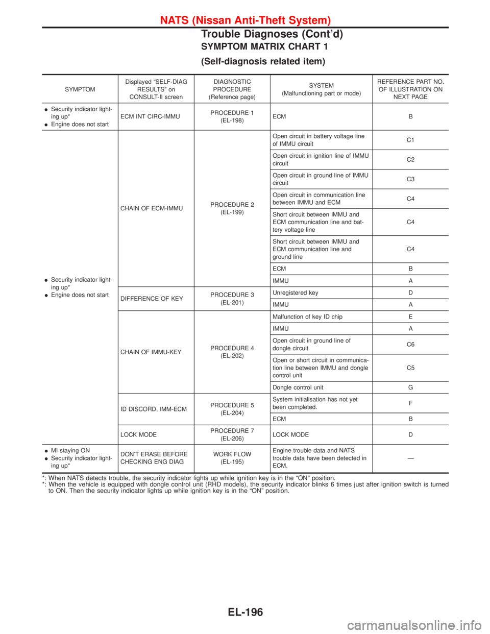
SYMPTOM MATRIX CHART 1
(Self-diagnosis related item)
SYMPTOMDisplayed ªSELF-DIAG
RESULTSº on
CONSULT-II screenDIAGNOSTIC
PROCEDURE
(Reference page)SYSTEM
(Malfunctioning part or mode)REFERENCE PART NO.
OF ILLUSTRATION ON
NEXT PAGE
ISecurity indicator light-
ing up*
IEngine does not startECM INT CIRC-IMMUPROCEDURE 1
(EL-198)ECM B
ISecurity indicator light-
ing up*
IEngine does not startCHAIN OF ECM-IMMUPROCEDURE 2
(EL-199)Open circuit in battery voltage line
of IMMU circuitC1
Open circuit in ignition line of IMMU
circuitC2
Open circuit in ground line of IMMU
circuitC3
Open circuit in communication line
between IMMU and ECMC4
Short circuit between IMMU and
ECM communication line and bat-
tery voltage lineC4
Short circuit between IMMU and
ECM communication line and
ground lineC4
ECM B
IMMU A
DIFFERENCE OF KEYPROCEDURE 3
(EL-201)Unregistered key D
IMMU A
CHAIN OF IMMU-KEYPROCEDURE 4
(EL-202)Malfunction of key ID chip E
IMMU A
Open circuit in ground line of
dongle circuitC6
Open or short circuit in communica-
tion line between IMMU and dongle
control unitC5
Dongle control unit G
ID DISCORD, IMM-ECMPROCEDURE 5
(EL-204)System initialisation has not yet
been completed.F
ECM B
LOCK MODEPROCEDURE 7
(EL-206)LOCK MODE D
IMI staying ON
ISecurity indicator light-
ing up*DON'T ERASE BEFORE
CHECKING ENG DIAGWORK FLOW
(EL-195)Engine trouble data and NATS
trouble data have been detected in
ECM.Ð
*: When NATS detects trouble, the security indicator lights up while ignition key is in the ªONº position.
*: When the vehicle is equipped with dongle control unit (RHD models), the security indicator blinks 6 times just after ignition switch is turned
to ON. Then the security indicator lights up while ignition key is in the ªONº position.
NATS (Nissan Anti-Theft System)
Trouble Diagnoses (Cont'd)
EL-196
Page 1462 of 1767
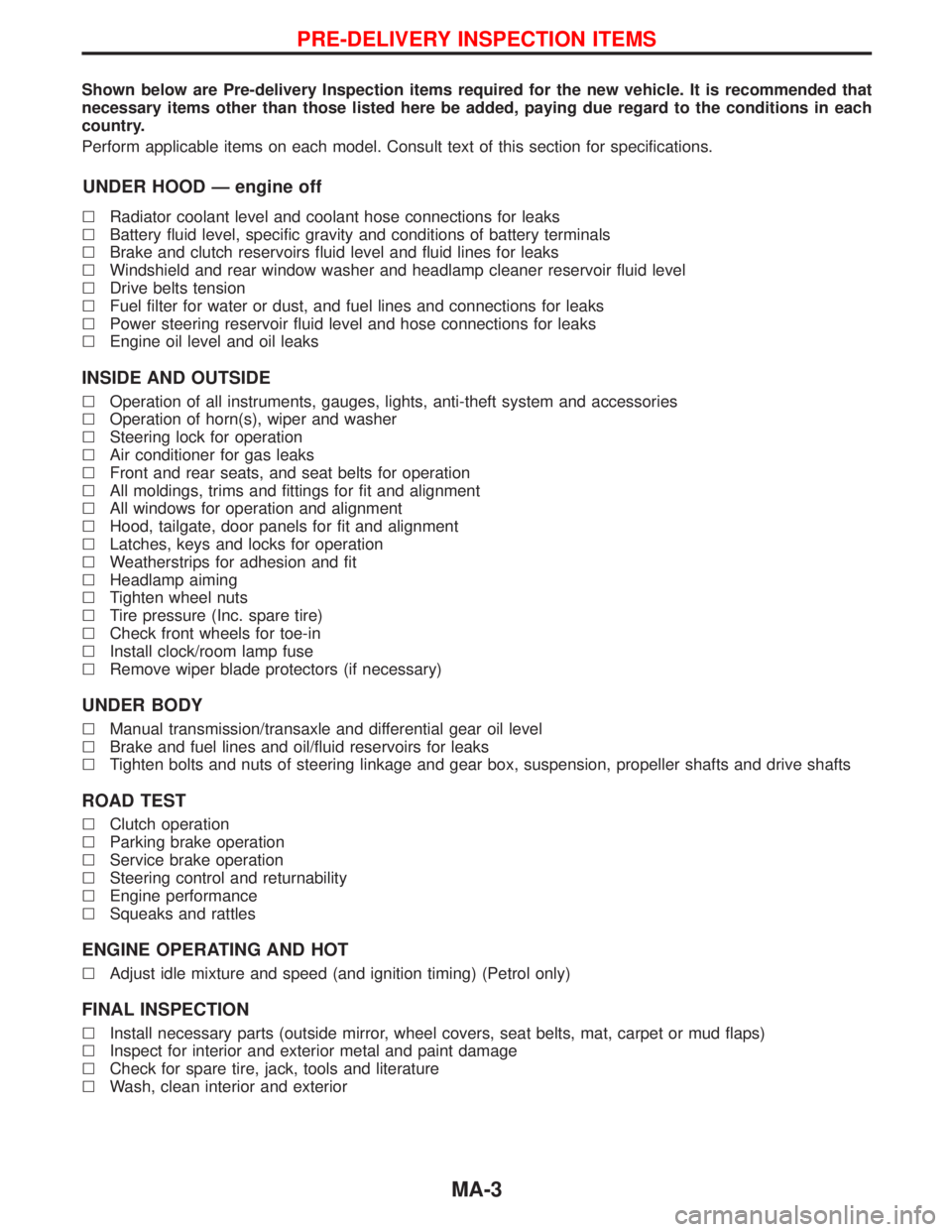
Shown below are Pre-delivery Inspection items required for the new vehicle. It is recommended that
necessary items other than those listed here be added, paying due regard to the conditions in each
country.
Perform applicable items on each model. Consult text of this section for specifications.
UNDER HOOD Ð engine off
lRadiator coolant level and coolant hose connections for leaks
lBattery fluid level, specific gravity and conditions of battery terminals
lBrake and clutch reservoirs fluid level and fluid lines for leaks
lWindshield and rear window washer and headlamp cleaner reservoir fluid level
lDrive belts tension
lFuel filter for water or dust, and fuel lines and connections for leaks
lPower steering reservoir fluid level and hose connections for leaks
lEngine oil level and oil leaks
INSIDE AND OUTSIDE
lOperation of all instruments, gauges, lights, anti-theft system and accessories
lOperation of horn(s), wiper and washer
lSteering lock for operation
lAir conditioner for gas leaks
lFront and rear seats, and seat belts for operation
lAll moldings, trims and fittings for fit and alignment
lAll windows for operation and alignment
lHood, tailgate, door panels for fit and alignment
lLatches, keys and locks for operation
lWeatherstrips for adhesion and fit
lHeadlamp aiming
lTighten wheel nuts
lTire pressure (Inc. spare tire)
lCheck front wheels for toe-in
lInstall clock/room lamp fuse
lRemove wiper blade protectors (if necessary)
UNDER BODY
lManual transmission/transaxle and differential gear oil level
lBrake and fuel lines and oil/fluid reservoirs for leaks
lTighten bolts and nuts of steering linkage and gear box, suspension, propeller shafts and drive shafts
ROAD TEST
lClutch operation
lParking brake operation
lService brake operation
lSteering control and returnability
lEngine performance
lSqueaks and rattles
ENGINE OPERATING AND HOT
lAdjust idle mixture and speed (and ignition timing) (Petrol only)
FINAL INSPECTION
lInstall necessary parts (outside mirror, wheel covers, seat belts, mat, carpet or mud flaps)
lInspect for interior and exterior metal and paint damage
lCheck for spare tire, jack, tools and literature
lWash, clean interior and exterior
PRE-DELIVERY INSPECTION ITEMS
MA-3
Page 1463 of 1767
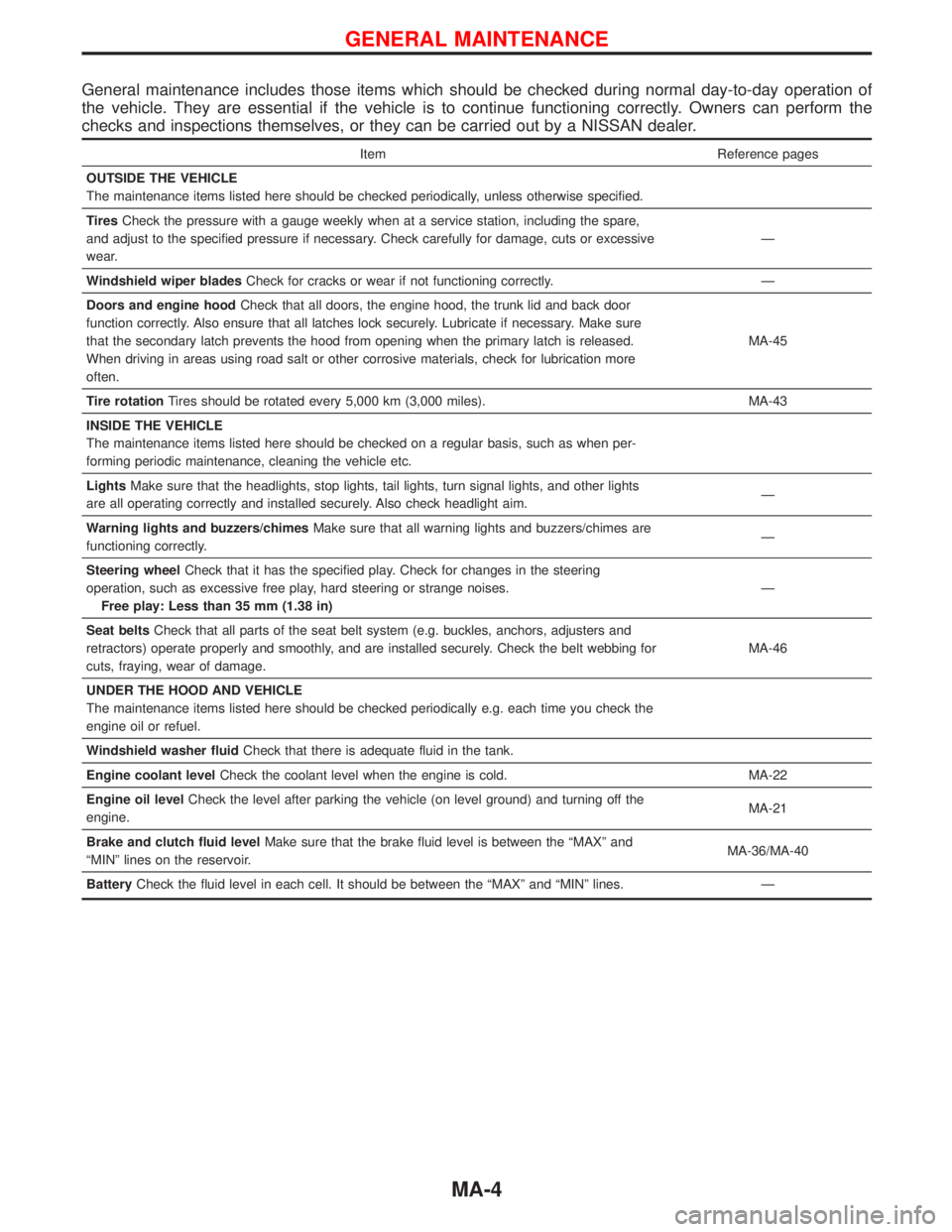
General maintenance includes those items which should be checked during normal day-to-day operation of
the vehicle. They are essential if the vehicle is to continue functioning correctly. Owners can perform the
checks and inspections themselves, or they can be carried out by a NISSAN dealer.
Item Reference pages
OUTSIDE THE VEHICLE
The maintenance items listed here should be checked periodically, unless otherwise specified.
TiresCheck the pressure with a gauge weekly when at a service station, including the spare,
and adjust to the specified pressure if necessary. Check carefully for damage, cuts or excessive
wear.Ð
Windshield wiper bladesCheck for cracks or wear if not functioning correctly. Ð
Doors and engine hoodCheck that all doors, the engine hood, the trunk lid and back door
function correctly. Also ensure that all latches lock securely. Lubricate if necessary. Make sure
that the secondary latch prevents the hood from opening when the primary latch is released.
When driving in areas using road salt or other corrosive materials, check for lubrication more
often.MA-45
Tire rotationTires should be rotated every 5,000 km (3,000 miles). MA-43
INSIDE THE VEHICLE
The maintenance items listed here should be checked on a regular basis, such as when per-
forming periodic maintenance, cleaning the vehicle etc.
LightsMake sure that the headlights, stop lights, tail lights, turn signal lights, and other lights
are all operating correctly and installed securely. Also check headlight aim.Ð
Warning lights and buzzers/chimesMake sure that all warning lights and buzzers/chimes are
functioning correctly.Ð
Steering wheelCheck that it has the specified play. Check for changes in the steering
operation, such as excessive free play, hard steering or strange noises.
Free play: Less than 35 mm (1.38 in)Ð
Seat beltsCheck that all parts of the seat belt system (e.g. buckles, anchors, adjusters and
retractors) operate properly and smoothly, and are installed securely. Check the belt webbing for
cuts, fraying, wear of damage.MA-46
UNDER THE HOOD AND VEHICLE
The maintenance items listed here should be checked periodically e.g. each time you check the
engine oil or refuel.
Windshield washer fluidCheck that there is adequate fluid in the tank.
Engine coolant levelCheck the coolant level when the engine is cold. MA-22
Engine oil levelCheck the level after parking the vehicle (on level ground) and turning off the
engine.MA-21
Brake and clutch fluid levelMake sure that the brake fluid level is between the ªMAXº and
ªMINº lines on the reservoir.MA-36/MA-40
BatteryCheck the fluid level in each cell. It should be between the ªMAXº and ªMINº lines. Ð
GENERAL MAINTENANCE
MA-4
Page 1485 of 1767
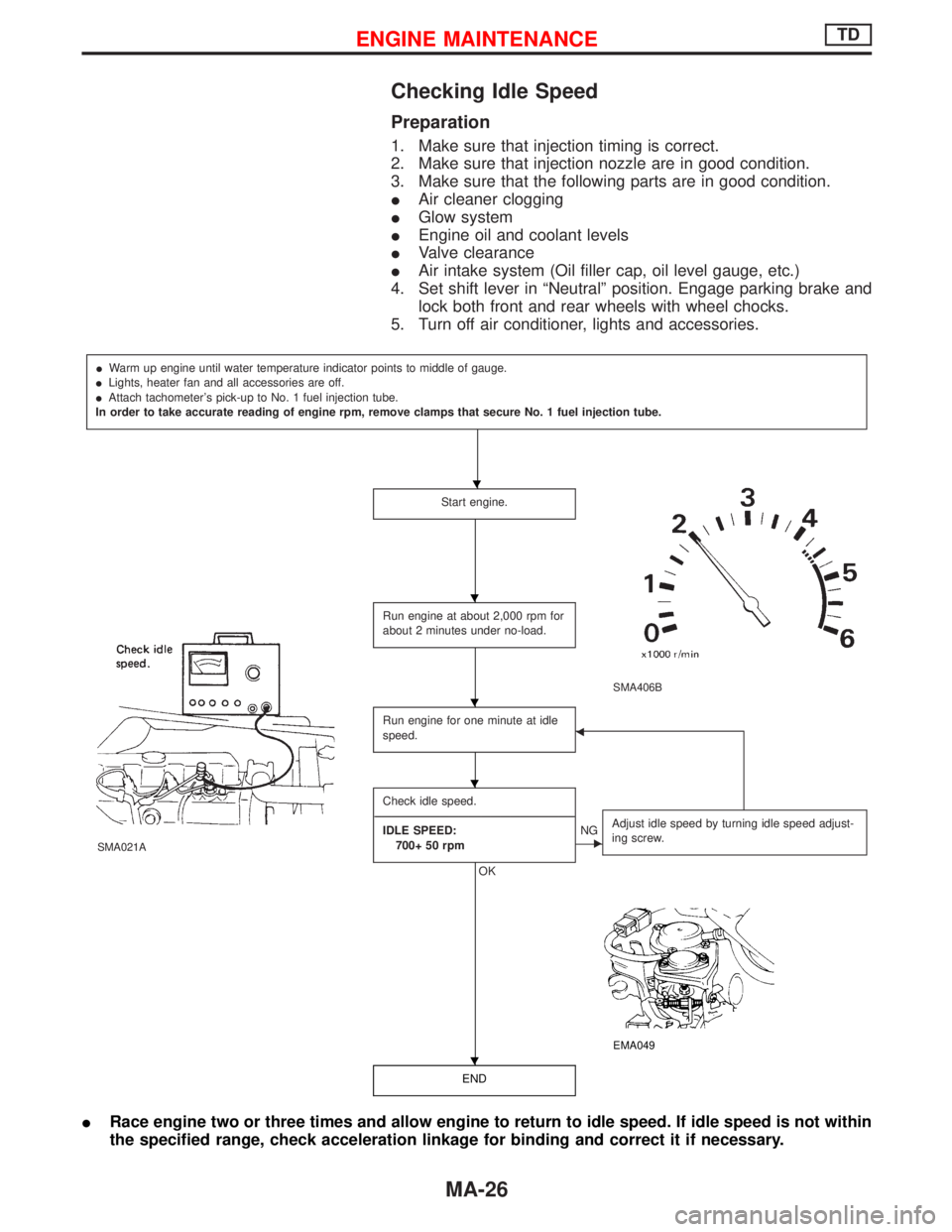
Checking Idle Speed
Preparation
1. Make sure that injection timing is correct.
2. Make sure that injection nozzle are in good condition.
3. Make sure that the following parts are in good condition.
IAir cleaner clogging
IGlow system
IEngine oil and coolant levels
IValve clearance
IAir intake system (Oil filler cap, oil level gauge, etc.)
4. Set shift lever in ªNeutralº position. Engage parking brake and
lock both front and rear wheels with wheel chocks.
5. Turn off air conditioner, lights and accessories.
IWarm up engine until water temperature indicator points to middle of gauge.
ILights, heater fan and all accessories are off.
IAttach tachometer's pick-up to No. 1 fuel injection tube.
In order to take accurate reading of engine rpm, remove clamps that secure No. 1 fuel injection tube.
Start engine.
SMA406B
SMA021A
Run engine at about 2,000 rpm for
about 2 minutes under no-load.
Run engine for one minute at idle
speed.F
Check idle speed.
----------------------------------------------------------------------------------------------------------------------------------------------------------------------------------------------------------------------------------
IDLE SPEED:
700+ 50 rpm
OK
ENGAdjust idle speed by turning idle speed adjust-
ing screw.
EMA049
END
IRace engine two or three times and allow engine to return to idle speed. If idle speed is not within
the specified range, check acceleration linkage for binding and correct it if necessary.
H
H
H
H
H
ENGINE MAINTENANCETD
MA-26
Page 1648 of 1767
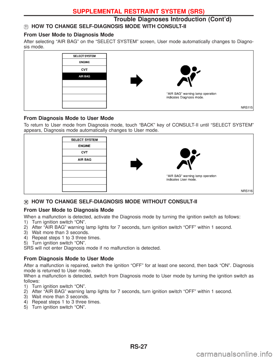
HOW TO CHANGE SELF-DIAGNOSIS MODE WITH CONSULT-II
From User Mode to Diagnosis Mode
After selecting ªAIR BAGº on the ªSELECT SYSTEMº screen, User mode automatically changes to Diagno-
sis mode.
From Diagnosis Mode to User Mode
To return to User mode from Diagnosis mode, touch ªBACKº key of CONSULT-II until ªSELECT SYSTEMº
appears, Diagnosis mode automatically changes to User mode.
HOW TO CHANGE SELF-DIAGNOSIS MODE WITHOUT CONSULT-II
From User Mode to Diagnosis Mode
When a malfunction is detected, activate the Diagnosis mode by turning the ignition switch as follows:
1) Turn ignition switch ªONº.
2) After ªAIR BAGº warning lamp lights for 7 seconds, turn ignition switch ªOFFº within 1 second.
3) Wait more than 3 seconds.
4) Repeat steps 1 to 3 three times.
5) Turn ignition switch ªONº.
SRS will not enter Diagnosis mode if no malfunction is detected.
From Diagnosis Mode to User Mode
After a malfunction is repaired, switch the ignition ªOFFº for at least one second, then back ªONº. Diagnosis
mode is returned to User mode.
When a malfunction is detected, switch from Diagnosis mode to User mode by turning the ignition switch as
follows:
1) Turn ignition switch ªONº.
2) After ªAIR BAGº warning lamp lights for 7 seconds, turn ignition switch ªOFFº within 1 second.
3) Wait more than 3 seconds.
4) Repeat steps 1 to 3 three times.
5) Turn ignition switch ªONº.
NRS115
NRS116
SUPPLEMENTAL RESTRAINT SYSTEM (SRS)
Trouble Diagnoses Introduction (Cont'd)
RS-27
Page 1667 of 1767
![NISSAN TERRANO 2002 Service Repair Manual Diagnostic item Explanation Repair order
PRE-TEN FRONT RH
[OPEN/VB-SHORT]IThe circuit for front RH seat belt pre-
tensioner is open or shorted to a power
supply circuit.1. Visually check the wiring ha NISSAN TERRANO 2002 Service Repair Manual Diagnostic item Explanation Repair order
PRE-TEN FRONT RH
[OPEN/VB-SHORT]IThe circuit for front RH seat belt pre-
tensioner is open or shorted to a power
supply circuit.1. Visually check the wiring ha](/img/5/57393/w960_57393-1666.png)
Diagnostic item Explanation Repair order
PRE-TEN FRONT RH
[OPEN/VB-SHORT]IThe circuit for front RH seat belt pre-
tensioner is open or shorted to a power
supply circuit.1. Visually check the wiring harness con-
nections.
2. Replace the harness if it has visible
damage.
3. If the harness check is OK, replace the
diagnosis sensor unit and front RH seat
belt. (Before disposing of the front RH
seat belt pre-tensioner, if must be
deployed.) PRE-TEN FRONT RH
[GND-SHORT]IThe circuit for front RH seat belt pre-
tensioner is shorted to ground.
CONTROL UNITIDiagnosis sensor unit is malfunctioning. 1. Visually check the wiring harness con-
nection.
2. Replace the harness if it has visible
damage.
3. If the harness check is OK, replace the
diagnosis sensor unit.
* Follow the procedures in numerical order when repairing malfunctioning parts, then make the final system check.
Trouble Diagnoses without CONSULT-II
DIAGNOSTIC PROCEDURE 6
Inspecting SRS malfunctioning parts by using ªAIR BAGº
warning lamp Ð Diagnosis mode
NOTE:
SRS will not enter Diagnosis mode if no malfunction is
detected in User mode.
1. Turn ignition switch ªONº.
2. After ªAIR BAGº warning lamp lights for 7 seconds, turn ignition
switch ªOFFº within 1 second.
3. Wait more than 3 seconds.
4. Repeat steps 1 to 3 three times.
5. Turn ignition switch ªONº.
SRS is now in Diagnosis mode.
6. ªAIR BAGº warning lamp operates in Diagnosis mode as fol-
lows:
NOTE:
If SRS does not enter Diagnosis mode even though malfunc-
tion is detected in User mode, check the battery voltage.
If the battery voltage is less than 9V, charge the battery. Then
go to DIAGNOSTIC PROCEDURE 7, page RS-51.
If the battery voltage is OK, replace the diagnosis sensor unit.
SRS800
SUPPLEMENTAL RESTRAINT SYSTEM (SRS)
Trouble Diagnoses with CONSULT-II (Cont'd)
RS-46