open hood NISSAN TERRANO 2002 Service Repair Manual
[x] Cancel search | Manufacturer: NISSAN, Model Year: 2002, Model line: TERRANO, Model: NISSAN TERRANO 2002Pages: 1767, PDF Size: 41.51 MB
Page 293 of 1767
Checking Body Corrosion
Visually check the body sheet metal panel for corrosion, paint damage (scratches, chipping, rubbing, etc.) or
damage to the anti-corrosion materials. In particular, check the following locations.
Hemmed portion
Hood front end, door lower end, back door rear end, etc.
Panel joint
Side sill of rear fender and center pillar, rear wheel housing of rear fender, around strut tower in engine
compartment, etc.
Panel edge
Back door opening, sunroof opening, fender wheelarch flange, fuel filler lid flange, around holes in panel, etc.
Parts contact
Waist molding, windshield molding, bumper, etc.
Protectors
Damage or condition of mudguard, fender protector, chipping protector, etc.
Anti-corrosion materials
Damage or separation of anti-corrosion materials under the body.
Drain holes
Condition of drain holes at door and side sill.
When repairing corroded areas, refer to the Corrosion Repair Manual.
CHASSIS AND BODY MAINTENANCE
BT-5
Page 294 of 1767

Removal and Installation
IWhen removing or installing hood, place a cloth or other padding on hood. This prevents vehicle body from
being scratched.
IBumper fascia is made of plastic. Do not use excessive force and be sure to keep oil away from it.
IHood adjustment: Adjust at hinge portion.
IHood lock adjustment: After adjusting, check hood lock control operation. Apply a coat of grease to hood
locks engaging mechanism.
IHood opener: Do not attempt to bend cable forcibly. Doing so increases effort required to unlock hood.
BODY FRONT END
BT-6
Page 412 of 1767
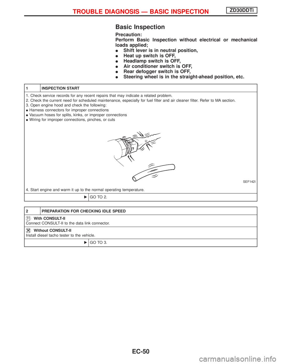
Basic Inspection
Precaution:
Perform Basic Inspection without electrical or mechanical
loads applied;
IShift lever is in neutral position,
IHeat up switch is OFF,
IHeadlamp switch is OFF,
IAir conditioner switch is OFF,
IRear defogger switch is OFF,
ISteering wheel is in the straight-ahead position, etc.
1 INSPECTION START
1. Check service records for any recent repairs that may indicate a related problem.
2. Check the current need for scheduled maintenance, especially for fuel filter and air cleaner filter. Refer to MA section.
3. Open engine hood and check the following:
IHarness connectors for improper connections
IVacuum hoses for splits, kinks, or improper connections
IWiring for improper connections, pinches, or cuts
SEF142I
4. Start engine and warm it up to the normal operating temperature.
EGO TO 2.
2 PREPARATION FOR CHECKING IDLE SPEED
With CONSULT-II
Connect CONSULT-II to the data link connector.
Without CONSULT-II
Install diesel tacho tester to the vehicle.
EGO TO 3.
TROUBLE DIAGNOSIS Ð BASIC INSPECTIONZD30DDTi
EC-50
Page 700 of 1767
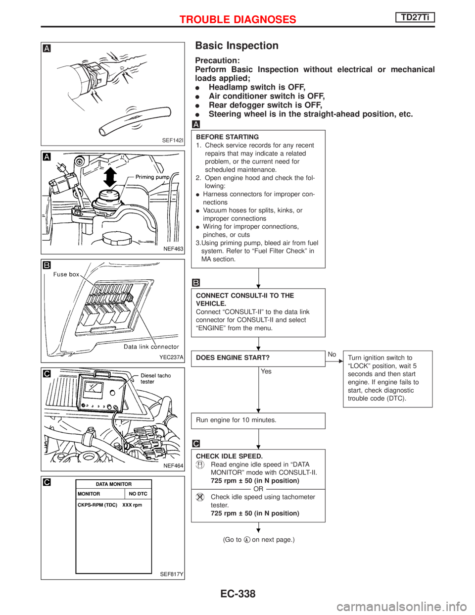
Basic Inspection
Precaution:
Perform Basic Inspection without electrical or mechanical
loads applied;
IHeadlamp switch is OFF,
IAir conditioner switch is OFF,
IRear defogger switch is OFF,
ISteering wheel is in the straight-ahead position, etc.
BEFORE STARTING
1. Check service records for any recent
repairs that may indicate a related
problem, or the current need for
scheduled maintenance.
2. Open engine hood and check the fol-
lowing:
IHarness connectors for improper con-
nections
IVacuum hoses for splits, kinks, or
improper connections
IWiring for improper connections,
pinches, or cuts
3.Using priming pump, bleed air from fuel
system. Refer to ªFuel Filter Checkº in
MA section.
CONNECT CONSULT-II TO THE
VEHICLE.
Connect ªCONSULT-IIº to the data link
connector for CONSULT-II and select
ªENGINEº from the menu.
DOES ENGINE START?
Ye s
ENo
Turn ignition switch to
ªLOCKº position, wait 5
seconds and then start
engine. If engine fails to
start, check diagnostic
trouble code (DTC).
Run engine for 10 minutes.
CHECK IDLE SPEED.
Read engine idle speed in ªDATA
MONITORº mode with CONSULT-II.
725 rpm 50 (in N position)
------------------------------------------------------------------------------------------------------------------------------------OR------------------------------------------------------------------------------------------------------------------------------------
Check idle speed using tachometer
tester.
725 rpm 50 (in N position)
(Go toqAon next page.)
SEF142I
NEF463
YEC237A
NEF464
SEF817Y
H
H
H
H
H
TROUBLE DIAGNOSESTD27Ti
EC-338
Page 997 of 1767
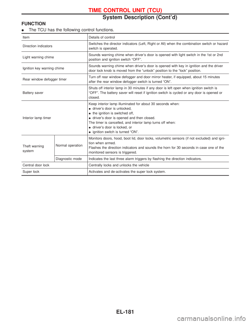
FUNCTION
IThe TCU has the following control functions.
Item Details of control
Direction indicatorsSwitches the director indicators (Left, Right or All) when the combination switch or hazard
switch is operated.
Light warning chimeSounds warning chime when driver's door is opened with light switch in the 1st or 2nd
position and ignition switch ªOFFº.
Ignition key warning chimeSounds warning chime when driver's door is opened with key in ignition and the driver
door lock knob is moved from the ªunlockº position to the ªlockº position.
Rear window defogger timerTurn off rear window defogger and door mirror heater, if equipped, about 15 minutes
after the rear window defogger switch is turned ªONº.
Battery saverShuts off interior lamp in 30 minutes if any door is left open when ignition switch is
ªOFFº. The battery saver will reset if ignition switch is cycled or any door is opened or
closed.
Interior lamp timerKeep interior lamp illuminated for about 30 seconds when:
Idriver's door is unlocked,
Ithe ignition is switched off,
Idriver's door is opened and then closed.
The timer is cancelled, and interior lamp turns off when:
Idriver's door is locked, or
Iignition switch is turned ªONº.
Theft warning
systemNormal operationMonitors doors, hood, boot lid, door locks, volumetric sensors (if not excluded) and igni-
tion when armed.
Flashes the direction indicators and sounds the horn for 30 seconds in case one of the
monitored sensors is triggered.
Diagnostic mode Indicates the last three alarm triggers by flashing the direction indicators.
Central door lock Centrally locks and unlocks the vehicle
Super lock Activates and de-activates the super lock system.
TIME CONTROL UNIT (TCU)
System Description (Cont'd)
EL-181
Page 999 of 1767
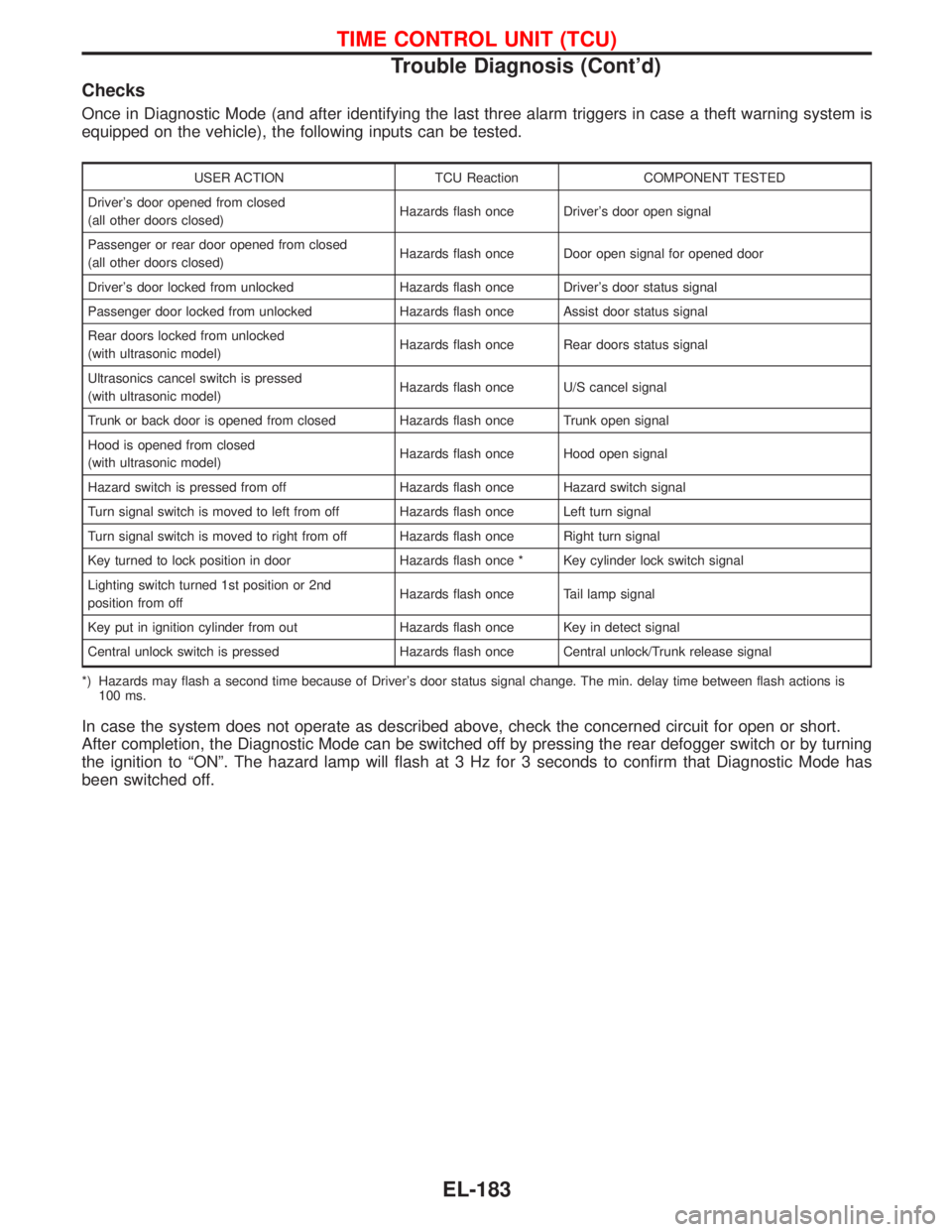
Checks
Once in Diagnostic Mode (and after identifying the last three alarm triggers in case a theft warning system is
equipped on the vehicle), the following inputs can be tested.
USER ACTION TCU Reaction COMPONENT TESTED
Driver's door opened from closed
(all other doors closed)Hazards flash once Driver's door open signal
Passenger or rear door opened from closed
(all other doors closed)Hazards flash once Door open signal for opened door
Driver's door locked from unlocked Hazards flash once Driver's door status signal
Passenger door locked from unlocked Hazards flash once Assist door status signal
Rear doors locked from unlocked
(with ultrasonic model)Hazards flash once Rear doors status signal
Ultrasonics cancel switch is pressed
(with ultrasonic model)Hazards flash once U/S cancel signal
Trunk or back door is opened from closed Hazards flash once Trunk open signal
Hood is opened from closed
(with ultrasonic model)Hazards flash once Hood open signal
Hazard switch is pressed from off Hazards flash once Hazard switch signal
Turn signal switch is moved to left from off Hazards flash once Left turn signal
Turn signal switch is moved to right from off Hazards flash once Right turn signal
Key turned to lock position in door Hazards flash once * Key cylinder lock switch signal
Lighting switch turned 1st position or 2nd
position from offHazards flash once Tail lamp signal
Key put in ignition cylinder from out Hazards flash once Key in detect signal
Central unlock switch is pressed Hazards flash once Central unlock/Trunk release signal
*) Hazards may flash a second time because of Driver's door status signal change. The min. delay time between flash actions is
100 ms.
In case the system does not operate as described above, check the concerned circuit for open or short.
After completion, the Diagnostic Mode can be switched off by pressing the rear defogger switch or by turning
the ignition to ªONº. The hazard lamp will flash at 3 Hz for 3 seconds to confirm that Diagnostic Mode has
been switched off.
TIME CONTROL UNIT (TCU)
Trouble Diagnosis (Cont'd)
EL-183
Page 1027 of 1767
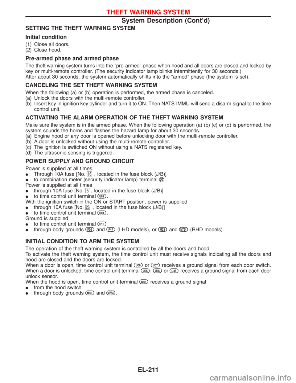
SETTING THE THEFT WARNING SYSTEM
Initial condition
(1) Close all doors.
(2) Close hood.
Pre-armed phase and armed phase
The theft warning system turns into the ªpre-armedº phase when hood and all doors are closed and locked by
key or multi-remote controller. (The security indicator lamp blinks intermittently for 30 seconds.)
After about 30 seconds, the system automatically shifts into the ªarmedº phase (the system is set).
CANCELING THE SET THEFT WARNING SYSTEM
When the following (a) or (b) operation is performed, the armed phase is canceled.
(a) Unlock the doors with the multi-remote controller.
(b) Insert key in ignition key cylinder and turn it to ON. Then NATS IMMU will send a disarm signal to the time
control unit.
ACTIVATING THE ALARM OPERATION OF THE THEFT WARNING SYSTEM
Make sure the system is in the armed phase. When the following operation (a) (b) (c) or (d) is performed, the
system sounds the horns and flashes the hazard lamp for about 30 seconds.
(a) Engine hood or any door is opened before unlocking door with the multi-remote controller.
(b) A door is unlocked without using the multi-remote controller.
(c) The ignition is switched ON without using a NATS registered key.
(d) The ultrasonic sensing is triggered.
POWER SUPPLY AND GROUND CIRCUIT
Power is supplied at all times.
IThrough 10A fuse [No.
16, located in the fuse block (J/B)]
Ito combination meter (security indicator lamp) terminalq
27.
Power is supplied at all times
Ithrough 10A fuse [No.
5, located in the fuse block (J/B)]
Ito time control unit terminal
U09.
With the ignition switch in the ON or START position, power is supplied
Ithrough 10A fuse [No.
26, located in the fuse block (J/B)]
Ito time control unit terminal
U01.
Ground is supplied
Ito time control unit terminal
U16
Ithrough body groundsF36andF47(LHD models), orM33andM754(RHD models).
INITIAL CONDITION TO ARM THE SYSTEM
The operation of the theft warning system is controlled by all the doors and hood.
To activate the theft warning system, the time control unit must receive signals indicating all the doors and
hood are closed and the doors are locked.
When a door is open, time control unit terminal
U06orU07receives a ground signal from each door switch.
When a door is unlocked, time control unit terminal
U25,U35orU36receives a ground signal from each door
unlock sensor.
When the hood is open, time control unit terminal
U32receives a ground signal
Ifrom the hood switch
Ithrough body grounds
M33andM754.
THEFT WARNING SYSTEM
System Description (Cont'd)
EL-211
Page 1028 of 1767
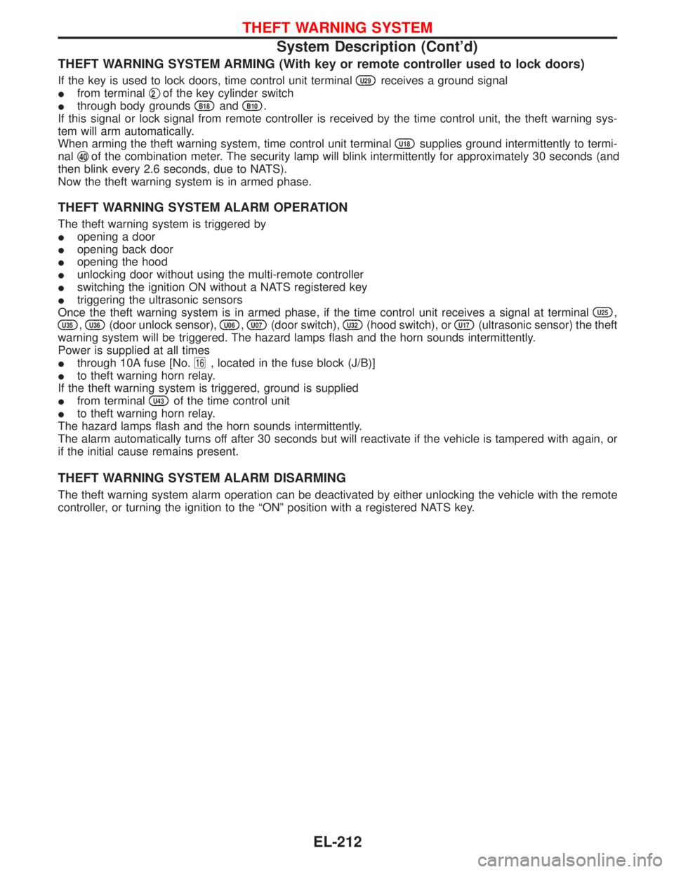
THEFT WARNING SYSTEM ARMING (With key or remote controller used to lock doors)
If the key is used to lock doors, time control unit terminalU29receives a ground signal
Ifrom terminalq
2of the key cylinder switch
Ithrough body grounds
B18andB10.
If this signal or lock signal from remote controller is received by the time control unit, the theft warning sys-
tem will arm automatically.
When arming the theft warning system, time control unit terminal
U18supplies ground intermittently to termi-
nalq
40of the combination meter. The security lamp will blink intermittently for approximately 30 seconds (and
then blink every 2.6 seconds, due to NATS).
Now the theft warning system is in armed phase.
THEFT WARNING SYSTEM ALARM OPERATION
The theft warning system is triggered by
Iopening a door
Iopening back door
Iopening the hood
Iunlocking door without using the multi-remote controller
Iswitching the ignition ON without a NATS registered key
Itriggering the ultrasonic sensors
Once the theft warning system is in armed phase, if the time control unit receives a signal at terminal
U25,
U35,U36(door unlock sensor),U06,U07(door switch),U32(hood switch), orU17(ultrasonic sensor) the theft
warning system will be triggered. The hazard lamps flash and the horn sounds intermittently.
Power is supplied at all times
Ithrough 10A fuse [No.
16, located in the fuse block (J/B)]
Ito theft warning horn relay.
If the theft warning system is triggered, ground is supplied
Ifrom terminal
U43of the time control unit
Ito theft warning horn relay.
The hazard lamps flash and the horn sounds intermittently.
The alarm automatically turns off after 30 seconds but will reactivate if the vehicle is tampered with again, or
if the initial cause remains present.
THEFT WARNING SYSTEM ALARM DISARMING
The theft warning system alarm operation can be deactivated by either unlocking the vehicle with the remote
controller, or turning the ignition to the ªONº position with a registered NATS key.
THEFT WARNING SYSTEM
System Description (Cont'd)
EL-212
Page 1046 of 1767
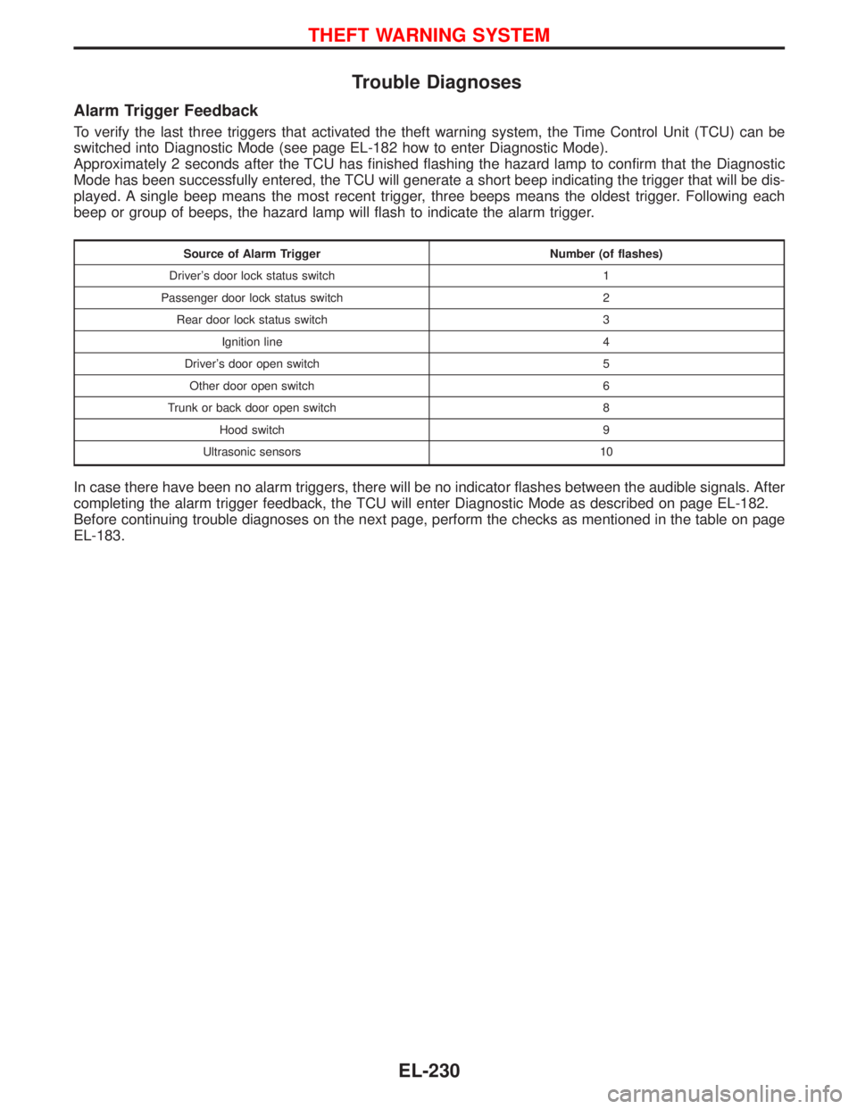
Trouble Diagnoses
Alarm Trigger Feedback
To verify the last three triggers that activated the theft warning system, the Time Control Unit (TCU) can be
switched into Diagnostic Mode (see page EL-182 how to enter Diagnostic Mode).
Approximately 2 seconds after the TCU has finished flashing the hazard lamp to confirm that the Diagnostic
Mode has been successfully entered, the TCU will generate a short beep indicating the trigger that will be dis-
played. A single beep means the most recent trigger, three beeps means the oldest trigger. Following each
beep or group of beeps, the hazard lamp will flash to indicate the alarm trigger.
Source of Alarm Trigger Number (of flashes)
Driver's door lock status switch 1
Passenger door lock status switch 2
Rear door lock status switch 3
Ignition line 4
Driver's door open switch 5
Other door open switch 6
Trunk or back door open switch 8
Hood switch 9
Ultrasonic sensors 10
In case there have been no alarm triggers, there will be no indicator flashes between the audible signals. After
completing the alarm trigger feedback, the TCU will enter Diagnostic Mode as described on page EL-182.
Before continuing trouble diagnoses on the next page, perform the checks as mentioned in the table on page
EL-183.
THEFT WARNING SYSTEM
EL-230
Page 1047 of 1767
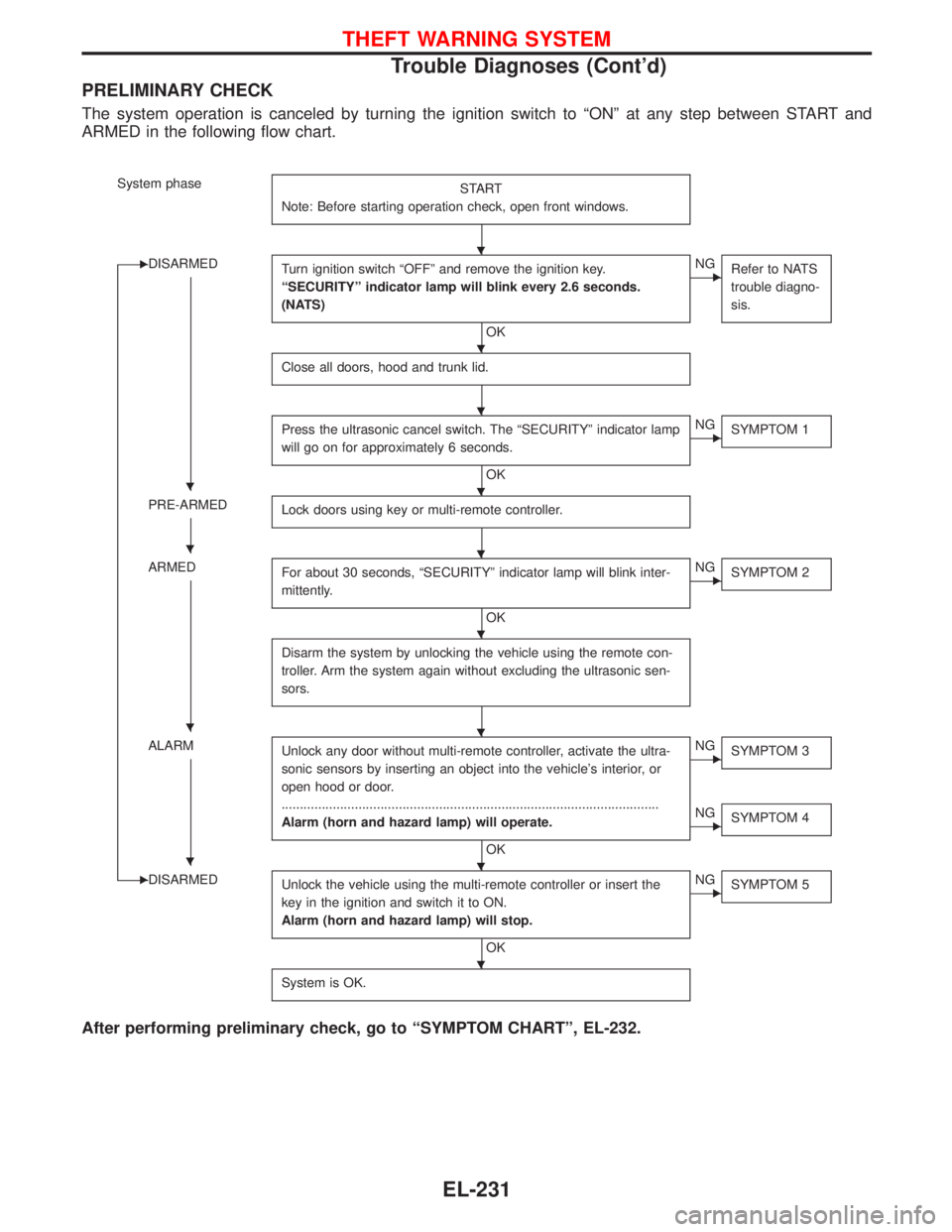
PRELIMINARY CHECK
The system operation is canceled by turning the ignition switch to ªONº at any step between START and
ARMED in the following flow chart.
System phase
START
Note: Before starting operation check, open front windows.
EDISARMED
Turn ignition switch ªOFFº and remove the ignition key.
ªSECURITYº indicator lamp will blink every 2.6 seconds.
(NATS)
OK
ENG
Refer to NATS
trouble diagno-
sis.
Close all doors, hood and trunk lid.
Press the ultrasonic cancel switch. The ªSECURITYº indicator lamp
will go on for approximately 6 seconds.
OK
ENG
SYMPTOM 1
PRE-ARMED
Lock doors using key or multi-remote controller.
ARMED
For about 30 seconds, ªSECURITYº indicator lamp will blink inter-
mittently.
OK
ENG
SYMPTOM 2
Disarm the system by unlocking the vehicle using the remote con-
troller. Arm the system again without excluding the ultrasonic sen-
sors.
ALARM
Unlock any door without multi-remote controller, activate the ultra-
sonic sensors by inserting an object into the vehicle's interior, or
open hood or door.
.......................................................................................................
Alarm (horn and hazard lamp) will operate.
OK
ENG
SYMPTOM 3
ENG
SYMPTOM 4
EDISARMED
Unlock the vehicle using the multi-remote controller or insert the
key in the ignition and switch it to ON.
Alarm (horn and hazard lamp) will stop.
OK
ENG
SYMPTOM 5
System is OK.
After performing preliminary check, go to ªSYMPTOM CHARTº, EL-232.
H
H
H
HH
HH
H
HH
HH
H
THEFT WARNING SYSTEM
Trouble Diagnoses (Cont'd)
EL-231