ignition coil NISSAN TIIDA 2008 Service User Guide
[x] Cancel search | Manufacturer: NISSAN, Model Year: 2008, Model line: TIIDA, Model: NISSAN TIIDA 2008Pages: 2771, PDF Size: 60.61 MB
Page 1336 of 2771

EC-262
< SERVICE INFORMATION >
DTC P0171 FUEL INJECTION SYSTEM FUNCTION
1. Install all removed parts.
2. Start engine and warm it up to normal operating temperature.
3. Check mass air flow sensor signal in Service $01 with GST.
OK or NG
OK >> GO TO 7.
NG >> Check connectors for rusted terminals or loose connections in the mass air flow sensor circuit or
ground. Refer to EC-167
.
7.CHECK FUNCTION OF FUEL INJECTORS
With CONSULT-II
1. Let engine idle.
2. Perform “POWER BALANCE” in “ACTIVE TEST” mode with
CONSULT-II.
3. Make sure that each circuit produces a momentary engine
speed drop.
Without CONSULT-II
1. Let engine idle.
2. Listen to each fuel injector operating sound.
OK or NG
OK >> GO TO 8.
NG >> Perform trouble diagnosis for EC-521
.
8.CHECK FUEL INJECTOR
1. Confirm that the engine is cooled down and there are no fire hazards near the vehicle.
2. Turn ignition switch OFF.
3. Reconnect all harness connectors disconnected.
4. Remove fuel tube assembly. Refer to EM-33
.
Keep fuel hose and all fuel injector connected to fuel tube.
The fuel injector harness connectors should remain connected.
5. Disconnect all ignition coil harness connectors.
6. Prepare pans or saucers under each fuel injector.at idling : 1.0 - 4.0 g·m/sec
at 2,500 rpm : 2.0 - 10.0 g·m/sec
PBIB0133E
Clicking noise should be heard.
PBIB3332E
Page 1343 of 2771
DTC P0172 FUEL INJECTION SYSTEM FUNCTION
EC-269
< SERVICE INFORMATION >
C
D
E
F
G
H
I
J
K
L
MA
EC
N
P OOK or NG
OK >> GO TO 7.
NG >> Check connectors for rusted terminals or loose connections in the mass air flow sensor circuit or
ground. Refer to EC-167
.
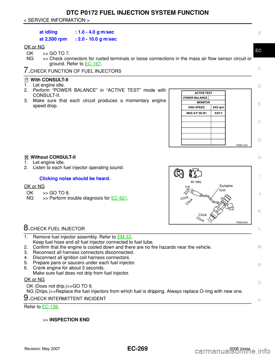
7.CHECK FUNCTION OF FUEL INJECTORS
With CONSULT-II
1. Let engine idle.
2. Perform “POWER BALANCE” in “ACTIVE TEST” mode with
CONSULT-II.
3. Make sure that each circuit produces a momentary engine
speed drop.
Without CONSULT-II
1. Let engine idle.
2. Listen to each fuel injector operating sound.
OK or NG
OK >> GO TO 8.
NG >> Perform trouble diagnosis for EC-521
.
8.CHECK FUEL INJECTOR
1. Remove fuel injector assembly. Refer to EM-33
.
Keep fuel hose and all fuel injector connected to fuel tube.
2. Confirm that the engine is cooled down and there are no fire hazards near the vehicle.
3. Reconnect all harness connectors disconnected.
4. Disconnect all ignition coil harness connectors.
5. Prepare pans or saucers under each fuel injector.
6. Crank engine for about 3 seconds.
Make sure fuel does not drip from fuel injector.
OK or NG
OK (Does not drip.)>>GO TO 9.
NG (Drips.)>>Replace the fuel injectors from which fuel is dripping. Always replace O-ring with new one.
9.CHECK INTERMITTENT INCIDENT
Refer to EC-136
.
>>INSPECTION END at idling : 1.0 - 4.0 g·m/sec
at 2,500 rpm : 2.0 - 10.0 g·m/sec
PBIB0133E
Clicking noise should be heard.
PBIB3332E
Page 1360 of 2771
EC-286
< SERVICE INFORMATION >
DTC P0300 - P0304 MULTIPLE CYLINDER MISFIRE, NO. 1 - 4 CYLINDER MIS-
FIRE
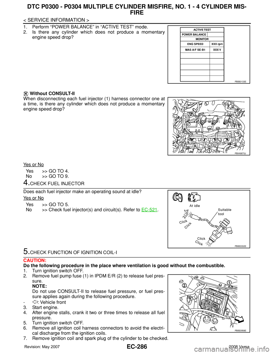
1. Perform “POWER BALANCE” in “ACTIVE TEST” mode.
2. Is there any cylinder which does not produce a momentary
engine speed drop?
Without CONSULT-II
When disconnecting each fuel injector (1) harness connector one at
a time, is there any cylinder which does not produce a momentary
engine speed drop?
Ye s o r N o
Ye s > > G O T O 4 .
No >> GO TO 9.
4.CHECK FUEL INJECTOR
Does each fuel injector make an operating sound at idle?
Ye s o r N o
Ye s > > G O T O 5 .
No >> Check fuel injector(s) and circuit(s). Refer to EC-521
.
5.CHECK FUNCTION OF IGNITION COIL-I
CAUTION:
Do the following procedure in the place where ventilation is good without the combustible.
1. Turn ignition switch OFF.
2. Remove fuel pump fuse (1) in IPDM E/R (2) to release fuel pres-
sure.
NOTE:
Do not use CONSULT-II to release fuel pressure, or fuel pres-
sure applies again during the following procedure.
- : Vehicle front
3. Start engine.
4. After engine stalls, crank it two or three times to release all fuel
pressure.
5. Turn ignition switch OFF.
6. Remove all ignition coil harness connectors to avoid the electri-
cal discharge from the ignition coils.
7. Remove ignition coil and spark plug of the cylinder to be checked.
PBIB0133E
PBIA9870J
PBIB3332E
PBIB2958E
Page 1361 of 2771
DTC P0300 - P0304 MULTIPLE CYLINDER MISFIRE, NO. 1 - 4 CYLINDER MIS-
FIRE
EC-287
< SERVICE INFORMATION >
C
D
E
F
G
H
I
J
K
L
MA
EC
N
P O
8. Crank engine for 5 seconds or more to remove combustion gas in the cylinder.
9. Connect spark plug and harness connector to ignition coil.
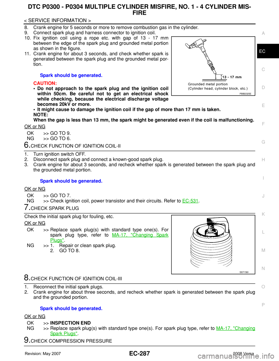
10. Fix ignition coil using a rope etc. with gap of 13 - 17 mm
between the edge of the spark plug and grounded metal portion
as shown in the figure.
11. Crank engine for about 3 seconds, and check whether spark is
generated between the spark plug and the grounded metal por-
tion.
CAUTION:
• Do not approach to the spark plug and the ignition coil
within 50cm. Be careful not to get an electrical shock
while checking, because the electrical discharge voltage
becomes 20kV or more.
• It might cause to damage the ignition coil if the gap of more than 17 mm is taken.
NOTE:
When the gap is less than 13 mm, the spark might be generated even if the coil is malfunctioning.
OK or NG
OK >> GO TO 9.
NG >> GO TO 6.
6.CHECK FUNCTION OF IGNITION COIL-II
1. Turn ignition switch OFF.
2. Disconnect spark plug and connect a known-good spark plug.
3. Crank engine for about 3 seconds, and recheck whether spark is generated between the spark plug and
the grounded metal portion.
OK or NG
OK >> GO TO 7.
NG >> Check ignition coil, power transistor and their circuits. Refer to EC-531
.
7.CHECK SPARK PLUG
Check the initial spark plug for fouling, etc.
OK or NG
OK >> Replace spark plug(s) with standard type one(s). For
spark plug type, refer to MA-17, "
Changing Spark
Plugs".
NG >> 1. Repair or clean spark plug.
2. GO TO 8.
8.CHECK FUNCTION OF IGNITION COIL-III
1. Reconnect the initial spark plugs.
2. Crank engine for about three seconds, and recheck whether spark is generated between the spark plug
and the grounded portion.
OK or NG
OK >>INSPECTION END
NG >> Replace spark plug(s) with standard type one(s). For spark plug type, refer to MA-17, "
Changing
Spark Plugs".
9.CHECK COMPRESSION PRESSURESpark should be generated.
PBIB2325E
Spark should be generated.
SEF156I
Spark should be generated.
Page 1385 of 2771
DTC P0420 THREE WAY CATALYST FUNCTION
EC-311
< SERVICE INFORMATION >
C
D
E
F
G
H
I
J
K
L
MA
EC
N
P O
OK >> GO TO 6.
NG >> Perform EC-523, "
Diagnosis Procedure".
6.CHECK FUNCTION OF IGNITION COIL-I
CAUTION:
Do the following procedure in the place where ventilation is good without the combustible.
1. Turn ignition switch OFF.
2. Remove fuel pump (1) fuse in IPDM E/R (2) to release fuel pres-
sure.
NOTE:
Do not use CONSULT-II to release fuel pressure, or fuel pres-
sure applies again during the following procedure.
- : Vehicle front
3. Start engine.
4. After engine stalls, crank it two or three times to release all fuel
pressure.
5. Turn ignition switch OFF.
6. Remove all ignition coil harness connectors to avoid the electri-
cal discharge from the ignition coils.
7. Remove ignition coil and spark plug of the cylinder to be checked.
8. Crank engine for 5 seconds or more to remove combustion gas in the cylinder.
9. Connect spark plug and harness connector to ignition coil.
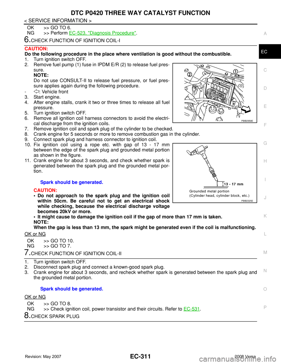
10. Fix ignition coil using a rope etc. with gap of 13 - 17 mm
between the edge of the spark plug and grounded metal portion
as shown in the figure.
11. Crank engine for about 3 seconds, and check whether spark is
generated between the spark plug and the grounded metal por-
tion.
CAUTION:
• Do not approach to the spark plug and the ignition coil
within 50cm. Be careful not to get an electrical shock
while checking, because the electrical discharge voltage
becomes 20kV or more.
• It might cause to damage the ignition coil if the gap of more than 17 mm is taken.
NOTE:
When the gap is less than 13 mm, the spark might be generated even if the coil is malfunctioning.
OK or NG
OK >> GO TO 10.
NG >> GO TO 7.
7.CHECK FUNCTION OF IGNITION COIL-II
1. Turn ignition switch OFF.
2. Disconnect spark plug and connect a known-good spark plug.
3. Crank engine for about 3 seconds, and recheck whether spark is generated between the spark plug and
the grounded metal portion.
OK or NG
OK >> GO TO 8.
NG >> Check ignition coil, power transistor and their circuits. Refer to EC-531
.
8.CHECK SPARK PLUGSpark should be generated.
PBIB2958E
PBIB2325E
Spark should be generated.
Page 1386 of 2771

EC-312
< SERVICE INFORMATION >
DTC P0420 THREE WAY CATALYST FUNCTION
Check the initial spark plug for fouling, etc.
OK or NG
OK >> Replace spark plug(s) with standard type one(s). For
spark plug type, refer to MA-17, "
Changing Spark
Plugs".
NG >> 1. Repair or clean spark plug.
2. GO TO 9.
9.CHECK FUNCTION OF IGNITION COIL-III
1. Reconnect the initial spark plugs.
2. Crank engine for about 3 seconds, and recheck whether spark is generated between the spark plug and
the grounded portion.
OK or NG
OK >>INSPECTION END
NG >> Replace spark plug(s) with standard type one(s). For spark plug type, refer to MA-17, "
Changing
Spark Plugs".
10.CHECK FUEL INJECTOR
1. Turn ignition switch OFF.
2. Remove fuel injector assembly.
Refer to EM-33
.
Keep fuel hose and all fuel injectors connected to fuel tube.
3. Disconnect all ignition coil harness connectors.
4. Reconnect all fuel injector harness connectors disconnected.
5. Turn ignition switch ON.
Make sure fuel does not drip from fuel injector.
OK or NG
OK (Does not drip.)>>GO TO 11.
NG (Drips.)>>Replace the fuel injector(s) from which fuel is dripping.
11 .CHECK INTERMITTENT INCIDENT
Refer to EC-136
.
Trouble is fixed.>>INSPECTION END
Trouble is not fixed.>>Replace three way catalyst (manifold).
SEF156I
Spark should be generated.
Page 1412 of 2771
EC-338
< SERVICE INFORMATION >
DTC P0447 EVAP CANISTER VENT CONTROL VALVE
DTC P0447 EVAP CANISTER VENT CONTROL VALVE
Component DescriptionINFOID:0000000001702844
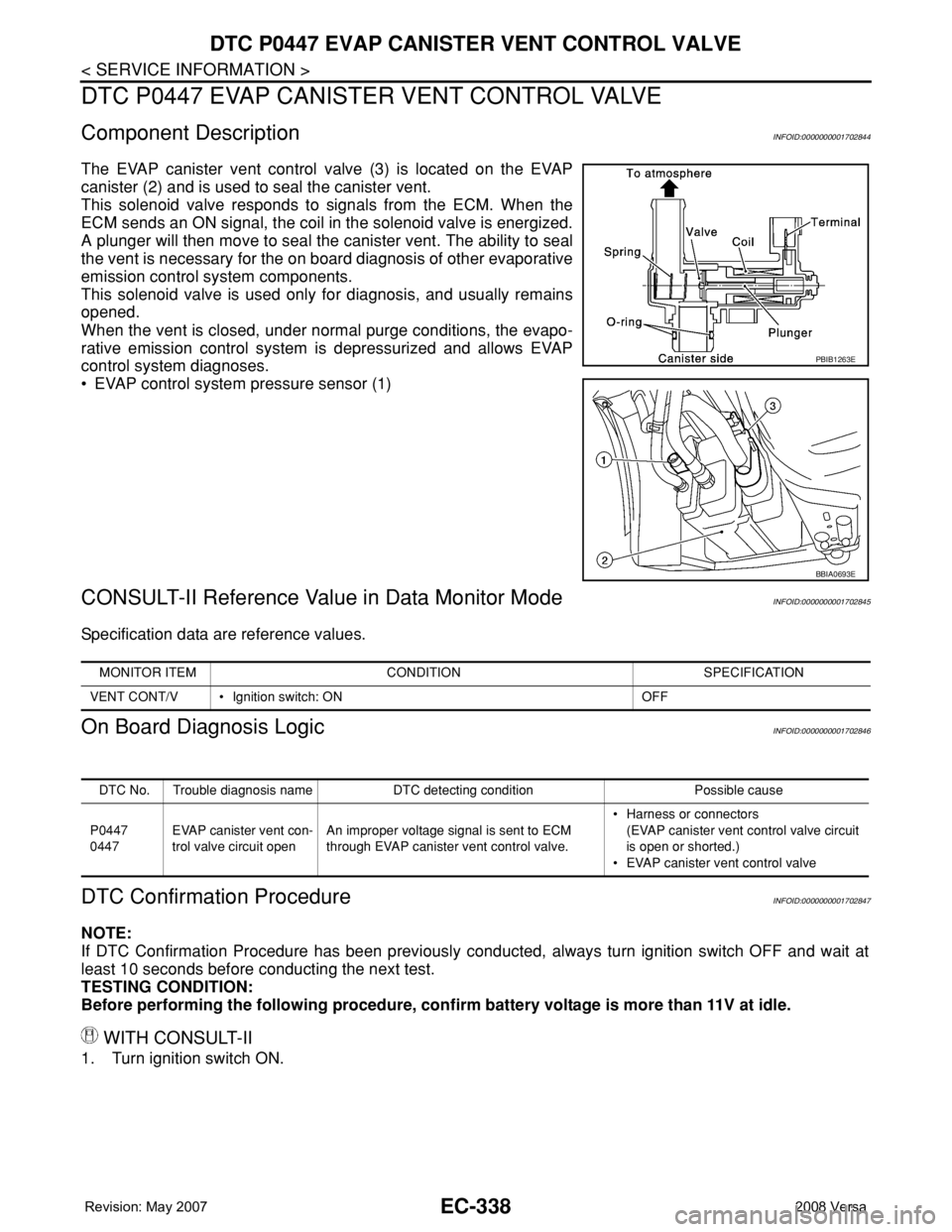
The EVAP canister vent control valve (3) is located on the EVAP
canister (2) and is used to seal the canister vent.
This solenoid valve responds to signals from the ECM. When the
ECM sends an ON signal, the coil in the solenoid valve is energized.
A plunger will then move to seal the canister vent. The ability to seal
the vent is necessary for the on board diagnosis of other evaporative
emission control system components.
This solenoid valve is used only for diagnosis, and usually remains
opened.
When the vent is closed, under normal purge conditions, the evapo-
rative emission control system is depressurized and allows EVAP
control system diagnoses.
• EVAP control system pressure sensor (1)
CONSULT-II Reference Value in Data Monitor ModeINFOID:0000000001702845
Specification data are reference values.
On Board Diagnosis LogicINFOID:0000000001702846
DTC Confirmation ProcedureINFOID:0000000001702847
NOTE:
If DTC Confirmation Procedure has been previously conducted, always turn ignition switch OFF and wait at
least 10 seconds before conducting the next test.
TESTING CONDITION:
Before performing the following procedure, confirm battery voltage is more than 11V at idle.
WITH CONSULT-II
1. Turn ignition switch ON.
PBIB1263E
BBIA0693E
MONITOR ITEM CONDITION SPECIFICATION
VENT CONT/V • Ignition switch: ON OFF
DTC No. Trouble diagnosis name DTC detecting condition Possible cause
P0447
0447EVAP canister vent con-
trol valve circuit openAn improper voltage signal is sent to ECM
through EVAP canister vent control valve.• Harness or connectors
(EVAP canister vent control valve circuit
is open or shorted.)
• EVAP canister vent control valve
Page 1419 of 2771
DTC P0448 EVAP CANISTER VENT CONTROL VALVE
EC-345
< SERVICE INFORMATION >
C
D
E
F
G
H
I
J
K
L
MA
EC
N
P O
DTC P0448 EVAP CANISTER VENT CONTROL VALVE
Component DescriptionINFOID:0000000001702851
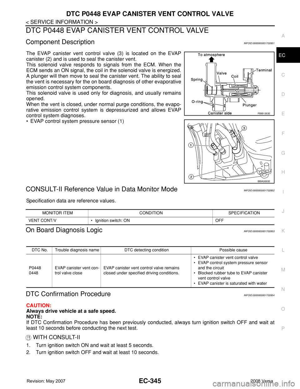
The EVAP canister vent control valve (3) is located on the EVAP
canister (2) and is used to seal the canister vent.
This solenoid valve responds to signals from the ECM. When the
ECM sends an ON signal, the coil in the solenoid valve is energized.
A plunger will then move to seal the canister vent. The ability to seal
the vent is necessary for the on board diagnosis of other evaporative
emission control system components.
This solenoid valve is used only for diagnosis, and usually remains
opened.
When the vent is closed, under normal purge conditions, the evapo-
rative emission control system is depressurized and allows EVAP
control system diagnoses.
• EVAP control system pressure sensor (1)
CONSULT-II Reference Value in Data Monitor ModeINFOID:0000000001702852
Specification data are reference values.
On Board Diagnosis LogicINFOID:0000000001702853
DTC Confirmation ProcedureINFOID:0000000001702854
CAUTION:
Always drive vehicle at a safe speed.
NOTE:
If DTC Confirmation Procedure has been previously conducted, always turn ignition switch OFF and wait at
least 10 seconds before conducting the next test.
WITH CONSULT-II
1. Turn ignition switch ON and wait at least 5 seconds.
2. Turn ignition switch OFF and wait at least 10 seconds.
PBIB1263E
BBIA0693E
MONITOR ITEM CONDITION SPECIFICATION
VENT CONT/V • Ignition switch: ON OFF
DTC No. Trouble diagnosis name DTC detecting condition Possible cause
P0448
0448EVAP canister vent con-
trol valve closeEVAP canister vent control valve remains
closed under specified driving conditions.• EVAP canister vent control valve
• EVAP control system pressure sensor
and the circuit
• Blocked rubber tube to EVAP canister
vent control valve
• EVAP canister is saturated with water
Page 1605 of 2771
IGNITION SIGNAL
EC-531
< SERVICE INFORMATION >
C
D
E
F
G
H
I
J
K
L
MA
EC
N
P O
IGNITION SIGNAL
Component DescriptionINFOID:0000000001703071
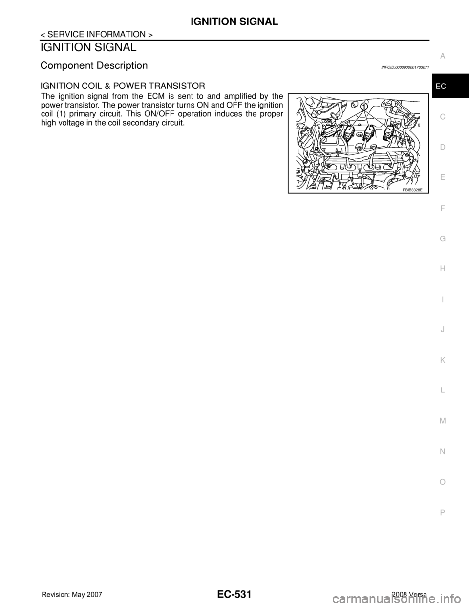
IGNITION COIL & POWER TRANSISTOR
The ignition signal from the ECM is sent to and amplified by the
power transistor. The power transistor turns ON and OFF the ignition
coil (1) primary circuit. This ON/OFF operation induces the proper
high voltage in the coil secondary circuit.
PBIB3328E
Page 1610 of 2771
EC-536
< SERVICE INFORMATION >
IGNITION SIGNAL
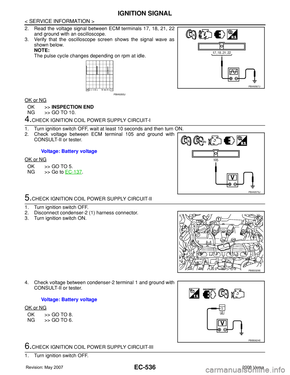
2. Read the voltage signal between ECM terminals 17, 18, 21, 22
and ground with an oscilloscope.
3. Verify that the oscilloscope screen shows the signal wave as
shown below.
NOTE:
The pulse cycle changes depending on rpm at idle.
OK or NG
OK >>INSPECTION END
NG >> GO TO 10.
4.CHECK IGNITION COIL POWER SUPPLY CIRCUIT-I
1. Turn ignition switch OFF, wait at least 10 seconds and then turn ON.
2. Check voltage between ECM terminal 105 and ground with
CONSULT-II or tester.
OK or NG
OK >> GO TO 5.
NG >> Go to EC-137
.
5.CHECK IGNITION COIL POWER SUPPLY CIRCUIT-II
1. Turn ignition switch OFF.
2. Disconnect condenser-2 (1) harness connector.
3. Turn ignition switch ON.
4. Check voltage between condenser-2 terminal 1 and ground with
CONSULT-II or tester.
OK or NG
OK >> GO TO 8.
NG >> GO TO 6.
6.CHECK IGNITION COIL POWER SUPPLY CIRCUIT-III
1. Turn ignition switch OFF.
PBIA9567J
PBIA9265J
Voltage: Battery voltage
PBIA9575J
PBIB3329E
Voltage: Battery voltage
PBIB0624E