oil level NISSAN TIIDA 2008 Service Owner's Manual
[x] Cancel search | Manufacturer: NISSAN, Model Year: 2008, Model line: TIIDA, Model: NISSAN TIIDA 2008Pages: 2771, PDF Size: 60.61 MB
Page 1165 of 2771
TROUBLE DIAGNOSIS
EC-91
< SERVICE INFORMATION >
C
D
E
F
G
H
I
J
K
L
MA
EC
N
P O
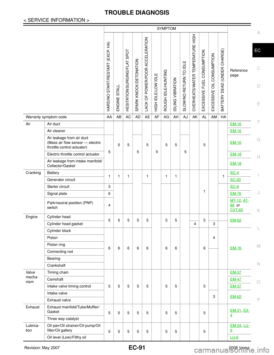
Air Air duct
55555 5EM-16
Air cleanerEM-16
Air leakage from air duct
(Mass air flow sensor — electric
throttle control actuator)
5555EM-16
Electric throttle control actuatorEM-18
Air leakage from intake manifold/
Collector/GasketEM-18
Cranking Battery
111111
11SC-4
Generator circuitSC-20
Starter circuit 3SC-8
Signal plate 6EM-76
Park/neutral position (PNP)
switch4MT-12, AT-
86 or
CVT-65
Engine Cylinder head
55555 55 5EM-62
Cylinder head gasket 4 3
Cylinder block
66666 66 64
EM-76
Piston
Piston ring
Connecting rod
Bearing
Crankshaft
Va l v e
mecha-
nismTiming chain
55555 55 5EM-37
CamshaftEM-47
Intake valve timing controlEM-37
Intake valve
3EM-62
Exhaust valve
Exhaust Exhaust manifold/Tube/Muffler/
Gasket
55555 55 5EM-21
, EX-
4Three way catalyst
Lubrica-
tionOil pan/Oil strainer/Oil pump/Oil
filter/Oil gallery
55555 55 5EM-24
, LU-
9
Oil level (Low)/Filthy oilLU-6
SYMPTOM
Reference
page
HARD/NO START/RESTART (EXCP. HA)
ENGINE STALL
HESITATION/SURGING/FLAT SPOT
SPARK KNOCK/DETONATION
LACK OF POWER/POOR ACCELERATION
HIGH IDLE/LOW IDLE
ROUGH IDLE/HUNTING
IDLING VIBRATION
SLOW/NO RETURN TO IDLE
OVERHEATS/WATER TEMPERATURE HIGH
EXCESSIVE FUEL CONSUMPTION
EXCESSIVE OIL CONSUMPTION
BATTERY DEAD (UNDER CHARGE)
Warranty symptom code AA AB AC AD AE AF AG AH AJ AK AL AM HA
Page 1166 of 2771

EC-92
< SERVICE INFORMATION >
TROUBLE DIAGNOSIS
1 - 6: The numbers refer to the order of inspection.Cooling Radiator/Hose/Radiator filler cap
55555 55 45CO-11
Thermostat 5CO-17
Water pumpCO-16
Water galleryCO-7
Cooling fan
5CO-14
Coolant level (Low)/Contaminat-
ed coolantCO-8
NVIS (NISSAN Vehicle Immobilizer System-
NATS)11BL-210
SYMPTOM
Reference
page
HARD/NO START/RESTART (EXCP. HA)
ENGINE STALL
HESITATION/SURGING/FLAT SPOT
SPARK KNOCK/DETONATION
LACK OF POWER/POOR ACCELERATION
HIGH IDLE/LOW IDLE
ROUGH IDLE/HUNTING
IDLING VIBRATION
SLOW/NO RETURN TO IDLE
OVERHEATS/WATER TEMPERATURE HIGH
EXCESSIVE FUEL CONSUMPTION
EXCESSIVE OIL CONSUMPTION
BATTERY DEAD (UNDER CHARGE)
Warranty symptom code AA AB AC AD AE AF AG AH AJ AK AL AM HA
Page 1169 of 2771
TROUBLE DIAGNOSIS
EC-95
< SERVICE INFORMATION >
C
D
E
F
G
H
I
J
K
L
MA
EC
N
P O
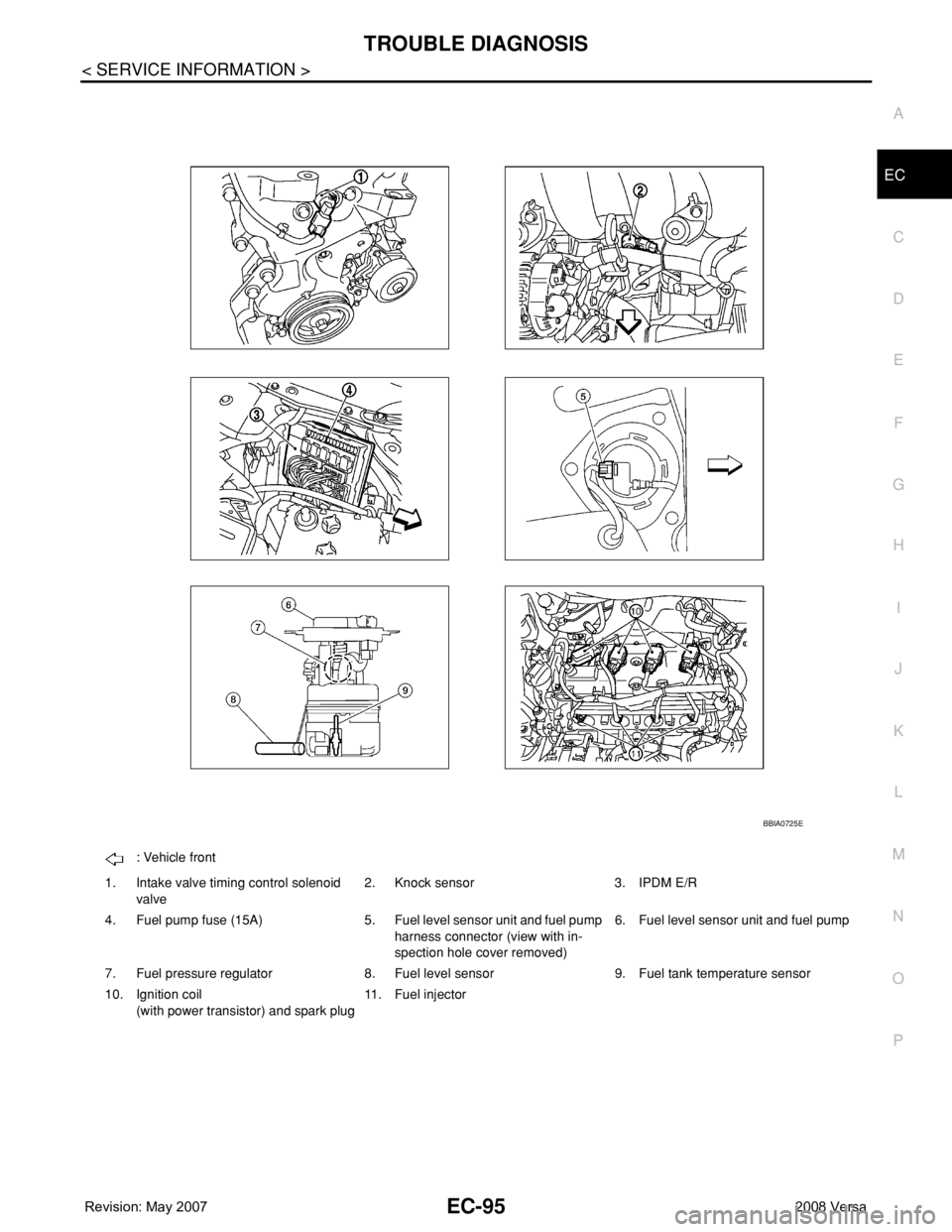
: Vehicle front
1. Intake valve timing control solenoid
valve2. Knock sensor 3. IPDM E/R
4. Fuel pump fuse (15A) 5. Fuel level sensor unit and fuel pump
harness connector (view with in-
spection hole cover removed)6. Fuel level sensor unit and fuel pump
7. Fuel pressure regulator 8. Fuel level sensor 9. Fuel tank temperature sensor
10. Ignition coil
(with power transistor) and spark plug11. Fuel injector
BBIA0725E
Page 1206 of 2771
EC-132
< SERVICE INFORMATION >
TROUBLE DIAGNOSIS - SPECIFICATION VALUE
12.CHECK A/F SENSOR 1 FUNCTION
Perform all DTC Confirmation Procedure related with A/F sensor 1.
• For DTC P0130, refer to EC-206, "
DTC Confirmation Procedure".
• For DTC P0131, refer to EC-213, "
DTC Confirmation Procedure".
• For DTC P0132, refer to EC-219, "
DTC Confirmation Procedure".
• For DTC P0133, refer to EC-225, "
DTC Confirmation Procedure".
• For DTC P2A00, refer to EC-500, "
DTC Confirmation Procedure".
OK or NG
OK >> GO TO 15.
NG >> GO TO 13.
13.CHECK A/F SENSOR 1 CIRCUIT
Perform Diagnostic Procedure according to corresponding DTC.
>> GO TO 14.
14.CHECK “A/F ALPHA-B1”
1. Start engine.
2. Select “A/F ALPHA-B1” in “DATA MONITOR (SPEC)” mode, and make sure that the indication is within
the SP value.
OK or NG
OK >>INSPECTION END
NG >> GO TO 15.
15.DISCONNECT AND RECONNECT ECM HARNESS CONNECTOR
1. Stop the engine.
2. Disconnect ECM harness connector. Check pin terminal and connector for damage, and then reconnect it.
>> GO TO 16.
16.CHECK “A/F ALPHA-B1”
1. Start engine.
2. Select “A/F ALPHA-B1” in “DATA MONITOR (SPEC)” mode, and make sure that the indication is within
the SP value.
OK or NG
OK >>INSPECTION END
NG >> Detect malfunctioning part according to EC-88, "
Symptom Matrix Chart".
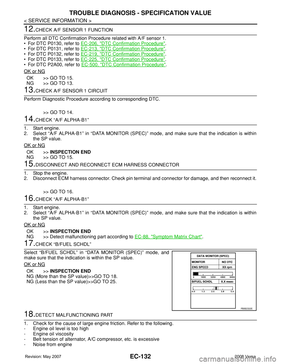
17.CHECK “B/FUEL SCHDL”
Select “B/FUEL SCHDL” in “DATA MONITOR (SPEC)” mode, and
make sure that the indication is within the SP value.
OK or NG
OK >>INSPECTION END
NG (More than the SP value)>>GO TO 18.
NG (Less than the SP value)>>GO TO 25.
18.DETECT MALFUNCTIONING PART
1. Check for the cause of large engine friction. Refer to the following.
- Engine oil level is too high
- Engine oil viscosity
- Belt tension of alternator, A/C compressor, etc. is excessive
- Noise from engine
PBIB2332E
Page 1208 of 2771
EC-134
< SERVICE INFORMATION >
TROUBLE DIAGNOSIS - SPECIFICATION VALUE
3. Perform EC-75, "VIN Registration".
4. Perform EC-76, "
Accelerator Pedal Released Position Learning".
5. Perform EC-76, "
Throttle Valve Closed Position Learning".
6. Perform EC-76, "
Idle Air Volume Learning".
>> GO TO 29.
25.CHECK INTAKE SYSTEM
Check for the cause of uneven air flow through mass air flow sensor. Refer to the following.
• Crushed air ducts
• Malfunctioning seal of air cleaner element
• Uneven dirt of air cleaner element
• Improper specification of intake air system
OK or NG
OK >> GO TO 27.
NG >> Repair or replace malfunctioning part, and then GO TO 26.
26.CHECK “B/FUEL SCHDL”
Select “B/FUEL SCHDL” in “DATA MONITOR (SPEC)” mode, and make sure that the indication is within the
SP value.
OK or NG
OK >>INSPECTION END
NG (Less than the SP value)>>GO TO 27.
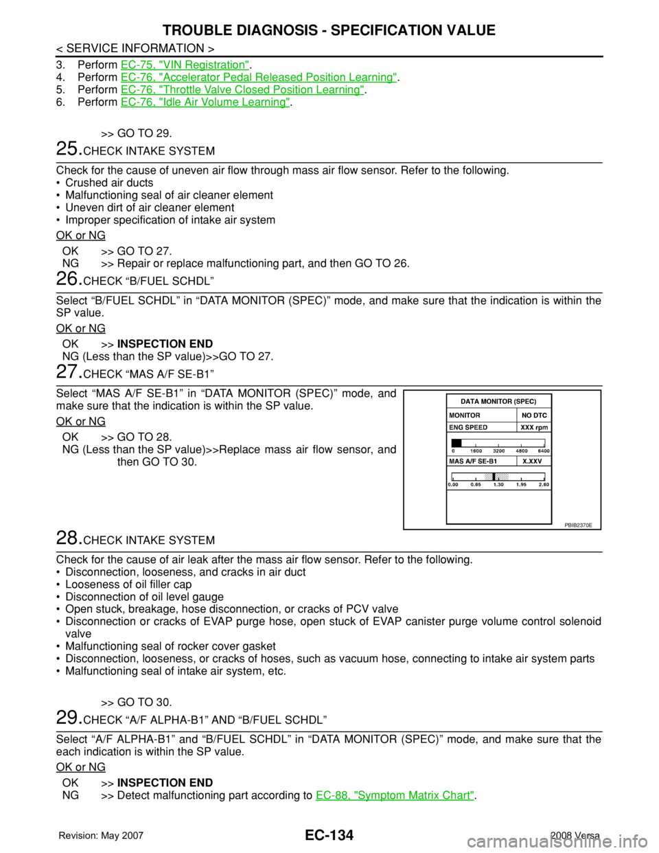
27.CHECK “MAS A/F SE-B1”
Select “MAS A/F SE-B1” in “DATA MONITOR (SPEC)” mode, and
make sure that the indication is within the SP value.
OK or NG
OK >> GO TO 28.
NG (Less than the SP value)>>Replace mass air flow sensor, and
then GO TO 30.
28.CHECK INTAKE SYSTEM
Check for the cause of air leak after the mass air flow sensor. Refer to the following.
• Disconnection, looseness, and cracks in air duct
• Looseness of oil filler cap
• Disconnection of oil level gauge
• Open stuck, breakage, hose disconnection, or cracks of PCV valve
• Disconnection or cracks of EVAP purge hose, open stuck of EVAP canister purge volume control solenoid
valve
• Malfunctioning seal of rocker cover gasket
• Disconnection, looseness, or cracks of hoses, such as vacuum hose, connecting to intake air system parts
• Malfunctioning seal of intake air system, etc.
>> GO TO 30.
29.CHECK “A/F ALPHA-B1” AND “B/FUEL SCHDL”
Select “A/F ALPHA-B1” and “B/FUEL SCHDL” in “DATA MONITOR (SPEC)” mode, and make sure that the
each indication is within the SP value.
OK or NG
OK >>INSPECTION END
NG >> Detect malfunctioning part according to EC-88, "
Symptom Matrix Chart".
PBIB2370E
Page 1487 of 2771
DTC P1217 ENGINE OVER TEMPERATURE
EC-413
< SERVICE INFORMATION >
C
D
E
F
G
H
I
J
K
L
MA
EC
N
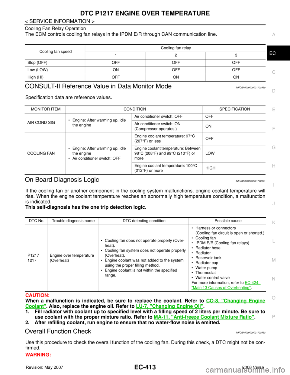
P O Cooling Fan Relay Operation
The ECM controls cooling fan relays in the IPDM E/R through CAN communication line.
CONSULT-II Reference Value in Data Monitor ModeINFOID:0000000001702930
Specification data are reference values.
On Board Diagnosis LogicINFOID:0000000001702931
If the cooling fan or another component in the cooling system malfunctions, engine coolant temperature will
rise. When the engine coolant temperature reaches an abnormally high temperature condition, a malfunction
is indicated.
This self-diagnosis has the one trip detection logic.
CAUTION:
When a malfunction is indicated, be sure to replace the coolant. Refer to CO-8, "
Changing Engine
Coolant". Also, replace the engine oil. Refer to LU-7, "Changing Engine Oil".
1. Fill radiator with coolant up to specified level with a filling speed of 2 liters per minute. Be sure to
use coolant with the proper mixture ratio. Refer to MA-11, "
Anti-freeze Coolant Mixture Ratio".
2. After refilling coolant, run engine to ensure that no water-flow noise is emitted.
Overall Function CheckINFOID:0000000001702932
Use this procedure to check the overall function of the cooling fan. During this check, a DTC might not be con-
firmed.
WARNING:
Cooling fan speedCooling fan relay
123
Stop (OFF) OFF OFF OFF
Low (LOW) ON OFF OFF
High (HI) OFF ON ON
MONITOR ITEM CONDITION SPECIFICATION
AIR COND SIG• Engine: After warming up, idle
the engineAir conditioner switch: OFF OFF
Air conditioner switch: ON
(Compressor operates.)ON
COOLING FAN• Engine: After warming up, idle
the engine
• Air conditioner switch: OFFEngine coolant temperature: 97°C
(207°F) or lessOFF
Engine coolant temperature: Between
98°C (208°F) and 99°C (210°F) or
moreLOW
Engine coolant temperature: 100°C
(212°F) or moreHIGH
DTC No. Trouble diagnosis name DTC detecting condition Possible cause
P1217
1217Engine over temperature
(Overheat)• Cooling fan does not operate properly (Over-
heat).
• Cooling fan system does not operate properly
(Overheat).
• Engine coolant was not added to the system
using the proper filling method.
• Engine coolant is not within the specified
range.• Harness or connectors
(Cooling fan circuit is open or shorted.)
• Cooling fan
• IPDM E/R (Cooling fan relays)
•Radiator hose
•Radiator
• Reservoir tank
•Radiator cap
• Water pump
•Thermostat
• Water control valve
For more information, refer to EC-424,
"Main 13 Causes of Overheating".
Page 1695 of 2771
EM-18
< SERVICE INFORMATION >
INTAKE MANIFOLD
INTAKE MANIFOLD
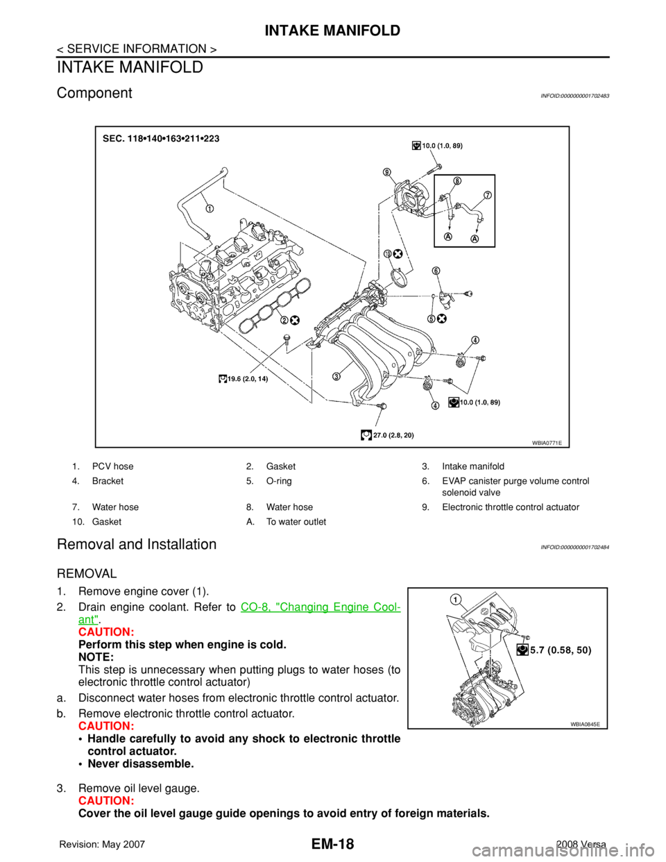
ComponentINFOID:0000000001702483
Removal and InstallationINFOID:0000000001702484
REMOVAL
1. Remove engine cover (1).
2. Drain engine coolant. Refer to CO-8, "
Changing Engine Cool-
ant".
CAUTION:
Perform this step when engine is cold.
NOTE:
This step is unnecessary when putting plugs to water hoses (to
electronic throttle control actuator)
a. Disconnect water hoses from electronic throttle control actuator.
b. Remove electronic throttle control actuator.
CAUTION:
• Handle carefully to avoid any shock to electronic throttle
control actuator.
• Never disassemble.
3. Remove oil level gauge.
CAUTION:
Cover the oil level gauge guide openings to avoid entry of foreign materials.
1. PCV hose 2. Gasket 3. Intake manifold
4. Bracket 5. O-ring 6. EVAP canister purge volume control
solenoid valve
7. Water hose 8. Water hose 9. Electronic throttle control actuator
10. Gasket A. To water outlet
WBIA0771E
WBIA0845E
Page 1701 of 2771
EM-24
< SERVICE INFORMATION >
OIL PAN
OIL PAN
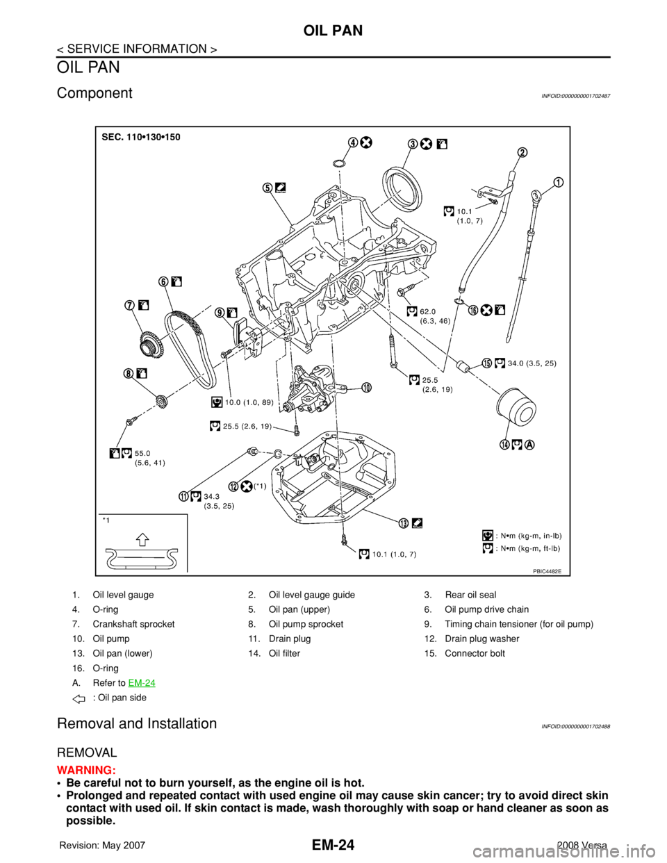
ComponentINFOID:0000000001702487
Removal and InstallationINFOID:0000000001702488
REMOVAL
WARNING:
• Be careful not to burn yourself, as the engine oil is hot.
• Prolonged and repeated contact with used engine oil may cause skin cancer; try to avoid direct skin
contact with used oil. If skin contact is made, wash thoroughly with soap or hand cleaner as soon as
possible.
1. Oil level gauge 2. Oil level gauge guide 3. Rear oil seal
4. O-ring 5. Oil pan (upper) 6. Oil pump drive chain
7. Crankshaft sprocket 8. Oil pump sprocket 9. Timing chain tensioner (for oil pump)
10. Oil pump 11. Drain plug 12. Drain plug washer
13. Oil pan (lower) 14. Oil filter 15. Connector bolt
16. O-ring
A. Refer to EM-24
: Oil pan side
PBIC4482E
Page 1731 of 2771
EM-54
< SERVICE INFORMATION >
CAMSHAFT
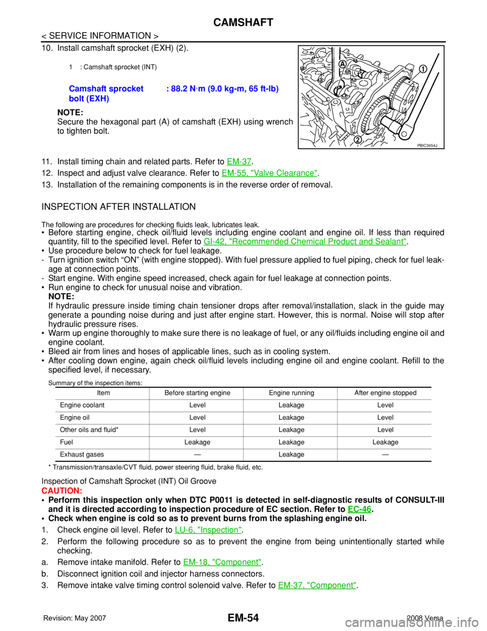
10. Install camshaft sprocket (EXH) (2).
NOTE:
Secure the hexagonal part (A) of camshaft (EXH) using wrench
to tighten bolt.
11. Install timing chain and related parts. Refer to EM-37
.
12. Inspect and adjust valve clearance. Refer to EM-55, "
Valve Clearance".
13. Installation of the remaining components is in the reverse order of removal.
INSPECTION AFTER INSTALLATION
The following are procedures for checking fluids leak, lubricates leak.
• Before starting engine, check oil/fluid levels including engine coolant and engine oil. If less than required
quantity, fill to the specified level. Refer to GI-42, "
Recommended Chemical Product and Sealant".
• Use procedure below to check for fuel leakage.
- Turn ignition switch “ON” (with engine stopped). With fuel pressure applied to fuel piping, check for fuel leak-
age at connection points.
- Start engine. With engine speed increased, check again for fuel leakage at connection points.
• Run engine to check for unusual noise and vibration.
NOTE:
If hydraulic pressure inside timing chain tensioner drops after removal/installation, slack in the guide may
generate a pounding noise during and just after engine start. However, this is normal. Noise will stop after
hydraulic pressure rises.
• Warm up engine thoroughly to make sure there is no leakage of fuel, or any oil/fluids including engine oil and
engine coolant.
• Bleed air from lines and hoses of applicable lines, such as in cooling system.
• After cooling down engine, again check oil/fluid levels including engine oil and engine coolant. Refill to the
specified level, if necessary.
Summary of the inspection items:
* Transmission/transaxle/CVT fluid, power steering fluid, brake fluid, etc.
Inspection of Camshaft Sprocket (INT) Oil Groove
CAUTION:
• Perform this inspection only when DTC P0011 is detected in self-diagnostic results of CONSULT-III
and it is directed according to inspection procedure of EC section. Refer to EC-46
.
• Check when engine is cold so as to prevent burns from the splashing engine oil.
1. Check engine oil level. Refer to LU-6, "
Inspection".
2. Perform the following procedure so as to prevent the engine from being unintentionally started while
checking.
a. Remove intake manifold. Refer to EM-18, "
Component".
b. Disconnect ignition coil and injector harness connectors.
3. Remove intake valve timing control solenoid valve. Refer to EM-37, "
Component".
1 : Camshaft sprocket (INT)
Camshaft sprocket
bolt (EXH): 88.2 N·m (9.0 kg-m, 65 ft-lb)
PBIC3454J
Item Before starting engine Engine running After engine stopped
Engine coolant Level Leakage Level
Engine oil Level Leakage Level
Other oils and fluid* Level Leakage Level
Fuel Leakage Leakage Leakage
Exhaust gases — Leakage —
Page 1740 of 2771
CYLINDER HEAD
EM-63
< SERVICE INFORMATION >
C
D
E
F
G
H
I
J
K
L
MA
EM
N
P O
• If the engine speed is out of the specified range, check battery liquid for proper gravity. Check engine
speed again with normal battery gravity.
• If compression pressure is below minimum value, check valve clearances and parts associated with
combustion chamber (Valve, valve seat, piston, piston ring, cylinder bore, cylinder head, cylinder head
gasket). After the checking, measure the compression pressure again.
• If some cylinder has low compression pressure, pour small amount of engine oil into the spark plug hole
of the cylinder to re-check it for compression.
- If the added engine oil improves the compression, piston rings may be worn out or damaged. Check pis-
ton rings and replace if necessary.
- If the compression pressure remains at low level despite the addition of engine oil, valves may be mal-
functioning. Check valves for damage. Replace valve or valve seat accordingly.
• If two adjacent cylinders have respectively low compression pressure and their compression remains
low even after the addition of engine oil, cylinder head gasket is leaking. In such a case, replace cylinder
head gasket.
9. After inspection is completed, install removed parts.
10. Start the engine, and confirm that the engine runs smoothly.
11. Perform trouble diagnosis. If DTC appears, erase it. Refer to EC-81
.
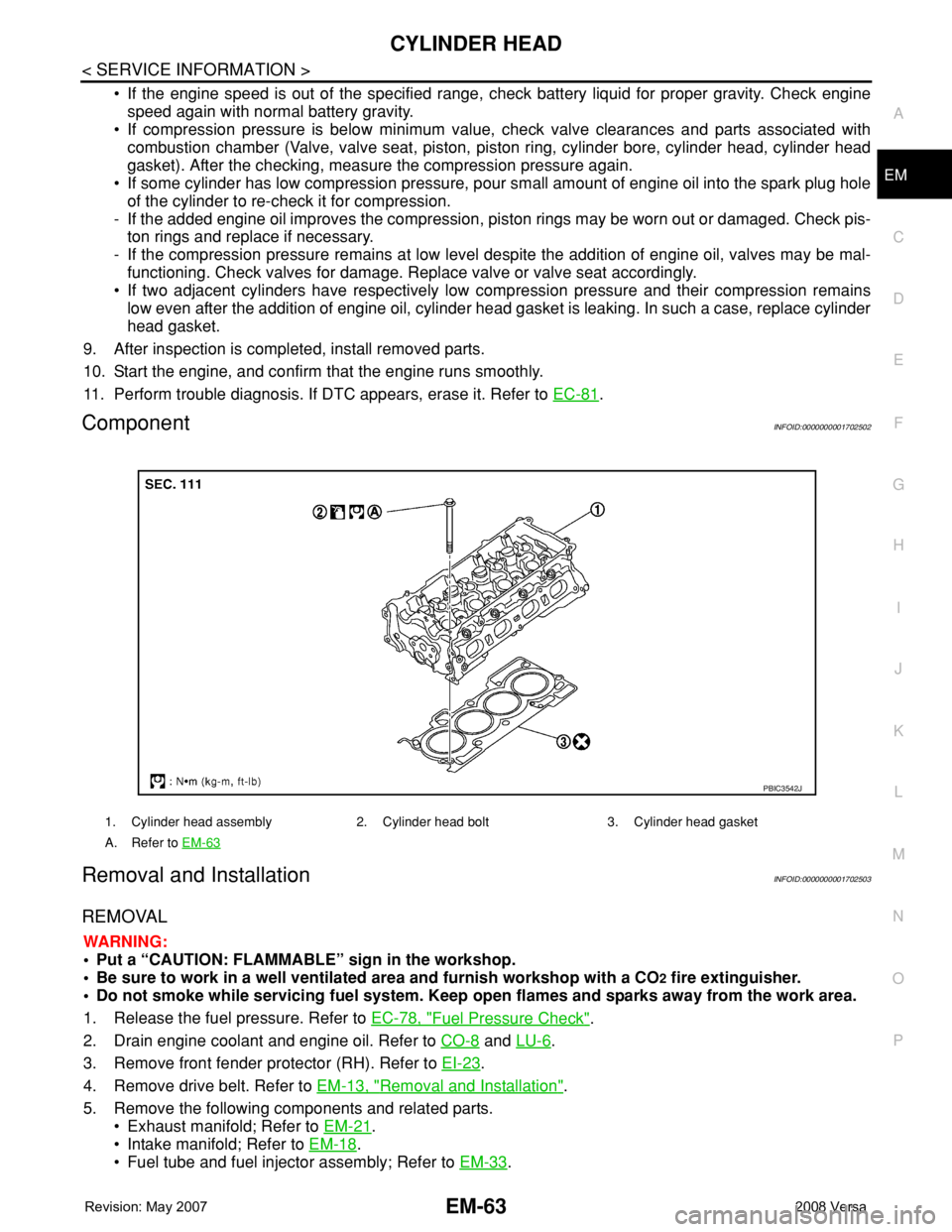
ComponentINFOID:0000000001702502
Removal and InstallationINFOID:0000000001702503
REMOVAL
WARNING:
• Put a “CAUTION: FLAMMABLE” sign in the workshop.
• Be sure to work in a well ventilated area and furnish workshop with a CO
2 fire extinguisher.
• Do not smoke while servicing fuel system. Keep open flames and sparks away from the work area.
1. Release the fuel pressure. Refer to EC-78, "
Fuel Pressure Check".
2. Drain engine coolant and engine oil. Refer to CO-8
and LU-6.
3. Remove front fender protector (RH). Refer to EI-23
.
4. Remove drive belt. Refer to EM-13, "
Removal and Installation".
5. Remove the following components and related parts.
• Exhaust manifold; Refer to EM-21
.
• Intake manifold; Refer to EM-18
.
• Fuel tube and fuel injector assembly; Refer to EM-33
.
1. Cylinder head assembly 2. Cylinder head bolt 3. Cylinder head gasket
A. Refer to EM-63
PBIC3542J