tire pressure NISSAN TIIDA 2008 Service Owner's Manual
[x] Cancel search | Manufacturer: NISSAN, Model Year: 2008, Model line: TIIDA, Model: NISSAN TIIDA 2008Pages: 2771, PDF Size: 60.61 MB
Page 2564 of 2771

REAR SUSPENSION ASSEMBLY
RSU-5
< SERVICE INFORMATION >
C
D
F
G
H
I
J
K
L
MA
B
RSU
N
O
P
REAR SUSPENSION ASSEMBLY
On-Vehicle Inspection and ServiceINFOID:0000000001703736
Make sure the mounting conditions (looseness, backlash) of each component and component conditions
(wear, damage) are within specifications.
SHOCK ABSORBER INSPECTION
Check shock absorber for oil leakage, damage and replace it if necessary.
Wheel AlignmentInspectionINFOID:0000000001703737
DESCRIPTION
Measure wheel alignment under unladen conditions.
NOTE:
“Unladen conditions” means that fuel, engine coolant, and lubricant are full. Spare tire, jack, hand tools and
mats are in designated positions.
PRELIMINARY
Check the following:
1. Tires for improper air pressure and wear.
2. Road wheels for runout. Refer to WT-5
.
3. Wheel bearing axial end play. Refer to RAX-4, "
On-Vehicle Inspection and Service" .
4. Shock absorber operation.
5. Each mounting part of suspension for looseness and deformation.
6. Rear suspension beam for cracks, deformation, and other damage.
7. Vehicle height (posture).
GENERAL INFORMATION AND RECOMMENDATIONS
1. A Four-Wheel Thrust Alignment should be performed.
• This type of alignment is recommended for any NISSAN vehicle.
• The four-wheel “thrust” process helps ensure that the vehicle is properly aligned and the steering wheel
is centered.
• The alignment machine itself should be capable of accepting any NISSAN vehicle.
• The alignment machine should be checked to ensure that it is level.
2. Make sure the alignment machine is properly calibrated.
• Your alignment machine should be regularly calibrated in order to give correct information.
• Check with the manufacturer of your specific alignment machine for their recommended Service/Cali-
bration Schedule.
THE ALIGNMENT PROCESS
IMPORTANT: Use only the alignment specifications listed in this Service Manual. Refer to RSU-12, "Wheel
Alignment (Unladen*)" .
1. When displaying the alignment settings, many alignment machines use “indicators”: (Green/red, plus or
minus, Go/No Go). Do NOT use these indicators.
• The alignment specifications programmed into your alignment machine that operate these indicators
may not be correct.
• This may result in an ERROR.
2. Some newer alignment machines are equipped with an optional “Rolling Compensation” method to “com-
pensate” the sensors (alignment targets or head units). Do NOT use this “Rolling Compensation”
method.
• Use the “Jacking Compensation” method. After installing the alignment targets or head units, raise the
vehicle and rotate the wheels 1/2 turn both ways.
• See Instructions in the alignment machine you are using for more information.
CAMBER INSPECTION
Page 2681 of 2771

COLLISION DIAGNOSIS
SRS-47
< ON-VEHICLE REPAIR >
C
D
E
F
G
I
J
K
L
MA
B
SRS
N
O
P
For Side and Rollover CollisionINFOID:0000000001703937
Check the SRS components using the following table.
• After the work is completed, perform self-diagnosis to check that no malfunction is detected. Refer to SRS-
18, "SRS Operation Check".
WHEN SRS IS ACTIVATED IN THE SIDE OR ROLLOVER COLLISION
1. Replace the following components:
- Front seat back assembly (on the side on which side air bag is activated)
- Diagnosis sensor unit
- (LH or RH) side air bag (satellite) sensor (on the side on which side air bag is activated)
2. Check the SRS components and the related parts using the following table.
- Replace any SRS components and the related parts showing visible signs of damage (dents, cracks,
deformation).
3. Conduct self-diagnosis using CONSULT-III and “AIR BAG” warning lamp. Refer to SRS-18, "
SRS Opera-
tion Check" for details. Ensure entire SRS operates properly.
WHEN SRS IS NOT ACTIVATED IN THE SIDE OR ROLLOVER COLLISION
1. Check the SRS components and the related parts using the following table.
- If the front seat back assembly is damaged, the front seat back assembly must be replaced.
2. Conduct self-diagnosis using CONSULT-III and “AIR BAG” warning lamp. Refer to SRS-18, "
SRS Opera-
tion Check" for details. Ensure entire SRS operates properly.
SRS INSPECTION (FOR SIDE AND ROLLOVER COLLISION)
Steering wheel 1. Visually check steering wheel for deformities.
2. Check harness (built into steering wheel) and connectors for damage, and terminals for deformities.
3. Install driver air bag module into the steering wheel to check fit and alignment with the wheel.
4. Check steering wheel for excessive free play.
5. If no damage is found, reinstall.
6. If damaged—REPLACE.
Spiral cable If the driver front air
bag has deployed:
REPLACE the spiral
cable.If the driver front air bag has not deployed:
1. Visually check spiral cable and combination switch for damage.
2. Check connectors and protective tape for damage.
3. Check steering wheel for noise, binding or heavy operation.
4. If no damage is found, reinstall.
5. If damaged—REPLACE.
Occupant classifica-
tion system (Passen-
ger seat)1. Remove passenger seat.
2. Check control unit case for dents, cracks of deformities.
3. Check connectors and pressure sensor tube for damage, and terminals for deformities.
4. Check seat frame and cushion pan for dents or deformities.
5. If no damage is found, reinstall seat with new fasteners.
6. If damaged — REPLACE seat cushion assembly with new fasteners.
Harness and connec-
tors1. Check connectors for poor connection, damage, and terminals for deformities.
2. Check harness for binding, chafing, cuts, or deformities.
3. If no damage is found, reinstall the harness and connectors.
4. If damaged—REPLACE the damaged harness. Do not attempt to repair, splice or modify any SRS har-
ness.
Instrument panel If the passenger front
air bag has deployed:
REPLACE the instru-
ment panel assembly.If the passenger front air bag has NOT deployed:
1. Visually check instrument panel for damage.
2. If no damage is found, reinstall the instrument panel.
3. If damaged—REPLACE the instrument panel. Part SRS is activated SRS is NOT activated
Page 2686 of 2771
![NISSAN TIIDA 2008 Service Owners Manual PRECAUTIONS
STC-3
< SERVICE INFORMATION >[EPS]
C
D
E
F
H
I
J
K
L
MA
B
STC
N
O
P
• Check any possible causes by interviewing the symptom and it’s condition from the customer if any
malfunction, suc](/img/5/57399/w960_57399-2685.png "NISSAN TIIDA 2008 Service Owners Manual PRECAUTIONS
STC-3
< SERVICE INFORMATION >[EPS]
C
D
E
F
H
I
J
K
L
MA
B
STC
N
O
P
• Check any possible causes by interviewing the symptom and it’s condition from the customer if any
malfunction, suc")
PRECAUTIONS
STC-3
< SERVICE INFORMATION >[EPS]
C
D
E
F
H
I
J
K
L
MA
B
STC
N
O
P
• Check any possible causes by interviewing the symptom and it’s condition from the customer if any
malfunction, such as EPS warning lamp turns ON, occurs.
• Check if air pressure and size of tires are proper, the specified part is used for the steering wheel,
and control unit is genuine part.
• Check if the connection of steering column assembly and steering gear assembly is proper (there is
not looseness of mounting bolts, damage of rods, boots or sealants, and leakage of grease, etc).
• Check if the wheel alignment is adjusted properly.
• Check if there is any damage or modification to suspension or body resulting in increased weight or
altered ground clearance.
• Check if installation conditions of each link and suspension are proper.
• Check if the battery voltage is proper
• Check connection conditions of each connector are proper.
• Before connecting or disconnecting the EPS control unit har-
ness connector, turn ignition switch “OFF” and disconnect
battery ground cable. Because battery voltage is applied to
EPS control unit even if ignition switch is turned “OFF”.
• When connecting or disconnecting pin connectors into or
from EPS control unit, take care not to damage pin terminals
(bend or break).
When connecting pin connectors, make sure that there are no
bends or breaks on EPS control unit pin terminal.
• Before replacing EPS control unit, perform EPS control unit
input/output signal inspection and make sure whether EPS
control unit functions properly or not. Refer to STC-9, "
EPS
Control Unit Input/Output Signal Reference Value".
SEF289H
SEF291H
SDIA1848E
Page 2709 of 2771

WT-1
SUSPENSION
C
D
F
G
H
I
J
K
L
M
SECTION WT
A
B
WT
N
O
PCONTENTS
ROAD WHEELS & TIRES
SERVICE INFORMATION ............................2
PRECAUTIONS ...................................................2
Precaution for Supplemental Restraint System
(SRS) "AIR BAG" and "SEAT BELT PRE-TEN-
SIONER" ...................................................................
2
PREPARATION ...................................................3
Special Service Tool .................................................3
Commercial Service Tool ..........................................3
NOISE, VIBRATION AND HARSHNESS
(NVH) TROUBLESHOOTING .............................
4
NVH Troubleshooting Chart ......................................4
ROAD WHEEL ....................................................5
Inspection ..................................................................5
ROAD WHEEL TIRE ASSEMBLY ......................6
Balancing Wheels .....................................................6
Rotation .....................................................................6
TIRE PRESSURE MONITORING SYSTEM ........7
System Component ...................................................7
System Description ...................................................7
CAN COMMUNICATION .....................................9
System Description ...................................................9
TROUBLE DIAGNOSES ....................................10
Wiring Diagram- T/WARN - .....................................10
Terminal and Reference Value for BCM .................10
ID Registration Procedure .......................................11
Transmitter Wake Up Operation .............................12
CONSULT-III Function (BCM) .................................12
How to Perform Trouble Diagnosis for Quick and
Accurate Repair .......................................................
13
Preliminary Check ...................................................14
Self-Diagnosis .........................................................15
Flash Code/Symptom Chart ....................................16
TROUBLE DIAGNOSIS FOR SELF-DIAG-
NOSTIC ITEMS .................................................
18
Data from Transmitter Not Being Received .............18
Transmitter Malfunction ...........................................18
Transmitter Pressure Malfunction ............................19
Vehicle Speed Signal ..............................................19
TROUBLE DIAGNOSIS FOR SYMPTOMS ......20
Low Tire Pressure Warning Lamp Does Not Come
On When Ignition Switch Is Turned On ...................
20
Low Tire Pressure Warning Lamp Stays On When
Ignition Switch Is Turned On ...................................
20
Low Tire Pressure Warning Lamp Flashes When
Ignition Switch Is Turned On ...................................
21
Hazard Warning Lamps Flash When Ignition
Switch Is Turned On ................................................
22
ID Registration Cannot Be Completed ....................22
REMOVAL AND INSTALLATION .....................23
Transmitter (Pressure Sensor) ................................23
SERVICE DATA AND SPECIFICATIONS
(SDS) .................................................................
25
Road Wheel .............................................................25
Tire ..........................................................................25
Page 2712 of 2771

WT-4
< SERVICE INFORMATION >
NOISE, VIBRATION AND HARSHNESS (NVH) TROUBLESHOOTING
NOISE, VIBRATION AND HARSHNESS (NVH) TROUBLESHOOTING
NVH Troubleshooting ChartINFOID:0000000001703747
Use the chart below to help you find the cause of the symptom. If necessary, repair or replace these parts.
×: ApplicableReference page
FAX-5WT-5
WT-6
WT-25—
—
—
—
FAX-4, "
NVH Troubleshooting Chart
",
FSU-5, "
NVH Troubleshooting Chart
"
RAX-3, "
NVH Troubleshooting Chart
",
RSU-4, "
NVH Troubleshooting Chart
"
Refer to TIRES in this chart
Refer to ROAD WHEEL in this chart
FAX-4, "
NVH Troubleshooting Chart
"
BR-4, "
NVH Troubleshooting Chart
"
PS-5, "
NVH Troubleshooting Chart
"
Possible cause and SUSPECTED PARTS
Improper installation, looseness
Out-of-round
Imbalance
Incorrect tire pressure
Uneven tire wear
Deformation or damage
Non-uniformity
Incorrect tire size
FRONT AXLE AND FRONT SUSPENSION
REAR AXLE AND REAR SUSPENSION
TIRES
ROAD WHEELS
DRIVE SHAFT
BRAKE
STEERING
SymptomTIRESNoise× ×××××× × × ××××
Shake× ××××× × × × ××××
Vibration××××××
Shimmy× ××××××× × × × ××
Shudder× ××××× × × × × ××
Poor quality ride
or handling× ××××× × × × ×
ROAD WHEELNoise× ×× × × × × ×××
Shake× ×× × × × × ×××
Shimmy, Shud-
der×××× ×××××
Poor quality ride
or handling××× × × × ×
Page 2715 of 2771
TIRE PRESSURE MONITORING SYSTEM
WT-7
< SERVICE INFORMATION >
C
D
F
G
H
I
J
K
L
MA
B
WT
N
O
P
TIRE PRESSURE MONITORING SYSTEM
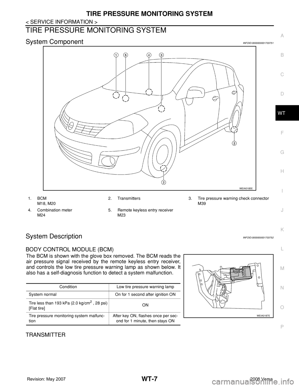
System ComponentINFOID:0000000001703751
System DescriptionINFOID:0000000001703752
BODY CONTROL MODULE (BCM)
The BCM is shown with the glove box removed. The BCM reads the
air pressure signal received by the remote keyless entry receiver,
and controls the low tire pressure warning lamp as shown below. It
also has a self-diagnosis function to detect a system malfunction.
TRANSMITTER
WEIA0185E
1. BCM
M18, M202. Transmitters 3. Tire pressure warning check connector
M39
4. Combination meter
M245. Remote keyless entry receiver
M23
Condition Low tire pressure warning lamp
System normal On for 1 second after ignition ON
Tire less than 193 kPa (2.0 kg/cm
2 , 28 psi)
[Flat tire]ON
Tire pressure monitoring system malfunc-
tionAfter key ON, flashes once per sec-
ond for 1 minute, then stays ON
WEIA0187E
Page 2716 of 2771
WT-8
< SERVICE INFORMATION >
TIRE PRESSURE MONITORING SYSTEM
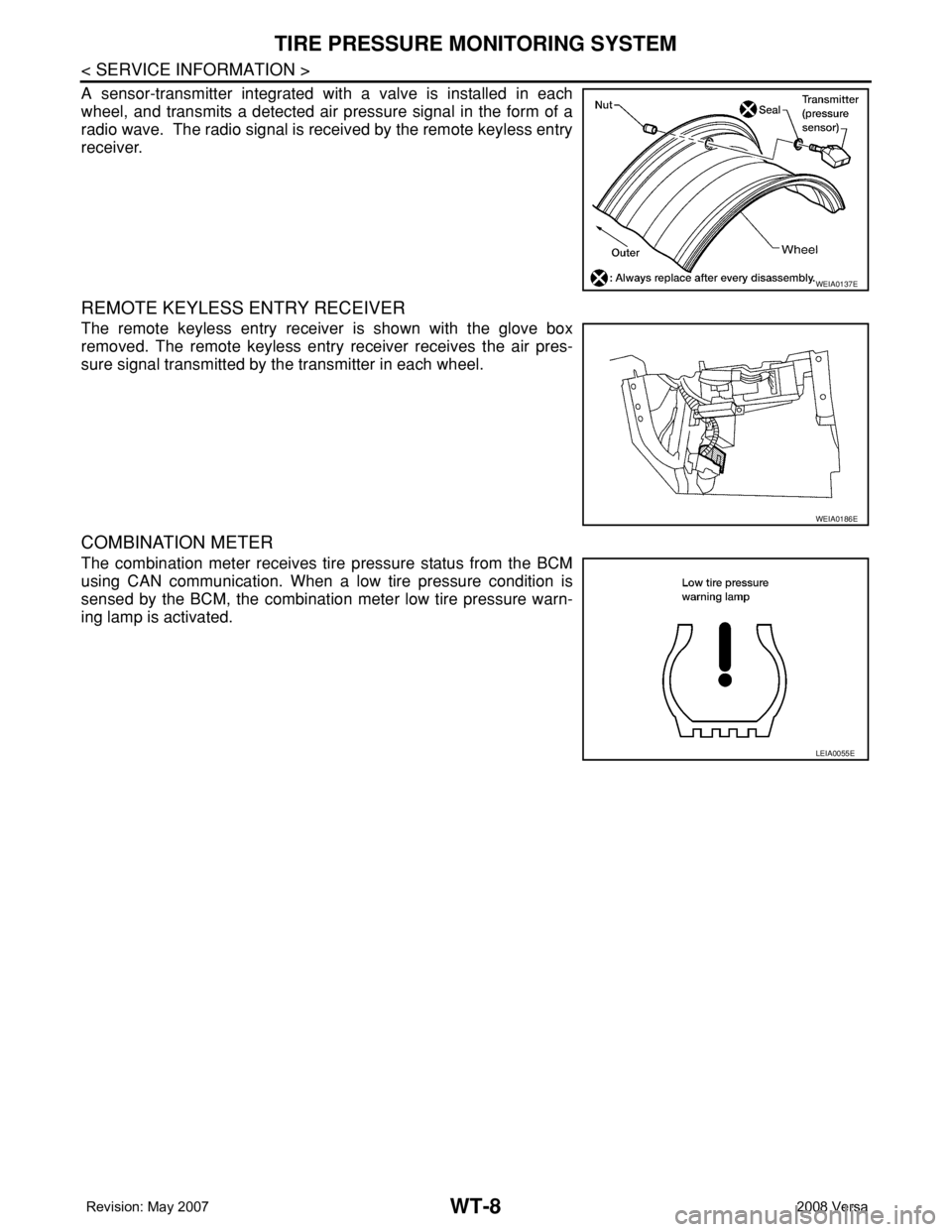
A sensor-transmitter integrated with a valve is installed in each
wheel, and transmits a detected air pressure signal in the form of a
radio wave. The radio signal is received by the remote keyless entry
receiver.
REMOTE KEYLESS ENTRY RECEIVER
The remote keyless entry receiver is shown with the glove box
removed. The remote keyless entry receiver receives the air pres-
sure signal transmitted by the transmitter in each wheel.
COMBINATION METER
The combination meter receives tire pressure status from the BCM
using CAN communication. When a low tire pressure condition is
sensed by the BCM, the combination meter low tire pressure warn-
ing lamp is activated.
WEIA0137E
WEIA0186E
LEIA0055E
Page 2719 of 2771
TROUBLE DIAGNOSES
WT-11
< SERVICE INFORMATION >
C
D
F
G
H
I
J
K
L
MA
B
WT
N
O
P
ID Registration ProcedureINFOID:0000000001703756
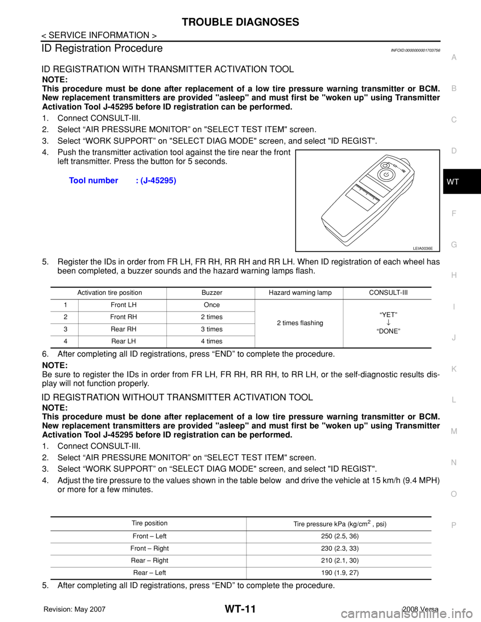
ID REGISTRATION WITH TRANSMITTER ACTIVATION TOOL
NOTE:
This procedure must be done after replacement of a low tire pressure warning transmitter or BCM.
New replacement transmitters are provided "asleep" and must first be "woken up" using Transmitter
Activation Tool J-45295 before ID registration can be performed.
1. Connect CONSULT-III.
2. Select “AIR PRESSURE MONITOR” on "SELECT TEST ITEM" screen.
3. Select “WORK SUPPORT” on "SELECT DIAG MODE" screen, and select "ID REGIST".
4. Push the transmitter activation tool against the tire near the front
left transmitter. Press the button for 5 seconds.
5. Register the IDs in order from FR LH, FR RH, RR RH and RR LH. When ID registration of each wheel has
been completed, a buzzer sounds and the hazard warning lamps flash.
6. After completing all ID registrations, press “END” to complete the procedure.
NOTE:
Be sure to register the IDs in order from FR LH, FR RH, RR RH, to RR LH, or the self-diagnostic results dis-
play will not function properly.
ID REGISTRATION WITHOUT TRANSMITTER ACTIVATION TOOL
NOTE:
This procedure must be done after replacement of a low tire pressure warning transmitter or BCM.
New replacement transmitters are provided "asleep" and must first be "woken up" using Transmitter
Activation Tool J-45295 before ID registration can be performed.
1. Connect CONSULT-III.
2. Select “AIR PRESSURE MONITOR” on “SELECT TEST ITEM" screen.
3. Select “WORK SUPPORT” on “SELECT DIAG MODE" screen, and select "ID REGIST".
4. Adjust the tire pressure to the values shown in the table below and drive the vehicle at 15 km/h (9.4 MPH)
or more for a few minutes.
5. After completing all ID registrations, press “END” to complete the procedure.Tool number : (J-45295)
LEIA0036E
Activation tire position Buzzer Hazard warning lamp CONSULT-III
1 Front LH Once
2 times flashing“YET”
↓
“DONE” 2 Front RH 2 times
3 Rear RH 3 times
4 Rear LH 4 times
Tire position
Tire pressure kPa (kg/cm2 , psi)
Front – Left 250 (2.5, 36)
Front – Right 230 (2.3, 33)
Rear – Right 210 (2.1, 30)
Rear – Left 190 (1.9, 27)
Page 2720 of 2771
WT-12
< SERVICE INFORMATION >
TROUBLE DIAGNOSES
6. Inflate all tires to proper pressure. Refer to WT-25, "Tire" .
Transmitter Wake Up OperationINFOID:0000000001703757
NOTE:
This procedure must be done after replacement of a low tire pressure warning transmitter or BCM.
New replacement transmitters are provided "asleep" and must first be "woken up" using Transmitter
Activation Tool J-45295 before ID registration can be performed.
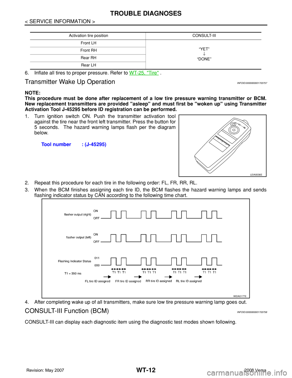
1. Turn ignition switch ON. Push the transmitter activation tool
against the tire near the front left transmitter. Press the button for
5 seconds. The hazard warning lamps flash per the diagram
below.
2. Repeat this procedure for each tire in the following order: FL, FR, RR, RL.
3. When the BCM finishes assigning each tire ID, the BCM flashes the hazard warning lamps and sends
flashing indicator status by CAN according to the following time chart.
4. After completing wake up of all transmitters, make sure low tire pressure warning lamp goes out.
CONSULT-III Function (BCM)INFOID:0000000001703758
CONSULT-III can display each diagnostic item using the diagnostic test modes shown following.
Activation tire position CONSULT-III
Front LH
“YET”
↓
“DONE” Front RH
Rear RH
Rear LH
Tool number : (J-45295)
LEIA0036E
WEIA0177E
Page 2722 of 2771
WT-14
< SERVICE INFORMATION >
TROUBLE DIAGNOSES
Preliminary Check
INFOID:0000000001703760
BASIC INSPECTION
1.CHECK ALL TIRE PRESSURES
Check all tire pressures. Refer to WT-25, "
Tire" .
OK or NG
OK >> GO TO 2.
NG >> Adjust tire pressure to specified value.
2.CHECK LOW TIRE PRESSURE WARNING LAMP ACTIVATION
Check low tire pressure warning lamp activation.
Does warning lamp activate for 1 second when ignition switch is turned ON?
YES >> GO TO 3.
NO >> GO TO WT-20, "
Low Tire Pressure Warning Lamp Does Not Come On When Ignition Switch Is
Turned On" .
3.CHECK BCM CONNECTOR
1. Disconnect BCM harness connector.
2. Check terminals for damage or loose connection.
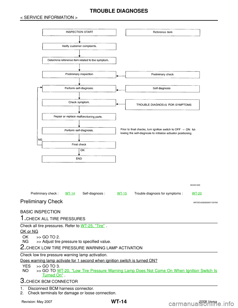
Preliminary check :WT-14Self-diagnosis :WT-15Trouble diagnosis for symptoms :WT-20
SEIA0100E