Washer NISSAN TIIDA 2008 Service Owner's Guide
[x] Cancel search | Manufacturer: NISSAN, Model Year: 2008, Model line: TIIDA, Model: NISSAN TIIDA 2008Pages: 2771, PDF Size: 60.61 MB
Page 346 of 2771
AT-334
< SERVICE INFORMATION >
ASSEMBLY
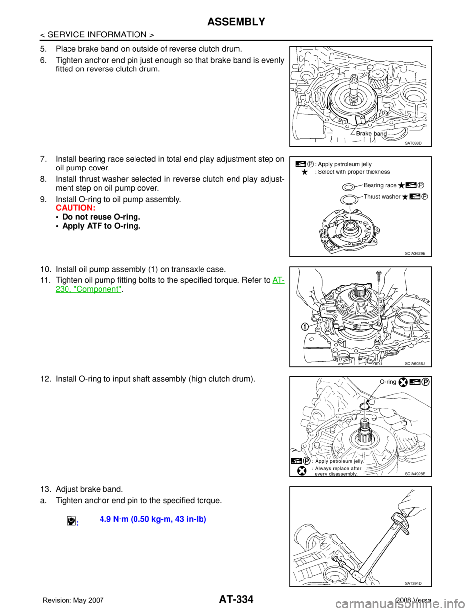
5. Place brake band on outside of reverse clutch drum.
6. Tighten anchor end pin just enough so that brake band is evenly
fitted on reverse clutch drum.
7. Install bearing race selected in total end play adjustment step on
oil pump cover.
8. Install thrust washer selected in reverse clutch end play adjust-
ment step on oil pump cover.
9. Install O-ring to oil pump assembly.
CAUTION:
• Do not reuse O-ring.
• Apply ATF to O-ring.
10. Install oil pump assembly (1) on transaxle case.
11. Tighten oil pump fitting bolts to the specified torque. Refer to AT-
230, "Component".
12. Install O-ring to input shaft assembly (high clutch drum).
13. Adjust brake band.
a. Tighten anchor end pin to the specified torque.
SAT038D
SCIA3629E
SCIA6036J
SCIA4928E
:4.9 N·m (0.50 kg-m, 43 in-lb)
SAT394D
Page 353 of 2771

SERVICE DATA AND SPECIFICATIONS (SDS)
AT-341
< SERVICE INFORMATION >
D
E
F
G
H
I
J
K
L
MA
B
AT
N
O
P
SERVICE DATA AND SPECIFICATIONS (SDS)
General SpecificationINFOID:0000000001703396
*: Refer to MA-10.
Vehicle Speed at Which Gear Shifting OccursINFOID:0000000001703397
• At half throttle, the accelerator opening is 4/8 of the full opening.
Vehicle Speed at When Lock-up Occurs/ReleasesINFOID:0000000001703398
Stall SpeedINFOID:0000000001703399
Line PressureINFOID:0000000001703400
Adjusting shims, Needle Bearings, Thrust Washers and Snap RingsINFOID:0000000001703401
NOTE:
EngineMR18DE
Automatic transaxle model RE4F03B
Automatic transaxle assembly Model code number 3CX0D
Transaxle gear ratio1st 2.861
2nd 1.562
3rd 1.000
4th 0.697
Reverse 2.310
Final drive 4.072
Recommended fluidGenuine NISSAN Matic D ATF (Continental U.S. and Alaska) or
Canada NISSAN Automatic Transmission Fluid*
Fluid capacity [ (US qt, Imp qt)]7.9 (8-3/8, 7)
Throttle positionVehicle speed km/h (MPH)
D1 → D2D2 → D3D3 → D4D4 → D3D3 → D2D2 → D1
Full throttle51 - 59
(32 - 37)97 - 105
(60 - 65)154 - 162
(96 - 101)150 - 158
(93 - 98)87 - 95
(54 - 59)40 - 48
(25 - 30)
Half throttle34 - 42
(21 - 26)62 - 70
(39 - 43)124 - 132
(77 - 82)69 - 77
(43 - 48)36 - 44
(22 - 27)19 - 27
(12 - 17)
Throttle position Selector lever positionVehicle speed km/h (MPH)
Lock-up ON Lock-up OFF
2.0/8“D” position 86 - 94 (53 - 58) 59 - 67 (37 - 42)
“D” position (OD OFF) 86 - 94 (53 - 58) 83 - 91 (52 - 57)
Stall revolution (rpm)2,310 - 2,770
Engine speedLine pressure kPa (kg/cm2, psi)
“D”, “2” and “1” positions “R” position
Idle speed 500 (5.1, 73) 778 (7.9, 113)
Stall speed 1,173 (12.0, 170) 1,825 (18.6, 265)
Page 354 of 2771
AT-342
< SERVICE INFORMATION >
SERVICE DATA AND SPECIFICATIONS (SDS)
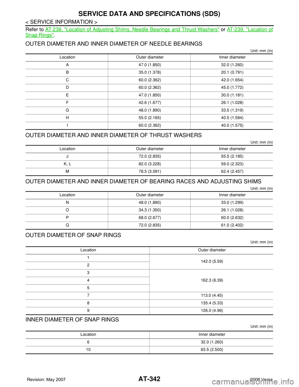
Refer to AT-238, "Location of Adjusting Shims, Needle Bearings and Thrust Washers" or AT-239, "Location of
Snap Rings".
OUTER DIAMETER AND INNER DIAMETER OF NEEDLE BEARINGS
Unit: mm (in)
OUTER DIAMETER AND INNER DIAMETER OF THRUST WASHERS
Unit: mm (in)
OUTER DIAMETER AND INNER DIAMETER OF BEARING RACES AND ADJUSTING SHIMS
Unit: mm (in)
OUTER DIAMETER OF SNAP RINGS
Unit: mm (in)
INNER DIAMETER OF SNAP RINGS
Unit: mm (in)
Location Outer diameter Inner diameter
A 47.0 (1.850) 32.0 (1.260)
B 35.0 (1.378) 20.1 (0.791)
C 60.0 (2.362) 42.0 (1.654)
D 60.0 (2.362) 45.0 (1.772)
E 47.0 (1.850) 30.0 (1.181)
F 42.6 (1.677) 26.1 (1.028)
G 48.0 (1.890) 33.5 (1.319)
H 55.0 (2.165) 40.5 (1.594)
I 60.0 (2.362) 40.0 (1.575)
Location Outer diameter Inner diameter
J 72.0 (2.835) 55.5 (2.185)
K, L 82.0 (3.228) 59.0 (2.323)
M 78.5 (3.091) 62.4 (2.457)
Location Outer diameter Inner diameter
N 48.0 (1.890) 33.0 (1.299)
O 34.3 (1.350) 26.1 (1.028)
P 68.0 (2.677) 60.0 (2.632)
Q 72.0 (2.835) 61.0 (2.402)
Location Outer diameter
1
142.0 (5.59)
2
3
162.3 (6.39) 4
5
7 113.0 (4.45)
8 135.4 (5.33)
9 126.0 (4.96)
Location Inner diameter
6 32.0 (1.260)
10 63.5 (2.500)
Page 357 of 2771
SERVICE DATA AND SPECIFICATIONS (SDS)
AT-345
< SERVICE INFORMATION >
D
E
F
G
H
I
J
K
L
MA
B
AT
N
O
P
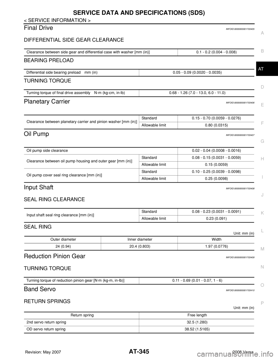
Final DriveINFOID:0000000001703405
DIFFERENTIAL SIDE GEAR CLEARANCE
BEARING PRELOAD
TURNING TORQUE
Planetary CarrierINFOID:0000000001703406
Oil PumpINFOID:0000000001703407
Input ShaftINFOID:0000000001703408
SEAL RING CLEARANCE
SEAL RING
Unit: mm (in)
Reduction Pinion GearINFOID:0000000001703409
TURNING TORQUE
Band ServoINFOID:0000000001703410
RETURN SPRINGS
Unit: mm (in)
Clearance between side gear and differential case with washer [mm (in)] 0.1 - 0.2 (0.004 - 0.008)
Differential side bearing preload mm (in) 0.05 - 0.09 (0.0020 - 0.0035)
Turning torque of final drive assembly N-m (kg-cm, in-lb) 0.68 - 1.26 (7.0 - 13.0, 6.0 - 11.0)
Clearance between planetary carrier and pinion washer [mm (in)]Standard 0.15 - 0.70 (0.0059 - 0.0276)
Allowable limit 0.80 (0.0315)
Oil pump side clearance0.02 - 0.04 (0.0008 - 0.0016)
Clearance between oil pump housing and outer gear [mm (in)]Standard 0.08 - 0.15 (0.0031 - 0.0059)
Allowable limit 0.15 (0.0059)
Oil pump cover seal ring clearance [mm (in)]Standard 0.10 - 0.25 (0.0039 - 0.0098)
Allowable limit 0.25 (0.0098)
Input shaft seal ring clearance [mm (in)]Standard 0.08 - 0.23 (0.0031 - 0.0091)
Allowable limit 0.23 (0.091)
Outer diameter Inner diameter Width
24 (0.94) 20.4 (0.803) 1.97 (0.0776)
Turning torque of reduction pinion gear [N·m (kg-m, in-lb)] 0.11 - 0.69 (0.01 - 0.07, 1 - 6)
Return spring Free length
2nd servo return spring 32.5 (1.280)
OD servo return spring 38.52 (1.5165)
Page 419 of 2771
BCM (BODY CONTROL MODULE)
BCS-3
< SERVICE INFORMATION >
C
D
E
F
G
H
I
J
L
MA
B
BCS
N
O
P
BCM (BODY CONTROL MODULE)
System DescriptionINFOID:0000000001704584
BCM (body control module) controls the operation of various electrical units installed on the vehicle.
BCM FUNCTION
BCM has a combination switch reading function for reading the operation of combination switches (light, wiper,
washer, turn signal) in addition to the function for controlling the operation of various electrical components.
Also, it functions as an interface that receives signals from the front air control, and sends signals to ECM
using CAN communication.
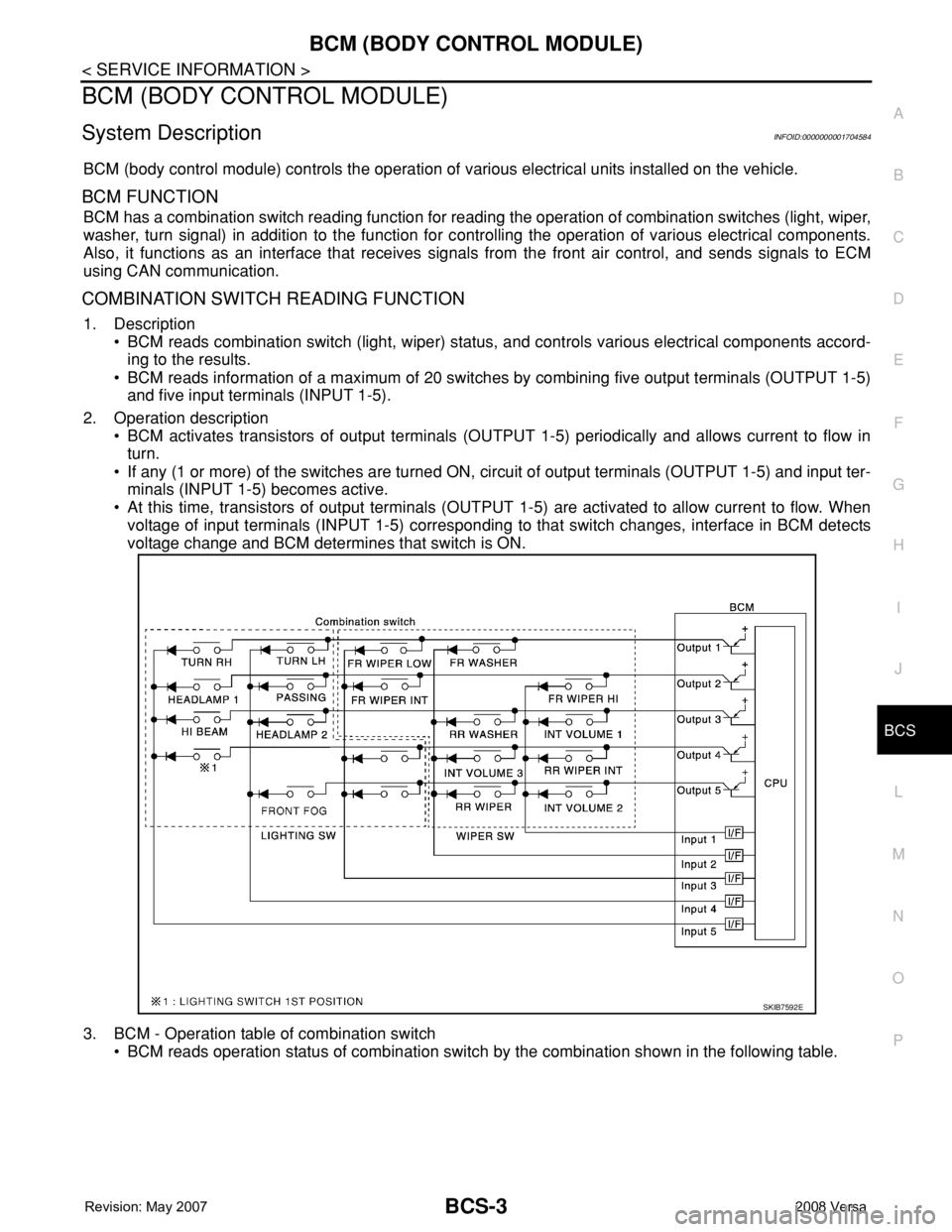
COMBINATION SWITCH READING FUNCTION
1. Description
• BCM reads combination switch (light, wiper) status, and controls various electrical components accord-
ing to the results.
• BCM reads information of a maximum of 20 switches by combining five output terminals (OUTPUT 1-5)
and five input terminals (INPUT 1-5).
2. Operation description
• BCM activates transistors of output terminals (OUTPUT 1-5) periodically and allows current to flow in
turn.
• If any (1 or more) of the switches are turned ON, circuit of output terminals (OUTPUT 1-5) and input ter-
minals (INPUT 1-5) becomes active.
• At this time, transistors of output terminals (OUTPUT 1-5) are activated to allow current to flow. When
voltage of input terminals (INPUT 1-5) corresponding to that switch changes, interface in BCM detects
voltage change and BCM determines that switch is ON.
3. BCM - Operation table of combination switch
• BCM reads operation status of combination switch by the combination shown in the following table.
SKIB7592E
Page 422 of 2771
BCS-6
< SERVICE INFORMATION >
BCM (BODY CONTROL MODULE)
• When CAN communication operation is detected, it switches to CAN communication status.
• When a state of the following switches changes, it switches to CAN communication state:
- Ignition switch
- Key switch (without Intelligent Key)
- Key switch and ignition knob switch (with Intelligent Key)
- Hazard switch
- Door lock/unlock switch
- Front door switch (LH, RH)
- Rear door switch (LH, RH)
- Back door lock assembly (Hatchback)
- Trunk key cylinder switch (Sedan)
- Trunk lamp switch and trunk release solenoid (Sedan)
- Combination switch (passing, lighting switch 1st position, front fog lamp)
- Keyfob (lock/unlock signal)
- Front door key cylinder switch LH
• When control performed only by BCM is required by switch, it shifts to CAN communication inactive
mode.
• Status of combination switch reading function is changed.
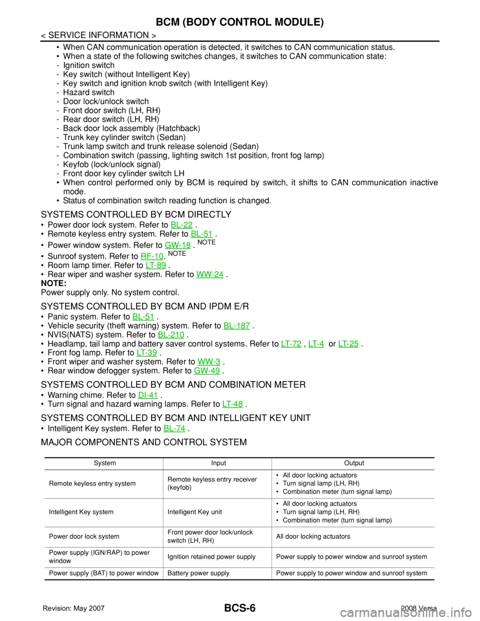
SYSTEMS CONTROLLED BY BCM DIRECTLY
• Power door lock system. Refer to BL-22 .
• Remote keyless entry system. Refer to BL-51
.
• Power window system. Refer to GW-18
. NOTE
• Sunroof system. Refer to RF-10. NOTE
• Room lamp timer. Refer to LT- 8 9 .
• Rear wiper and washer system. Refer to WW-24
.
NOTE:
Power supply only. No system control.
SYSTEMS CONTROLLED BY BCM AND IPDM E/R
• Panic system. Refer to BL-51 .
• Vehicle security (theft warning) system. Refer to BL-187
.
• NVIS(NATS) system. Refer to BL-210
.
• Headlamp, tail lamp and battery saver control systems. Refer to LT- 7 2
, LT- 4 or LT- 2 5 .
• Front fog lamp. Refer to LT- 3 9
.
• Front wiper and washer system. Refer to WW-3
.
• Rear window defogger system. Refer to GW-49
.
SYSTEMS CONTROLLED BY BCM AND COMBINATION METER
• Warning chime. Refer to DI-41 .
• Turn signal and hazard warning lamps. Refer to LT- 4 8
.
SYSTEMS CONTROLLED BY BCM AND INTELLIGENT KEY UNIT
• Intelligent Key system. Refer to BL-74 .
MAJOR COMPONENTS AND CONTROL SYSTEM
System Input Output
Remote keyless entry systemRemote keyless entry receiver
(keyfob)• All door locking actuators
• Turn signal lamp (LH, RH)
• Combination meter (turn signal lamp)
Intelligent Key system Intelligent Key unit• All door locking actuators
• Turn signal lamp (LH, RH)
• Combination meter (turn signal lamp)
Power door lock systemFront power door lock/unlock
switch (LH, RH)All door locking actuators
Power supply (IGN/RAP) to power
windowIgnition retained power supply Power supply to power window and sunroof system
Power supply (BAT) to power window Battery power supply Power supply to power window and sunroof system
Page 423 of 2771
BCM (BODY CONTROL MODULE)
BCS-7
< SERVICE INFORMATION >
C
D
E
F
G
H
I
J
L
MA
B
BCS
N
O
P
CAN Communication System DescriptionINFOID:0000000001704585
Refer to LAN-6, "System Description".
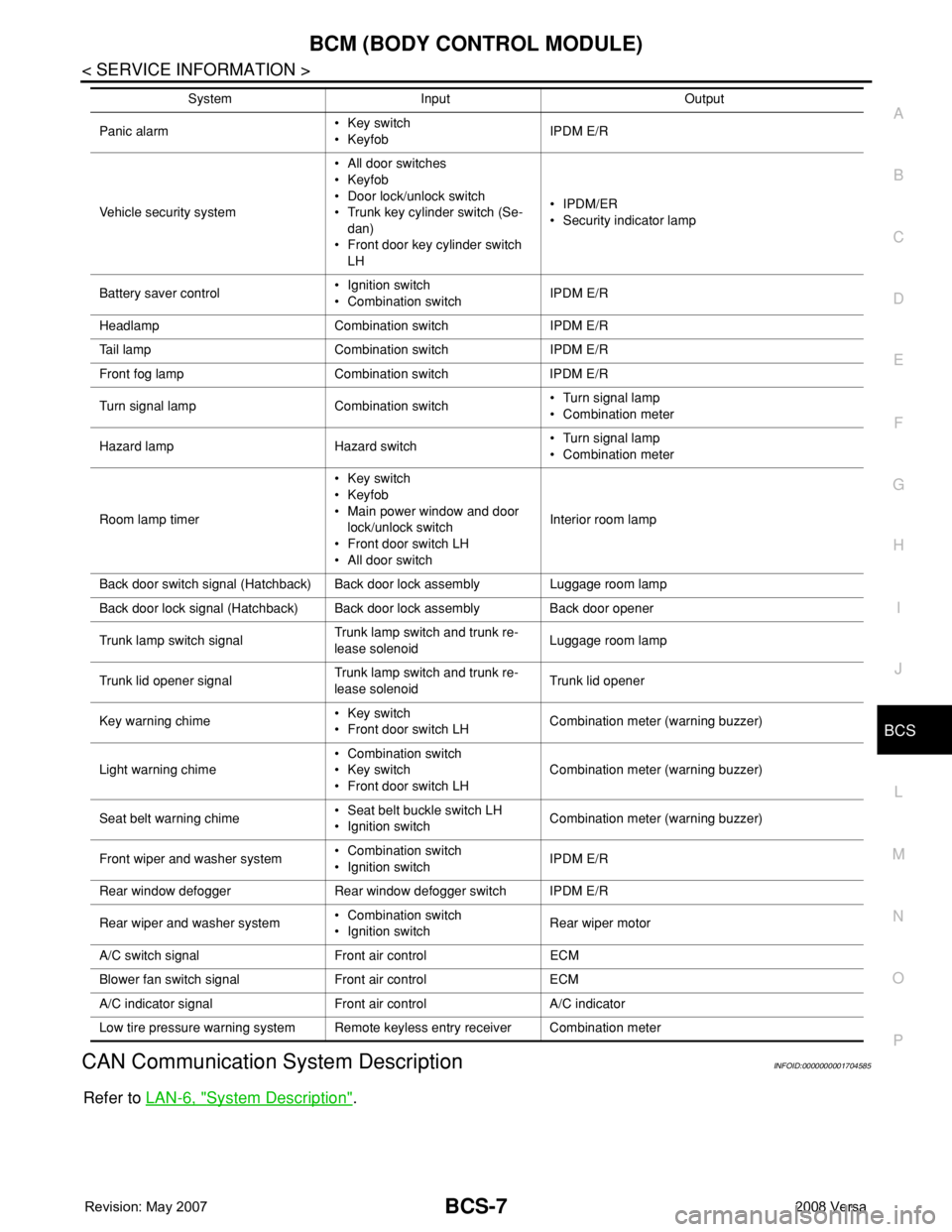
Panic alarm• Key switch
•KeyfobIPDM E/R
Vehicle security system• All door switches
•Keyfob
• Door lock/unlock switch
• Trunk key cylinder switch (Se-
dan)
• Front door key cylinder switch
LH• IPDM/ER
• Security indicator lamp
Battery saver control• Ignition switch
• Combination switchIPDM E/R
Headlamp Combination switch IPDM E/R
Tail lamp Combination switch IPDM E/R
Front fog lamp Combination switch IPDM E/R
Turn signal lamp Combination switch• Turn signal lamp
• Combination meter
Hazard lamp Hazard switch• Turn signal lamp
• Combination meter
Room lamp timer• Key switch
•Keyfob
• Main power window and door
lock/unlock switch
• Front door switch LH
• All door switchInterior room lamp
Back door switch signal (Hatchback) Back door lock assembly Luggage room lamp
Back door lock signal (Hatchback) Back door lock assembly Back door opener
Trunk lamp switch signalTrunk lamp switch and trunk re-
lease solenoidLuggage room lamp
Trunk lid opener signalTrunk lamp switch and trunk re-
lease solenoidTrunk lid opener
Key warning chime• Key switch
• Front door switch LHCombination meter (warning buzzer)
Light warning chime• Combination switch
• Key switch
• Front door switch LHCombination meter (warning buzzer)
Seat belt warning chime• Seat belt buckle switch LH
• Ignition switchCombination meter (warning buzzer)
Front wiper and washer system• Combination switch
• Ignition switchIPDM E/R
Rear window defogger Rear window defogger switch IPDM E/R
Rear wiper and washer system• Combination switch
• Ignition switchRear wiper motor
A/C switch signal Front air control ECM
Blower fan switch signal Front air control ECM
A/C indicator signal Front air control A/C indicator
Low tire pressure warning system Remote keyless entry receiver Combination meterSystem Input Output
Page 453 of 2771

RADIATOR CORE SUPPORT
BL-19
< SERVICE INFORMATION >
C
D
E
F
G
H
J
K
L
MA
B
BL
N
O
P
RADIATOR CORE SUPPORT
Removal and InstallationINFOID:0000000001703951
REMOVAL
Radiator Core Support Upper
1. Remove the air duct. Refer to EM-16, "Removal and Installation" .
2. Remove the headlamp (LH/RH). Refer to LT-23, "
Removal and Installation" .
3. Remove the hood lock assembly, and remove hood lock cable. Refer to BL-15
.
4. Remove the air guide and hood lock cable clip.
5. Remove the washer tank inlet. Refer to WW-22, "
Removal and Installation of Washer Tank" .
6. Remove the radiator core support upper.
Radiator Core Support Lower
1. Remove the air duct. Refer to EM-16, "Removal and Installation" .
2. Remove the front bumper. Refer to EI-14, "
Removal and Installation" .
3. Remove the headlamp (LH/RH). Refer to LT-23, "
Removal and Installation" .
4. Remove the hood lock assembly, and remove hood lock cable. Refer to BL-15
.
5. Remove the air guide and hood lock cable mounting clip.
6. Remove the front bumper reinforcement. Refer to EI-14, "
Removal and Installation" .
7. Remove the radiator core lower stay.
8. Remove the undercover.
PIIB6515E
1. Radiator core support upper 2. Radiator core support lower 3. Radiator core support lower stay
4. Radiator core support side stay 5. Air guide
24.5 N·m (2.5 kg-m, 18 ft-lb)
Page 583 of 2771
DOOR
BL-149
< SERVICE INFORMATION >
C
D
E
F
G
H
J
K
L
MA
B
BL
N
O
P
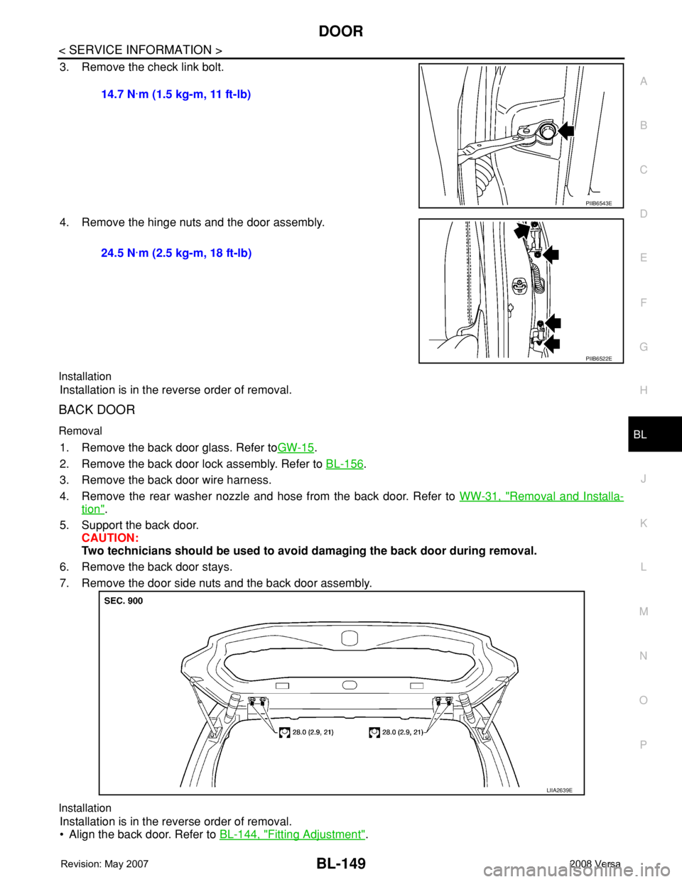
3. Remove the check link bolt.
4. Remove the hinge nuts and the door assembly.
Installation
Installation is in the reverse order of removal.
BACK DOOR
Removal
1. Remove the back door glass. Refer toGW-15.
2. Remove the back door lock assembly. Refer to BL-156
.
3. Remove the back door wire harness.
4. Remove the rear washer nozzle and hose from the back door. Refer to WW-31, "
Removal and Installa-
tion".
5. Support the back door.
CAUTION:
Two technicians should be used to avoid damaging the back door during removal.
6. Remove the back door stays.
7. Remove the door side nuts and the back door assembly.
Installation
Installation is in the reverse order of removal.
• Align the back door. Refer to BL-144, "
Fitting Adjustment". 14.7 N·m (1.5 kg-m, 11 ft-lb)
PIIB6543E
24.5 N·m (2.5 kg-m, 18 ft-lb)
PIIB6522E
LIIA2639E
Page 742 of 2771

BRAKE TUBE AND HOSE
BR-11
< SERVICE INFORMATION >
C
D
E
G
H
I
J
K
L
MA
B
BR
N
O
P
1. Drain brake fluid. Refer to BR-8, "Drain and Refill" .
2. Using a flare nut wrench, remove brake tube from brake hose.
3. Remove union bolt, and remove brake hose from caliper assem-
bly.
4. Remove lock plate, and remove brake hose from vehicle.
INSTALLATION
1. Assemble union bolt and copper washers to brake hose.
2. Position the L-shape metal fitting of the brake hose to the brake
caliper assembly positioning hole.
3. Tighten union bolt to the specified torque. Refer to BR-10,
"Hydraulic Circuit" .
4. Connect brake hose to brake tube on vehicle, and temporarily
tighten flare nut by hand as much as possible.
5. Secure it with lock plate.
6. Tighten flare nut to the specified torque with a flare nut torque
wrench. Refer to BR-10, "
Hydraulic Circuit" .
7. Install brake hose to vehicle, and tighten nuts to the specified
torque.
8. Bleed air from brake system. Refer to BR-8, "
Bleeding Brake System" .
Rear Brake Tube and HoseINFOID:0000000001703786
REMOVAL
1. Drain brake fluid. Refer to BR-8, "Drain and Refill" .
2. Using a flare nut wrench, remove brake tube from brake hose.
3. Remove lock plate, and remove brake hose from vehicle.
INSTALLATION
1. Connect brake hose to brake tube on vehicle, and temporarily tighten flare nut by hand as much as possi-
ble.
2. Secure it to bracket with lock plate.
3. Tighten flare nut to the specified torque with a flare nut torque wrench. Refer to BR-10, "
Hydraulic Circuit"
.
4. Bleed air from brake system. Refer to BR-8, "
Bleeding Brake System" .
Inspection After InstallationINFOID:0000000001703787
CAUTION:
• Always disassemble the parts and retighten their fittings, if a brake fluid leak is detected. Replace
applicable part with a new one, if damaged part is detected.
• If leak is detected at the connections, retighten it or replace the damaged part.
S F I A 111 8 E
SFIA1137E
SFIA1120E