Ipdm NISSAN TIIDA 2008 Service Service Manual
[x] Cancel search | Manufacturer: NISSAN, Model Year: 2008, Model line: TIIDA, Model: NISSAN TIIDA 2008Pages: 2771, PDF Size: 60.61 MB
Page 1385 of 2771

DTC P0420 THREE WAY CATALYST FUNCTION
EC-311
< SERVICE INFORMATION >
C
D
E
F
G
H
I
J
K
L
MA
EC
N
P O
OK >> GO TO 6.
NG >> Perform EC-523, "
Diagnosis Procedure".
6.CHECK FUNCTION OF IGNITION COIL-I
CAUTION:
Do the following procedure in the place where ventilation is good without the combustible.
1. Turn ignition switch OFF.
2. Remove fuel pump (1) fuse in IPDM E/R (2) to release fuel pres-
sure.
NOTE:
Do not use CONSULT-II to release fuel pressure, or fuel pres-
sure applies again during the following procedure.
- : Vehicle front
3. Start engine.
4. After engine stalls, crank it two or three times to release all fuel
pressure.
5. Turn ignition switch OFF.
6. Remove all ignition coil harness connectors to avoid the electri-
cal discharge from the ignition coils.
7. Remove ignition coil and spark plug of the cylinder to be checked.
8. Crank engine for 5 seconds or more to remove combustion gas in the cylinder.
9. Connect spark plug and harness connector to ignition coil.
10. Fix ignition coil using a rope etc. with gap of 13 - 17 mm
between the edge of the spark plug and grounded metal portion
as shown in the figure.
11. Crank engine for about 3 seconds, and check whether spark is
generated between the spark plug and the grounded metal por-
tion.
CAUTION:
• Do not approach to the spark plug and the ignition coil
within 50cm. Be careful not to get an electrical shock
while checking, because the electrical discharge voltage
becomes 20kV or more.
• It might cause to damage the ignition coil if the gap of more than 17 mm is taken.
NOTE:
When the gap is less than 13 mm, the spark might be generated even if the coil is malfunctioning.
OK or NG
OK >> GO TO 10.
NG >> GO TO 7.
7.CHECK FUNCTION OF IGNITION COIL-II
1. Turn ignition switch OFF.
2. Disconnect spark plug and connect a known-good spark plug.
3. Crank engine for about 3 seconds, and recheck whether spark is generated between the spark plug and
the grounded metal portion.
OK or NG
OK >> GO TO 8.
NG >> Check ignition coil, power transistor and their circuits. Refer to EC-531
.
8.CHECK SPARK PLUGSpark should be generated.
PBIB2958E
PBIB2325E
Spark should be generated.
Page 1403 of 2771

DTC P0443 EVAP CANISTER PURGE VOLUME CONTROL SOLENOID VALVE
EC-329
< SERVICE INFORMATION >
C
D
E
F
G
H
I
J
K
L
MA
EC
N
P O
4. Check voltage between EVAP canister purge volume control
solenoid valve terminal 1 and ground with CONSULT-II or tester.
OK or NG
OK >> GO TO 3.
NG >> GO TO 2.
2.DETECT MALFUNCTIONING PART
Check the following.
• Harness connectors E8, F8
• Harness for open or short between EVAP canister purge volume control solenoid valve and IPDM E/R
>> Repair open circuit or short to ground or short to power in harness or connectors.
3.CHECK EVAP CANISTER PURGE VOLUME CONTROL SOLENOID VALVE OUTPUT SIGNAL CIRCUIT
FOR OPEN AND SHORT
1. Turn ignition switch OFF.
2. Disconnect ECM harness connector.
3. Check harness continuity between ECM terminal 9 and EVAP canister purge volume control solenoid
valve terminal 2. Refer to Wiring Diagram.
4. Also check harness for short to ground and short to power.
OK or NG
OK >> GO TO 4.
NG >> Repair open circuit or short to ground or short to power in harness or connectors.
4.CHECK EVAP CONTROL SYSTEM PRESSURE SENSOR CONNECTOR
1. Disconnect EVAP control system pressure sensor harness con-
nector.
- EVAP control system pressure sensor (1)
- EVAP canister (2)
- EVAP canister vent control valve (3)
2. Check connectors for water.
OK or NG
OK >> GO TO 5.
NG >> Replace EVAP control system pressure sensor.
5.CHECK EVAP CONTROL SYSTEM PRESSURE SENSOR
Refer to EC-361, "
Component Inspection".
OK or NG
OK (With CONSULT-II)>>GO TO 6.
OK (Without CONSULT-II)>>GO TO 7.
NG >> Replace EVAP control system pressure sensor.
6.CHECK EVAP CANISTER PURGE VOLUME CONTROL SOLENOID VALVE
With CONSULT-II
1. Turn ignition switch OFF.
2. Reconnect harness connectors disconnected.
3. Start engine.Voltage: Battery voltage
PBIB0080E
Continuity should exist.
Water should not exist.
BBIA0693E
Page 1410 of 2771

EC-336
< SERVICE INFORMATION >
DTC P0444, P0445 EVAP CANISTER PURGE VOLUME CONTROL SOLENOID
VALVE
4. Check voltage between EVAP canister purge volume control
solenoid valve terminal 1 and ground with CONSULT-II or tester.
OK or NG
OK >> GO TO 3.
NG >> GO TO 2.
2.DETECT MALFUNCTIONING PART
Check the following.
• Harness connectors E8, F8
• Harness for open or short between EVAP canister purge volume control solenoid valve and IPDM E/R
>> Repair open circuit or short to ground or short to power in harness or connectors.
3.CHECK EVAP CANISTER PURGE VOLUME CONTROL SOLENOID VALVE OUTPUT SIGNAL CIRCUIT
FOR OPEN AND SHORT
1. Turn ignition switch OFF.
2. Disconnect ECM harness connector.
3. Check harness continuity between ECM terminal 9 and EVAP canister purge volume control solenoid
valve terminal 2. Refer to Wiring Diagram.
4. Also check harness for short to ground and short to power.
OK or NG
OK (With CONSULT-II)>>GO TO 4.
OK (Without CONSULT-II)>>GO TO 5.
NG >> Repair open circuit or short to ground or short to power in harness or connectors.
4.CHECK EVAP CANISTER PURGE VOLUME CONTROL SOLENOID VALVE OPERATION
With CONSULT-II
1. Reconnect all harness connectors disconnected.
2. Start engine.
3. Perform “PURG VOL CONT/V” in “ACTIVE TEST” mode with
CONSULT-II. Check that engine speed varies according to the
valve opening.
OK or NG
OK >> GO TO 6.
NG >> GO TO 5.
5.CHECK EVAP CANISTER PURGE VOLUME CONTROL SOLENOID VALVE
Refer to EC-337, "
Component Inspection".
OK or NG
OK >> GO TO 6.
NG >> Replace EVAP canister purge volume control solenoid valve.
6.CHECK INTERMITTENT INCIDENT
Refer to EC-136
. Voltage: Battery voltage
SEF206W
Continuity should exist.
PBIB1786E
Page 1416 of 2771

EC-342
< SERVICE INFORMATION >
DTC P0447 EVAP CANISTER VENT CONTROL VALVE
4. Check voltage between EVAP canister vent control valve termi-
nal 1 and ground with CONSULT-II or tester.
OK or NG
OK >> GO TO 5.
NG >> GO TO 4.
4.DETECT MALFUNCTIONING PART
Check the following.
• Harness connectors E8, F8
• Harness connectors E7, B69
• Harness connectors M12, B101
• Harness for open or short between EVAP canister vent control valve and IPDM E/R
>> Repair open circuit or short to ground or short to power in harness or connectors.
5.CHECK EVAP CANISTER VENT CONTROL VALVE OUTPUT SIGNAL CIRCUIT FOR OPEN AND SHORT
1. Turn ignition switch OFF.
2. Disconnect ECM harness connector.
3. Check harness continuity between ECM terminal 28 and EVAP canister vent control valve terminal 2.
Refer to Wiring Diagram.
4. Also check harness for short to ground and short to power.
OK or NG
OK >> GO TO 7.
NG >> GO TO 6.
6.DETECT MALFUNCTIONING PART
Check the following.
• Harness connectors E8, F8
• Harness connectors E7, B69
• Harness connectors M13, B102
• Harness for open or short between EVAP canister vent control valve and ECM
>> Repair open circuit or short to ground or short to power in harness or connectors.
7.CHECK RUBBER TUBE FOR CLOGGING
1. Disconnect rubber tube connected to EVAP canister vent control valve.
2. Check the rubber tube for clogging.
OK or NG
OK >> GO TO 8.
NG >> Clean the rubber tube using an air blower.
8.CHECK EVAP CANISTER VENT CONTROL VALVE
Refer to EC-343, "
Component Inspection".
OK or NG
OK >> GO TO 9.
NG >> Replace EVAP canister vent control valve.
9.CHECK INTERMITTENT INCIDENT
Refer to EC-136
. Voltage: Battery voltage
PBIB0080E
Continuity should exist.
Page 1486 of 2771

EC-412
< SERVICE INFORMATION >
DTC P1217 ENGINE OVER TEMPERATURE
DTC P1217 ENGINE OVER TEMPERATURE
System DescriptionINFOID:0000000001702929
SYSTEM DESCRIPTION
NOTE:
•If DTC P1217 is displayed with DTC U1000 or U1001, first perform the trouble diagnosis for DTC
U1000, U1001. Refer to EC-143
.
•If DTC P1217 is displayed with DTC U1010, first perform the trouble diagnosis for DTC U1010. Refer
to EC-145
.
Cooling Fan Control
*1: The ECM determines the start signal status by the signals of engine speed and battery voltage.
*2: This signal is sent to ECM through CAN communication line.
The ECM controls the cooling fan corresponding to the vehicle speed, engine coolant temperature, refrigerant
pressure, and air conditioner ON signal. The control system has 3-step control [HIGH/LOW/OFF].
Cooling Fan Operation
Models with A/C
Models without A/C
Sensor Input Signal to ECM ECM function Actuator
Crankshaft position sensor (POS)
Camshaft position sensor (PHASE)Engine speed*
1
Cooling fan
controlIPDM E/R
(Cooling fan relays) Battery
Battery voltage*
1
Wheel sensor
Vehicle speed*2
Engine coolant temperature sensor Engine coolant temperature
Air conditioner switch
Air conditioner ON signal*
2
Refrigerant pressure sensor Refrigerant pressure
PBIB2483E
PBIB3335E
Page 1487 of 2771

DTC P1217 ENGINE OVER TEMPERATURE
EC-413
< SERVICE INFORMATION >
C
D
E
F
G
H
I
J
K
L
MA
EC
N
P O Cooling Fan Relay Operation
The ECM controls cooling fan relays in the IPDM E/R through CAN communication line.
CONSULT-II Reference Value in Data Monitor ModeINFOID:0000000001702930
Specification data are reference values.
On Board Diagnosis LogicINFOID:0000000001702931
If the cooling fan or another component in the cooling system malfunctions, engine coolant temperature will
rise. When the engine coolant temperature reaches an abnormally high temperature condition, a malfunction
is indicated.
This self-diagnosis has the one trip detection logic.
CAUTION:
When a malfunction is indicated, be sure to replace the coolant. Refer to CO-8, "
Changing Engine
Coolant". Also, replace the engine oil. Refer to LU-7, "Changing Engine Oil".
1. Fill radiator with coolant up to specified level with a filling speed of 2 liters per minute. Be sure to
use coolant with the proper mixture ratio. Refer to MA-11, "
Anti-freeze Coolant Mixture Ratio".
2. After refilling coolant, run engine to ensure that no water-flow noise is emitted.
Overall Function CheckINFOID:0000000001702932
Use this procedure to check the overall function of the cooling fan. During this check, a DTC might not be con-
firmed.
WARNING:
Cooling fan speedCooling fan relay
123
Stop (OFF) OFF OFF OFF
Low (LOW) ON OFF OFF
High (HI) OFF ON ON
MONITOR ITEM CONDITION SPECIFICATION
AIR COND SIG• Engine: After warming up, idle
the engineAir conditioner switch: OFF OFF
Air conditioner switch: ON
(Compressor operates.)ON
COOLING FAN• Engine: After warming up, idle
the engine
• Air conditioner switch: OFFEngine coolant temperature: 97°C
(207°F) or lessOFF
Engine coolant temperature: Between
98°C (208°F) and 99°C (210°F) or
moreLOW
Engine coolant temperature: 100°C
(212°F) or moreHIGH
DTC No. Trouble diagnosis name DTC detecting condition Possible cause
P1217
1217Engine over temperature
(Overheat)• Cooling fan does not operate properly (Over-
heat).
• Cooling fan system does not operate properly
(Overheat).
• Engine coolant was not added to the system
using the proper filling method.
• Engine coolant is not within the specified
range.• Harness or connectors
(Cooling fan circuit is open or shorted.)
• Cooling fan
• IPDM E/R (Cooling fan relays)
•Radiator hose
•Radiator
• Reservoir tank
•Radiator cap
• Water pump
•Thermostat
• Water control valve
For more information, refer to EC-424,
"Main 13 Causes of Overheating".
Page 1489 of 2771
DTC P1217 ENGINE OVER TEMPERATURE
EC-415
< SERVICE INFORMATION >
C
D
E
F
G
H
I
J
K
L
MA
EC
N
P O
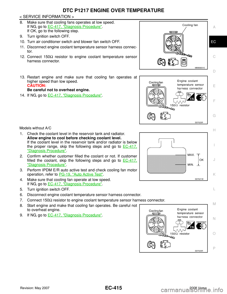
8. Make sure that cooling fans operates at low speed.
If NG, go to EC-417, "
Diagnosis Procedure".
If OK, go to the following step.
9. Turn ignition switch OFF.
10. Turn air conditioner switch and blower fan switch OFF.
11. Disconnect engine coolant temperature sensor harness connec-
tor.
12. Connect 150Ω resistor to engine coolant temperature sensor
harness connector.
13. Restart engine and make sure that cooling fan operates at
higher speed than low speed.
CAUTION:
Be careful not to overheat engine.
14. If NG, go to EC-417, "
Diagnosis Procedure".
Models without A/C
1. Check the coolant level in the reservoir tank and radiator.
Allow engine to cool before checking coolant level.
If the coolant level in the reservoir tank and/or radiator is below
the proper range, skip the following steps and go to EC-417,
"Diagnosis Procedure".
2. Confirm whether customer filled the coolant or not. If customer
filled the coolant, skip the following steps and go to EC-417,
"Diagnosis Procedure".
3. Perform IPDM E/R auto active test and check cooling fan motor
operation, refer to PG-19, "
Auto Active Test".
4. Make sure that cooling fan operate at low speed.
If NG, go to EC-417, "
Diagnosis Procedure".
5. Turn ignition switch OFF.
6. Disconnect engine coolant temperature sensor harness connector.
7. Connect 150Ω resistor to engine coolant temperature sensor harness connector.
8. Start engine and make that cooling fan operates. Be careful not
to overheat engine.
9. If NG, go to EC-417, "
Diagnosis Procedure".
MBIB0651E
SEF023R
SEF621W
SEF023R
Page 1493 of 2771

DTC P1217 ENGINE OVER TEMPERATURE
EC-419
< SERVICE INFORMATION >
C
D
E
F
G
H
I
J
K
L
MA
EC
N
P O
5. Restart engine and make sure that cooling fan operate at higher
speed than low speed.
OK or NG
OK >> GO TO 6.
NG >> Check cooling fan high speed control circuit. (Go to
"PROCEDURE A".)
6.CHECK COOLING SYSTEM FOR LEAK
Refer to CO-8
.
OK or NG
OK >> GO TO 8.
NG >> GO TO 7.
7.DETECT MALFUNCTIONING PART
Check the following for leak.
•Hose
• Radiator
• Water pump (Refer to CO-16
.)
>> Repair or replace.
8.CHECK RADIATOR CAP
Refer to CO-11
.
OK or NG
OK >> GO TO 9.
NG >> Replace radiator cap.
9.CHECK COMPONENT PARTS
Check the following;.
• Thermostat. (Refer to CO-16
.)
• Water control valve. (Refer to CO-19
.)
• Engine coolant temperature sensor. (Refer to EC-191, "
Component Inspection".)
OK or NG
OK >> GO TO 10.
NG >> Replace malfunctioning component.
10.CHECK MAIN 13 CAUSES
If the cause cannot be isolated, go to EC-424, "
Main 13 Causes of Overheating".
>>INSPECTION END
PROCEDURE A
1.CHECK POWER SUPPLY CIRCUIT
1. Turn ignition switch OFF.
2. Disconnect IPDM E/R harness connector E44.
SEF023R
Page 1494 of 2771

EC-420
< SERVICE INFORMATION >
DTC P1217 ENGINE OVER TEMPERATURE
3. Check voltage between IPDM E/R terminal 22 and ground with
CONSULT-II or tester.
OK or NG
OK >> GO TO 3.
NG >> GO TO 2.
2.DETECT MALFUNCTIONING PART
Check the following.
• 50A fusible link
• Harness for open or short between IPDM E/R and battery
>> Repair open circuit or short to ground or short to power in harness or connectors.
3.CHECK COOLING FAN MOTOR CIRCUIT
1. Disconnect cooling fan motor harness connector (1).
- : Vehicle front
-Resistor (2)
2. Disconnect IPDM E/R harness connectors E46 and E48.
3. Check harness continuity between the following;
cooling fan motor terminal 1 and IPDM E/R terminal 24,
cooling fan motor terminal 2 and ground.
Refer to wiring diagram.
4. Also check harness for short to ground and short to power.
5. Check harness continuity between IPDM E/R terminal 20 and
cooling fan motor terminal 1.
Refer to wiring diagram.
6. Also check harness for short to ground and short to power.
7. Check harness continuity between IPDM E/R terminals 39, 59 and ground.
Refer to Wiring Diagram.
8. Also check harness for short to ground and short to power.
OK or NG
OK >> GO TO 5.
NG >> GO TO 4.
4.DETECT MALFUNCTIONING PART
Check the following.
• Harness for open or short between cooling fan motor and IPDM E/R
• Harness for open or short between cooling fan motor and ground
•Resistor E5
>> Repair open circuit or short to ground or short to power in harness or connectors.
5.CHECK COOLING FAN MOTOR
Refer to EC-424, "
Component Inspection".
OK or NG
Voltage: Battery voltage
PBIB2607E
Continuity should exist.
Continuity should exist.
Continuity should exist.
BBIA0706E
Page 1495 of 2771

DTC P1217 ENGINE OVER TEMPERATURE
EC-421
< SERVICE INFORMATION >
C
D
E
F
G
H
I
J
K
L
MA
EC
N
P O
OK >> GO TO 6.
NG >> Replace cooling fan motor.
6.CHECK INTERMITTENT INCIDENT
Perform EC-136
.
OK or NG
OK >> Replace IPDM E/R. Refer to PG-26, "Removal and Installation of IPDM E/R".
NG >> Repair or replace harness or connector.
PROCEDURE FOR MODELS WITHOUT A/C
1.INSPECTION START
Do you have CONSULT-II?
Ye s o r N o
Yes >> GO TO 2.
No >> GO TO 4.
2.CHECK COOLING FAN LOW SPEED OPERATION
With CONSULT-II
1. Turn ignition switch ON.
2. Perform “COOLING FAN” in “ACTIVE TEST” mode with CON-
SULT-II and touch “LOW” on the CONSULT-II screen.
3. Make sure that cooling fan operate at low speed.
OK or NG
OK >> GO TO3.
NG >> Check cooling fan control circuit. (Go to "PROCEDURE
B".)
3.CHECK COOLING FAN HIGH SPEED OPERATION
With CONSULT-II
1. Touch “HIGH” on the CONSULT-II screen.
2. Make sure that cooling fan operates at higher speed than low
speed.
OK or NG
OK >> GO TO 6.
NG >> Check cooling fan control circuit. (Go to "PROCEDURE
A".)
4.CHECK COOLING FAN LOW SPEED OPERATION
Without CONSULT-II
1. Perform IPDM E/R auto active test and check cooling fan motor operation.
Refer to PG-19, "
Auto Active Test".
2. Make sure that cooling fan operate at low speed.
OK or NG
OK >> GO TO 5.
NG >> Check cooling fan speed control circuit. (Go to "PROCEDURE B".)
5.CHECK COOLING FAN HIGH SPEED OPERATION
Without CONSULT-II
1. Turn ignition switch OFF.
SEF784Z
SEF785Z