combination meter CAN NISSAN TIIDA 2008 Service Service Manual
[x] Cancel search | Manufacturer: NISSAN, Model Year: 2008, Model line: TIIDA, Model: NISSAN TIIDA 2008Pages: 2771, PDF Size: 60.61 MB
Page 1463 of 2771
DTC P0462, P0463 FUEL LEVEL SENSOR
EC-389
< SERVICE INFORMATION >
C
D
E
F
G
H
I
J
K
L
MA
EC
N
P O
DTC P0462, P0463 FUEL LEVEL SENSOR
Component DescriptionINFOID:0000000001702895
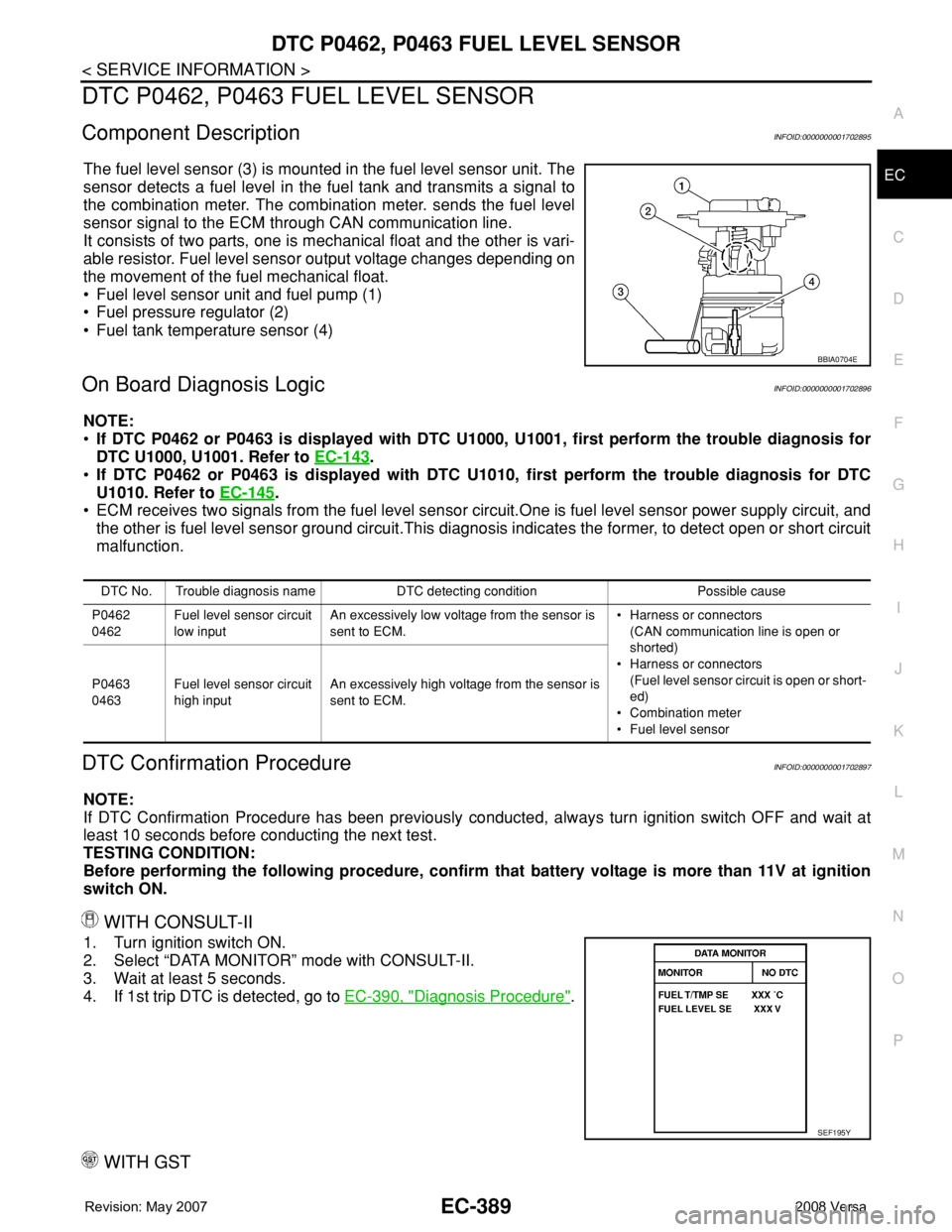
The fuel level sensor (3) is mounted in the fuel level sensor unit. The
sensor detects a fuel level in the fuel tank and transmits a signal to
the combination meter. The combination meter. sends the fuel level
sensor signal to the ECM through CAN communication line.
It consists of two parts, one is mechanical float and the other is vari-
able resistor. Fuel level sensor output voltage changes depending on
the movement of the fuel mechanical float.
• Fuel level sensor unit and fuel pump (1)
• Fuel pressure regulator (2)
• Fuel tank temperature sensor (4)
On Board Diagnosis LogicINFOID:0000000001702896
NOTE:
•If DTC P0462 or P0463 is displayed with DTC U1000, U1001, first perform the trouble diagnosis for
DTC U1000, U1001. Refer to EC-143
.
•If DTC P0462 or P0463 is displayed with DTC U1010, first perform the trouble diagnosis for DTC
U1010. Refer to EC-145
.
• ECM receives two signals from the fuel level sensor circuit.One is fuel level sensor power supply circuit, and
the other is fuel level sensor ground circuit.This diagnosis indicates the former, to detect open or short circuit
malfunction.
DTC Confirmation ProcedureINFOID:0000000001702897
NOTE:
If DTC Confirmation Procedure has been previously conducted, always turn ignition switch OFF and wait at
least 10 seconds before conducting the next test.
TESTING CONDITION:
Before performing the following procedure, confirm that battery voltage is more than 11V at ignition
switch ON.
WITH CONSULT-II
1. Turn ignition switch ON.
2. Select “DATA MONITOR” mode with CONSULT-II.
3. Wait at least 5 seconds.
4. If 1st trip DTC is detected, go to EC-390, "
Diagnosis Procedure".
WITH GST
BBIA0704E
DTC No. Trouble diagnosis name DTC detecting condition Possible cause
P0462
0462Fuel level sensor circuit
low inputAn excessively low voltage from the sensor is
sent to ECM.• Harness or connectors
(CAN communication line is open or
shorted)
• Harness or connectors
(Fuel level sensor circuit is open or short-
ed)
• Combination meter
• Fuel level sensor P0463
0463Fuel level sensor circuit
high inputAn excessively high voltage from the sensor is
sent to ECM.
SEF195Y
Page 1465 of 2771
DTC P0500 VSS
EC-391
< SERVICE INFORMATION >
C
D
E
F
G
H
I
J
K
L
MA
EC
N
P O
DTC P0500 VSS
DescriptionINFOID:0000000001702900
NOTE:
•If DTC P0500 is displayed with DTC U1000 or U1001, first perform the trouble diagnosis for DTC
U1000, U1001. Refer to EC-143
.
•If DTC P0500 is displayed with DTC U1010, first perform the trouble diagnosis for DTC U1010. Refer
to EC-145
.
The vehicle speed signal is sent to the combination meter from “ABS actuator and electric unit (control unit)”
through CAN communication line. The combination meter then sends a signal to the ECM through CAN com-
munication line.
On Board Diagnosis LogicINFOID:0000000001702901
FAIL-SAFE MODE
When the malfunction is detected, ECM enters fail-safe mode.
DTC Confirmation ProcedureINFOID:0000000001702902
CAUTION:
Always drive vehicle at a safe speed.
NOTE:
If DTC Confirmation Procedure has been previously conducted, always turn ignition switch OFF and wait at
least 10 seconds before conducting the next test.
TESTING CONDITION:
Steps 1 and 2 may be conducted with the drive wheels lifted in the shop or by driving the vehicle. If a
road test is expected to be easier, it is unnecessary to lift the vehicle.
WITH CONSULT-II
1. Start engine.
2. Read “VHCL SPEED SE” in “DATA MONITOR” mode with CONSULT-II. The vehicle speed on CONSULT-
II should exceed 10 km/h (6 MPH) when rotating wheels with suitable gear position.
If NG, go to EC-392, "
Diagnosis Procedure".
If OK, go to following step.
3. Select “DATA MONITOR” mode with CONSULT-II.
DTC No. Trouble diagnosis name DTC detecting condition Possible cause
P0500
0500Vehicle speed sensorThe almost 0 km/h (0 MPH) signal from
vehicle speed sensor is sent to ECM even
when vehicle is being driven.• Harness or connectors
(CAN communication line is open or shorted.)
• Harness or connectors
(Vehicle speed signal circuit is open or shorted)
• ABS actuator and electric unit (control unit)
• Wheel sensor
• Combination meter
Detected item Engine operating condition in fail-safe mode
Vehicle speed sensorWhen the fail-safe system for vehicle speed sensor is activated, the cooling fan operates
(High) while engine is running.
SEF196Y
Page 1521 of 2771
DTC P1574 ASCD VEHICLE SPEED SENSOR
EC-447
< SERVICE INFORMATION >
C
D
E
F
G
H
I
J
K
L
MA
EC
N
P O
DTC P1574 ASCD VEHICLE SPEED SENSOR
Component DescriptionINFOID:0000000001702965
The ECM receives two vehicle speed sensor signals via CAN communication line. One is sent from combina-
tion meter, and the other is from TCM (Transmission control module). The ECM uses these signals for ASCD
control. Refer to EC-28
for ASCD functions.
On Board Diagnosis LogicINFOID:0000000001702966
This self-diagnosis has the one trip detection logic.
The MIL will not light up for this diagnosis.
NOTE:
•If DTC P1574 is displayed with DTC U1000, U1001, first perform the trouble diagnosis for DTC U1000,
U1001. Refer to EC-143
.
•If DTC P1574 is displayed with DTC U1010, first perform the trouble diagnosis for DTC U1010. Refer
to EC-145
.
•If DTC P1574 is displayed with DTC P0500, first perform the trouble diagnosis for DTC P0500. Refer
to EC-391
.
•If DTC P1574 is displayed with DTC P0605, first perform the trouble diagnosis for DTC P0605. Refer
to EC-397
.
DTC Confirmation ProcedureINFOID:0000000001702967
CAUTION:
Always drive vehicle at a safe speed.
NOTE:
If DTC Confirmation Procedure has been previously conducted, always turn ignition switch OFF and wait at
least 10 seconds before conducting the next test.
TESTING CONDITION:
Step 3 may be conducted with the drive wheels lifted in the shop or by driving the vehicle. If a road test
is expected to be easier, it is unnecessary to lift the vehicle.
WITH CONSULT-II
1. Start engine.
2. Select “DATA MONITOR” mode with CONSULT-II.
3. Drive the vehicle at more than 40 km/h (25MPH).
4. If DTC is detected, go to EC-448, "
Diagnosis Procedure".
WITH GST
Follow the procedure “WITH CONSULT-II” above.
DTC No.Trouble Diagnosis
NameDTC Detecting Condition Possible Cause
P1574
1574ASCD vehicle speed
sensorECM detects a difference between two vehicle
speed signals is out of the specified range.• Harness or connectors
(CAN communication line is open or shorted.)
• Harness or connectors
(Combination meter circuit is open or shorted.)
• TCM (A/T and CVT models)
• Combination meter
• Wheel sensor
•ECM
SEF058Y
Page 1630 of 2771

SQUEAK AND RATTLE TROUBLE DIAGNOSIS
EI-7
< SYMPTOM DIAGNOSIS >
C
D
E
F
G
H
J
K
L
MA
B
EI
N
O
P
The following materials, not found in the kit, can also be used to repair squeaks and rattles.
UHMW (TEFLON) TAPE
Insulates where slight movement is present. Ideal for instrument panel applications.
SILICONE GREASE
Used in place of UHMW tape that will be visible or not fit.
Note: Will only last a few months.
SILICONE SPRAY
Use when grease cannot be applied.
DUCT TAPE
Use to eliminate movement.
CONFIRM THE REPAIR
Confirm that the cause of a noise is repaired by test driving the vehicle. Operate the vehicle under the same
conditions as when the noise originally occurred. Refer to the notes on the Diagnostic Worksheet.
Generic Squeak and Rattle TroubleshootingINFOID:0000000001704215
Refer to Table of Contents for specific component removal and installation information.
INSTRUMENT PANEL
Most incidents are caused by contact and movement between:
1. The cluster lid A and instrument panel
2. Acrylic lens and combination meter housing
3. Instrument panel to front pillar garnish
4. Instrument panel to windshield
5. Instrument panel pins
6. Wiring harnesses behind the combination meter
7. A/C defroster duct and duct joint
These incidents can usually be located by tapping or moving the components to duplicate the noise or by
pressing on the components while driving to stop the noise. Most of these incidents can be repaired by apply-
ing felt cloth tape or silicone spray (in hard to reach areas). Urethane pads can be used to insulate wiring har-
ness.
CAUTION:
Do not use silicone spray to isolate a squeak or rattle. If you saturate the area with silicone, you will
not be able to recheck the repair.
CENTER CONSOLE
Components to pay attention to include:
1. Shifter assembly cover to finisher
2. A/C control unit and cluster lid C
3. Wiring harnesses behind audio and A/C control unit
The instrument panel repair and isolation procedures also apply to the center console.
DOORS
Pay attention to the:
1. Finisher and inner panel making a slapping noise
2. Inside handle escutcheon to door finisher
3. Wiring harnesses tapping
4. Door striker out of alignment causing a popping noise on starts and stops
Tapping or moving the components or pressing on them while driving to duplicate the conditions can isolate
many of these incidents. You can usually insulate the areas with felt cloth tape or insulator foam blocks from
the NISSAN Squeak and Rattle Kit (J-43980) to repair the noise.
TRUNK
Trunk noises are often caused by a loose jack or loose items put into the trunk by the owner.
In addition look for:
1. Trunk lid bumpers out of adjustment
2. Trunk lid striker out of adjustment
Page 1908 of 2771

SQUEAK AND RATTLE TROUBLE DIAGNOSES
GW-7
< SERVICE INFORMATION >
C
D
E
F
G
H
J
K
L
MA
B
GW
N
O
P
SILICONE GREASE
Used instead of UHMW tape that will be visible or not fit.
Note: Will only last a few months.
SILICONE SPRAY
Use when grease cannot be applied.
DUCT TAPE
Use to eliminate movement.
CONFIRM THE REPAIR
Confirm that the cause of a noise is repaired by test driving the vehicle. Operate the vehicle under the same
conditions as when the noise originally occurred. Refer to the notes on the Diagnostic Worksheet.
Generic Squeak and Rattle TroubleshootingINFOID:0000000001704133
Refer to Table of Contents for specific component removal and installation information.
INSTRUMENT PANEL
Most incidents are caused by contact and movement between:
1. The cluster lid A and instrument panel
2. Acrylic lens and combination meter housing
3. Instrument panel to front pillar garnish
4. Instrument panel to windshield
5. Instrument panel mounting pins
6. Wiring harnesses behind the combination meter
7. A/C defroster duct and duct joint
These incidents can usually be located by tapping or moving the components to duplicate the noise or by
pressing on the components while driving to stop the noise. Most of these incidents can be repaired by apply-
ing felt cloth tape or silicone spray (in hard to reach areas). Urethane pads can be used to insulate wiring har-
ness.
CAUTION:
Do not use silicone spray to isolate a squeak or rattle. If you saturate the area with silicone, you will
not be able to recheck the repair.
CENTER CONSOLE
Components to pay attention to include:
1. Shifter assembly cover to finisher
2. A/C control unit and cluster lid C
3. Wiring harnesses behind audio and A/C control unit
The instrument panel repair and isolation procedures also apply to the center console.
DOORS
Pay attention to the:
1. Finisher and inner panel making a slapping noise
2. Inside handle escutcheon to door finisher
3. Wiring harnesses tapping
4. Door striker out of alignment causing a popping noise on starts and stops
Tapping or moving the components or pressing on them while driving to duplicate the conditions can isolate
many of these incidents. You can usually insulate the areas with felt cloth tape or insulator foam blocks from
the NISSAN Squeak and Rattle Kit (J-43980) to repair the noise.
TRUNK
Trunk noises are often caused by a loose jack or loose items put into the trunk by the owner.
In addition look for:
1. Trunk lid bumpers out of adjustment
2. Trunk lid striker out of adjustment
3. The trunk lid torsion bars knocking together
4. A loose license plate or bracket
Page 1972 of 2771

IP-6
< SYMPTOM DIAGNOSIS >
SQUEAK AND RATTLE TROUBLE DIAGNOSES
The following materials, not found in the kit, can also be used to repair squeaks and rattles.
UHMW (TEFLON) TAPE
Insulates where slight movement is present. Ideal for instrument panel applications.
SILICONE GREASE
Used in place of UHMW tape that will be visible or not fit.
Note: Will only last a few months.
SILICONE SPRAY
Use when grease cannot be applied.
DUCT TAPE
Use to eliminate movement.
CONFIRM THE REPAIR
Confirm that the cause of a noise is repaired by test driving the vehicle. Operate the vehicle under the same
conditions as when the noise originally occurred. Refer to the notes on the Diagnostic Worksheet.
Generic Squeak and Rattle TroubleshootingINFOID:0000000001704249
Refer to Table of Contents for specific component removal and installation information.
INSTRUMENT PANEL
Most incidents are caused by contact and movement between:
1. The cluster lid A and instrument panel
2. Acrylic lens and combination meter housing
3. Instrument panel to front pillar garnish
4. Instrument panel to windshield
5. Instrument panel mounting pins
6. Wiring harnesses behind the combination meter
7. A/C defroster duct and duct joint
These incidents can usually be located by tapping or moving the components to duplicate the noise or by
pressing on the components while driving to stop the noise. Most of these incidents can be repaired by apply-
ing felt cloth tape or silicone spray (in hard to reach areas). Urethane pads can be used to insulate wiring har-
ness.
CAUTION:
Do not use silicone spray to isolate a squeak or rattle. If you saturate the area with silicone, you will
not be able to recheck the repair.
CENTER CONSOLE
Components to pay attention to include:
1. Shifter assembly cover to finisher
2. A/C control unit and cluster lid C
3. Wiring harnesses behind audio and A/C control unit
The instrument panel repair and isolation procedures also apply to the center console.
DOORS
Pay attention to the:
1. Finisher and inner panel making a slapping noise
2. Inside handle escutcheon to door finisher
3. Wiring harnesses tapping
4. Door striker out of alignment causing a popping noise on starts and stops
Tapping or moving the components or pressing on them while driving to duplicate the conditions can isolate
many of these incidents. You can usually insulate the areas with felt cloth tape or insulator foam blocks from
the NISSAN Squeak and Rattle Kit (J-43980) to repair the noise.
TRUNK
Trunk noises are often caused by a loose jack or loose items put into the trunk by the owner.
In addition look for:
1. Trunk lid bumpers out of adjustment
2. Trunk lid striker out of adjustment
Page 2001 of 2771
![NISSAN TIIDA 2008 Service Service Manual LAN-10
< FUNCTION DIAGNOSIS >[CAN FUNDAMENTAL]
TROUBLE DIAGNOSIS
Example: Data link connector branch line open circuit
NOTE:
• When data link connector branch line is open, transmission and receptio](/img/5/57399/w960_57399-2000.png "NISSAN TIIDA 2008 Service Service Manual LAN-10
< FUNCTION DIAGNOSIS >[CAN FUNDAMENTAL]
TROUBLE DIAGNOSIS
Example: Data link connector branch line open circuit
NOTE:
• When data link connector branch line is open, transmission and receptio")
LAN-10
< FUNCTION DIAGNOSIS >[CAN FUNDAMENTAL]
TROUBLE DIAGNOSIS
Example: Data link connector branch line open circuit
NOTE:
• When data link connector branch line is open, transmission and reception of CAN communication signals
are not affected. Therefore, no symptoms occur. However, be sure to repair malfunctioning circuit.
• The model (all units on CAN communication system are Diag on CAN) cannot perform CAN diagnosis with
CONSULT-III if the following error occurs. The error is judged by the symptom.
EPS control unit Normal operation.
Combination meter• Shift position indicator and OD OFF indicator turn OFF.
• Warning lamps turn ON.
ABS actuator and electric unit (control unit) Normal operation.
TCM No impact on operation.
IPDM E/R Normal operation.Unit name Symptom
SKIB8739E
Unit name Symptom
ECM
Normal operation. BCM
EPS control unit
Combination meter
ABS actuator and electric unit (control unit)
TCM
IPDM E/R
Error Difference of symptom
Data link connector branch line open circuit Normal operation.
CAN-H, CAN-L harness short-circuitMost of the units which are connected to the CAN communication
system enter fail-safe mode or are deactivated.
Page 2002 of 2771
![NISSAN TIIDA 2008 Service Service Manual TROUBLE DIAGNOSIS
LAN-11
< FUNCTION DIAGNOSIS >[CAN FUNDAMENTAL]
C
D
E
F
G
H
I
J
L
MA
B
LAN
N
O
P Example: Main Line Between Data Link Connector and ABS Actuator and Electric Unit (Control Unit) Open](/img/5/57399/w960_57399-2001.png "NISSAN TIIDA 2008 Service Service Manual TROUBLE DIAGNOSIS
LAN-11
< FUNCTION DIAGNOSIS >[CAN FUNDAMENTAL]
C
D
E
F
G
H
I
J
L
MA
B
LAN
N
O
P Example: Main Line Between Data Link Connector and ABS Actuator and Electric Unit (Control Unit) Open")
TROUBLE DIAGNOSIS
LAN-11
< FUNCTION DIAGNOSIS >[CAN FUNDAMENTAL]
C
D
E
F
G
H
I
J
L
MA
B
LAN
N
O
P Example: Main Line Between Data Link Connector and ABS Actuator and Electric Unit (Control Unit) Open Circuit
Example: CAN-H, CAN-L Harness Short Circuit
SKIB8740E
Unit name Symptom
ECM Engine torque limiting is affected, and shift harshness increases.
BCM• Reverse warning chime does not sound.
• The front wiper moves under continuous operation mode even though the front wip-
er switch being in the intermittent position.
EPS control unit The steering effort increases.
Combination meter• The shift position indicator and OD OFF indicator turn OFF.
• The speedometer is inoperative.
• The odo/trip meter stops.
ABS actuator and electric unit (control unit) Normal operation.
TCM No impact on operation.
IPDM E/RWhen the ignition switch is ON,
• The headlamps (Lo) turn ON.
• The cooling fan continues to rotate.
SKIB8741E
Page 2003 of 2771
![NISSAN TIIDA 2008 Service Service Manual LAN-12
< FUNCTION DIAGNOSIS >[CAN FUNDAMENTAL]
TROUBLE DIAGNOSIS
CAN Diagnosis with CONSULT-III
INFOID:0000000001711207
CAN diagnosis on CONSULT-III extracts the root cause by receiving the following](/img/5/57399/w960_57399-2002.png "NISSAN TIIDA 2008 Service Service Manual LAN-12
< FUNCTION DIAGNOSIS >[CAN FUNDAMENTAL]
TROUBLE DIAGNOSIS
CAN Diagnosis with CONSULT-III
INFOID:0000000001711207
CAN diagnosis on CONSULT-III extracts the root cause by receiving the following")
LAN-12
< FUNCTION DIAGNOSIS >[CAN FUNDAMENTAL]
TROUBLE DIAGNOSIS
CAN Diagnosis with CONSULT-III
INFOID:0000000001711207
CAN diagnosis on CONSULT-III extracts the root cause by receiving the following information.
• Response to the system call
• Control unit diagnosis information
• Self-diagnosis
• CAN diagnostic support monitor
Self-DiagnosisINFOID:0000000001711208
CAN Diagnostic Support MonitorINFOID:0000000001711209
MONITOR ITEM (CONSULT-III)
Unit name Symptom
ECM• Engine torque limiting is affected, and shift harshness increases.
• Engine speed drops.
BCM• Reverse warning chime does not sound.
• The front wiper moves under continuous operation mode even though the front
wiper switch being in the intermittent position.
• The room lamp does not turn ON.
• The engine does not start (if an error or malfunction occurs while turning the igni-
tion switch OFF.)
• The steering lock does not release (if an error or malfunction occurs while turning
the ignition switch OFF.)
EPS control unit The steering effort increases.
Combination meter• The tachometer and the speedometer do not move.
• Warning lamps turn ON.
• Indicator lamps do not turn ON.
ABS actuator and electric unit (control unit) Normal operation.
TCM No impact on operation.
IPDM E/RWhen the ignition switch is ON,
• The headlamps (Lo) turn ON.
• The cooling fan continues to rotate.
DTCSelf-diagnosis item
(CONSULT-III indication)DTC detection condition Inspection/Action
U1000 CAN COMM CIRCUITWhen ECM is not transmitting or receiving CAN
communication signal of OBD (emission-related
diagnosis) for 2 seconds or more.
Start the inspection. Re-
fer to the applicable sec-
tion of the indicated
control unit. When a control unit (except for ECM) is not
transmitting or receiving CAN communication
signal for 2 seconds or more.
U1001 CAN COMM CIRCUITWhen ECM is not transmitting or receiving CAN
communication signal other than OBD (emis-
sion-related diagnosis) for 2 seconds or more.
U1002 SYSTEM COMMWhen a control unit is not transmitting or receiv-
ing CAN communication signal for 2 seconds or
less.
U1010 CONTROL UNIT [CAN]When an error is detected during the initial diag-
nosis for CAN controller of each control unit.Replace the control unit
indicating “U1010”.
Page 2006 of 2771
![NISSAN TIIDA 2008 Service Service Manual DIAGNOSIS AND REPAIR WORKFLOW
LAN-15
< BASIC INSPECTION >[CAN FUNDAMENTAL]
C
D
E
F
G
H
I
J
L
MA
B
LAN
N
O
P
BASIC INSPECTION
DIAGNOSIS AND REPAIR WORKFLOW
Trouble Diagnosis Flow ChartINFOID:0000000001](/img/5/57399/w960_57399-2005.png "NISSAN TIIDA 2008 Service Service Manual DIAGNOSIS AND REPAIR WORKFLOW
LAN-15
< BASIC INSPECTION >[CAN FUNDAMENTAL]
C
D
E
F
G
H
I
J
L
MA
B
LAN
N
O
P
BASIC INSPECTION
DIAGNOSIS AND REPAIR WORKFLOW
Trouble Diagnosis Flow ChartINFOID:0000000001")
DIAGNOSIS AND REPAIR WORKFLOW
LAN-15
< BASIC INSPECTION >[CAN FUNDAMENTAL]
C
D
E
F
G
H
I
J
L
MA
B
LAN
N
O
P
BASIC INSPECTION
DIAGNOSIS AND REPAIR WORKFLOW
Trouble Diagnosis Flow ChartINFOID:0000000001711211
Trouble Diagnosis ProcedureINFOID:0000000001711212
INTERVIEW WITH CUSTOMER
Interview with the customer is important to detect the root cause of CAN communication system errors and to
understand vehicle condition and symptoms for proper trouble diagnosis.
Points in interview• What: Parts name, system name
• When: Date, Frequency
• Where: Road condition, Place
• In what condition: Driving condition/environment
• Result: Symptom
NOTE:
• Check normal units as well as error symptoms.
- Example: Circuit between ECM and the combination meter is judged normal if the customer indicates
tachometer functions normally.
• When a CAN communication system error is present, multiple control units may malfunction or go into fail-
safe mode.
JSMIA0016GB