fuel tank NISSAN TIIDA 2008 Service Service Manual
[x] Cancel search | Manufacturer: NISSAN, Model Year: 2008, Model line: TIIDA, Model: NISSAN TIIDA 2008Pages: 2771, PDF Size: 60.61 MB
Page 1454 of 2771
EC-380
< SERVICE INFORMATION >
DTC P0456 EVAP CONTROL SYSTEM
3.CHECK FUEL FILLER CAP FUNCTION
Check for air releasing sound while opening the fuel filler cap.
OK or NG
OK >> GO TO 5.
NG >> GO TO 4.
4.CHECK FUEL TANK VACUUM RELIEF VALVE
Refer to EC-33, "
Component Inspection".
OK or NG
OK >> GO TO 5.
NG >> Replace fuel filler cap with a genuine one.
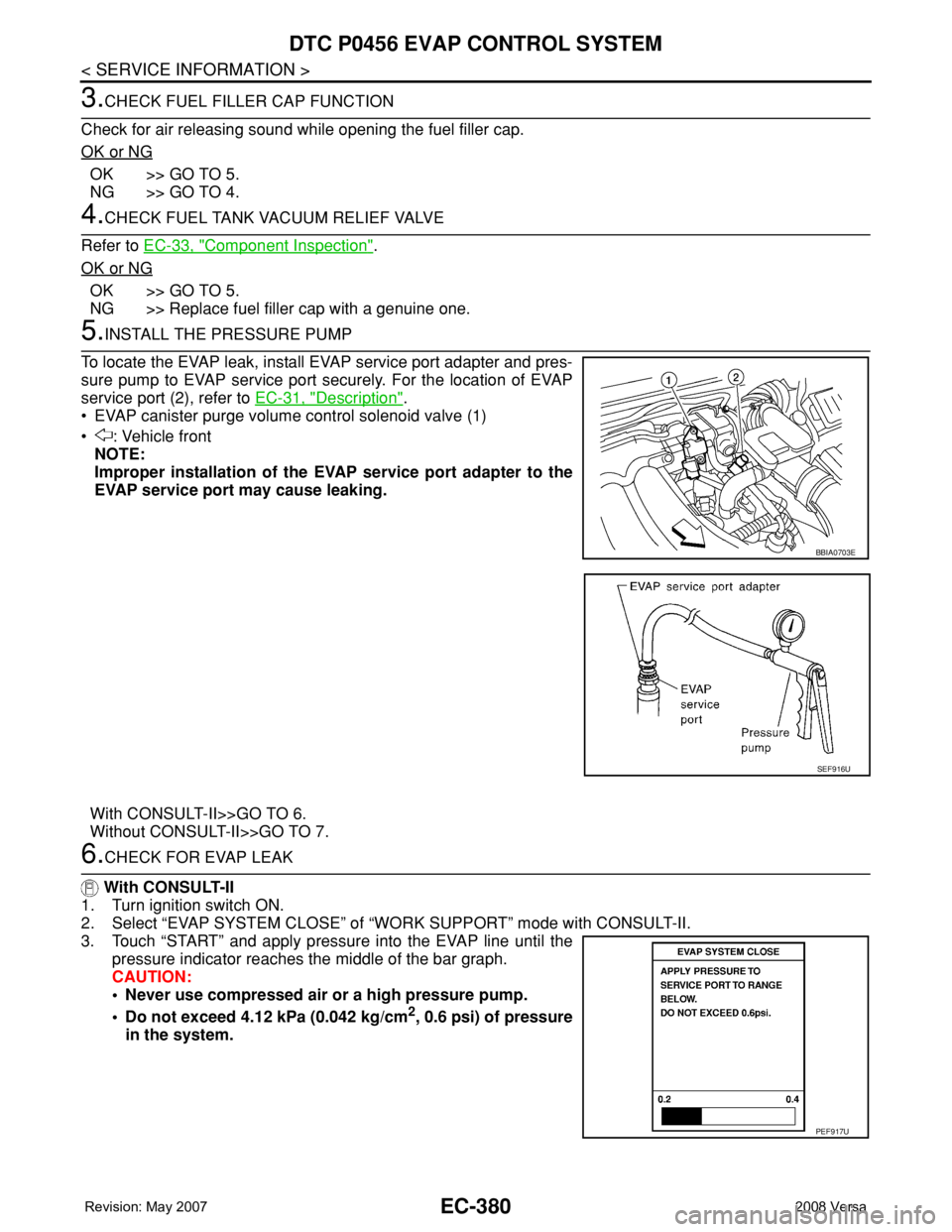
5.INSTALL THE PRESSURE PUMP
To locate the EVAP leak, install EVAP service port adapter and pres-
sure pump to EVAP service port securely. For the location of EVAP
service port (2), refer to EC-31, "
Description".
• EVAP canister purge volume control solenoid valve (1)
• : Vehicle front
NOTE:
Improper installation of the EVAP service port adapter to the
EVAP service port may cause leaking.
With CONSULT-II>>GO TO 6.
Without CONSULT-II>>GO TO 7.
6.CHECK FOR EVAP LEAK
With CONSULT-II
1. Turn ignition switch ON.
2. Select “EVAP SYSTEM CLOSE” of “WORK SUPPORT” mode with CONSULT-II.
3. Touch “START” and apply pressure into the EVAP line until the
pressure indicator reaches the middle of the bar graph.
CAUTION:
• Never use compressed air or a high pressure pump.
• Do not exceed 4.12 kPa (0.042 kg/cm
2, 0.6 psi) of pressure
in the system.
BBIA0703E
SEF916U
PEF917U
Page 1457 of 2771
DTC P0456 EVAP CONTROL SYSTEM
EC-383
< SERVICE INFORMATION >
C
D
E
F
G
H
I
J
K
L
MA
EC
N
P O
Check vacuum hoses for clogging or disconnection. Refer to EC-99, "Vacuum Hose Drawing".
OK or NG
OK >> GO TO 15.
NG >> Repair or reconnect the hose.
15.CHECK EVAP CANISTER PURGE VOLUME CONTROL SOLENOID VALVE
Refer to EC-337, "
Component Inspection".
OK or NG
OK >> GO TO 16.
NG >> Replace EVAP canister purge volume control solenoid valve.
16.CHECK FUEL TANK TEMPERATURE SENSOR
Refer to EC-273, "
Component Inspection".
OK or NG
OK >> GO TO 17.
NG >> Replace fuel level sensor unit.
17.CHECK EVAP CONTROL SYSTEM PRESSURE SENSOR
Refer to EC-361, "
Component Inspection".
OK or NG
OK >> GO TO 18.
NG >> Replace EVAP control system pressure sensor.
18.CHECK EVAP PURGE LINE
Check EVAP purge line (pipe, rubber tube, fuel tank and EVAP canister) for cracks or improper connection.
Refer to EC-31, "
Description".
OK or NG
OK >> GO TO 19.
NG >> Repair or reconnect the hose.
19.CLEAN EVAP PURGE LINE
Clean EVAP purge line (pipe and rubber tube) using air blower.
>> GO TO 20.
20.CHECK EVAP/ORVR LINE
Check EVAP/ORVR line between EVAP canister and fuel tank for clogging, kink, looseness and improper con-
nection. For location, refer to EC-38
.
OK or NG
OK >> GO TO 21.
NG >> Repair or replace hoses and tubes.
21.CHECK RECIRCULATION LINE
Check recirculation line between filler neck tube and fuel tank for clogging, kink, cracks, looseness and
improper connection.
OK or NG
OK >> GO TO 22.
NG >> Repair or replace hose, tube or filler neck tube.
22.CHECK REFUELING EVAP VAPOR CUT VALVE
Refer to EC-40, "
Component Inspection".
OK or NG
OK >> GO TO 23.
NG >> Replace refueling EVAP vapor cut valve with fuel tank.
23.CHECK FUEL LEVEL SENSOR
Refer to FL-5
.
Page 1459 of 2771
DTC P0460 FUEL LEVEL SENSOR
EC-385
< SERVICE INFORMATION >
C
D
E
F
G
H
I
J
K
L
MA
EC
N
P O
DTC P0460 FUEL LEVEL SENSOR
Component DescriptionINFOID:0000000001702885
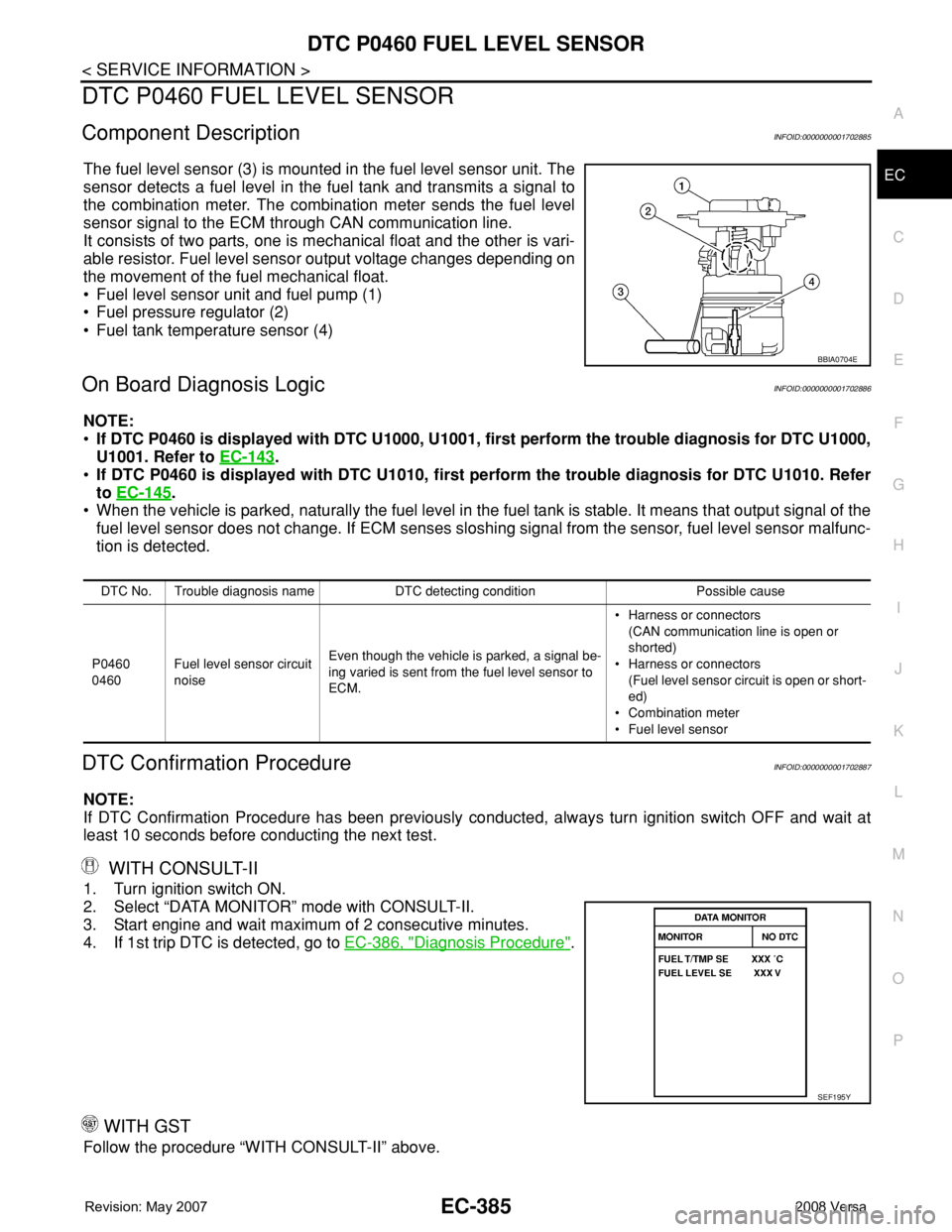
The fuel level sensor (3) is mounted in the fuel level sensor unit. The
sensor detects a fuel level in the fuel tank and transmits a signal to
the combination meter. The combination meter sends the fuel level
sensor signal to the ECM through CAN communication line.
It consists of two parts, one is mechanical float and the other is vari-
able resistor. Fuel level sensor output voltage changes depending on
the movement of the fuel mechanical float.
• Fuel level sensor unit and fuel pump (1)
• Fuel pressure regulator (2)
• Fuel tank temperature sensor (4)
On Board Diagnosis LogicINFOID:0000000001702886
NOTE:
•If DTC P0460 is displayed with DTC U1000, U1001, first perform the trouble diagnosis for DTC U1000,
U1001. Refer to EC-143
.
•If DTC P0460 is displayed with DTC U1010, first perform the trouble diagnosis for DTC U1010. Refer
to EC-145
.
• When the vehicle is parked, naturally the fuel level in the fuel tank is stable. It means that output signal of the
fuel level sensor does not change. If ECM senses sloshing signal from the sensor, fuel level sensor malfunc-
tion is detected.
DTC Confirmation ProcedureINFOID:0000000001702887
NOTE:
If DTC Confirmation Procedure has been previously conducted, always turn ignition switch OFF and wait at
least 10 seconds before conducting the next test.
WITH CONSULT-II
1. Turn ignition switch ON.
2. Select “DATA MONITOR” mode with CONSULT-II.
3. Start engine and wait maximum of 2 consecutive minutes.
4. If 1st trip DTC is detected, go to EC-386, "
Diagnosis Procedure".
WITH GST
Follow the procedure “WITH CONSULT-II” above.
BBIA0704E
DTC No. Trouble diagnosis name DTC detecting condition Possible cause
P0460
0460Fuel level sensor circuit
noiseEven though the vehicle is parked, a signal be-
ing varied is sent from the fuel level sensor to
ECM.• Harness or connectors
(CAN communication line is open or
shorted)
• Harness or connectors
(Fuel level sensor circuit is open or short-
ed)
• Combination meter
• Fuel level sensor
SEF195Y
Page 1461 of 2771
DTC P0461 FUEL LEVEL SENSOR
EC-387
< SERVICE INFORMATION >
C
D
E
F
G
H
I
J
K
L
MA
EC
N
P O
DTC P0461 FUEL LEVEL SENSOR
Component DescriptionINFOID:0000000001702890
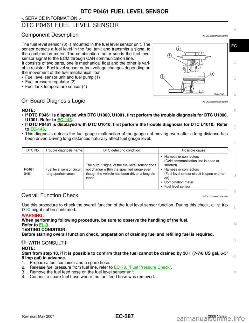
The fuel level sensor (3) is mounted in the fuel level sensor unit. The
sensor detects a fuel level in the fuel tank and transmits a signal to
the combination meter. The combination meter sends the fuel level
sensor signal to the ECM through CAN communication line.
It consists of two parts, one is mechanical float and the other is vari-
able resistor. Fuel level sensor output voltage changes depending on
the movement of the fuel mechanical float.
• Fuel level sensor unit and fuel pump (1)
• Fuel pressure regulator (2)
• Fuel tank temperature sensor (4)
On Board Diagnosis LogicINFOID:0000000001702891
NOTE:
•If DTC P0461 is displayed with DTC U1000, U1001, first perform the trouble diagnosis for DTC U1000,
U1001. Refer to EC-143
.
•If DTC P0461 is displayed with DTC U1010, first perform the trouble diagnosis for DTC U1010. Refer
to EC-145
.
• This diagnosis detects the fuel gauge malfunction of the gauge not moving even after a long distance has
been driven.Driving long distances naturally affect fuel gauge level.
Overall Function CheckINFOID:0000000001702892
Use this procedure to check the overall function of the fuel level sensor function. During this check, a 1st trip
DTC might not be confirmed.
WARNING:
When performing following procedure, be sure to observe the handling of the fuel.
Refer to FL-9
.
TESTING CONDITION:
Before starting overall function check, preparation of draining fuel and refilling fuel is required.
WITH CONSULT-II
NOTE:
Start from step 10, if it is possible to confirm that the fuel cannot be drained by 30 (7-7/8 US gal, 6-5/
8 Imp gal) in advance.
1. Prepare a fuel container and a spare hose.
2. Release fuel pressure from fuel line, refer to EC-78, "
Fuel Pressure Check".
3. Remove the fuel feed hose on the fuel level sensor unit.
4. Connect a spare fuel hose where the fuel feed hose was removed.
BBIA0704E
DTC No. Trouble diagnosis name DTC detecting condition Possible cause
P0461
0461Fuel level sensor circuit
range/performanceThe output signal of the fuel level sensor does
not change within the specified range even
though the vehicle has been driven a long dis-
tance.• Harness or connectors
(CAN communication line is open or
shorted)
• Harness or connectors
(Fuel level sensor circuit is open or short-
ed)
• Combination meter
• Fuel level sensor
Page 1462 of 2771
EC-388
< SERVICE INFORMATION >
DTC P0461 FUEL LEVEL SENSOR
5. Turn ignition switch OFF and wait at least 10 seconds then turn
ON.
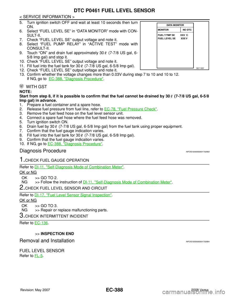
6. Select “FUEL LEVEL SE” in “DATA MONITOR” mode with CON-
SULT-II.
7. Check “FUEL LEVEL SE” output voltage and note it.
8. Select “FUEL PUMP RELAY” in “ACTIVE TEST” mode with
CONSULT-II.
9. Touch “ON” and drain fuel approximately 30 (7-7/8 US gal, 6-
5/8 Imp gal) and stop it.
10. Check “FUEL LEVEL SE” output voltage and note it.
11. Fill fuel into the fuel tank for 30 (7-7/8 US gal, 6-5/8 Imp gal).
12. Check “FUEL LEVEL SE” output voltage and note it.
13. Confirm whether the voltage changes more than 0.03V during step 7 to 10 and 10 to 12.
If NG, go to EC-388, "
Diagnosis Procedure".
WITH GST
NOTE:
Start from step 8, if it is possible to confirm that the fuel cannot be drained by 30 (7-7/8 US gal, 6-5/8
Imp gal) in advance.
1. Prepare a fuel container and a spare hose.
2. Release fuel pressure from fuel line, refer to EC-78, "
Fuel Pressure Check".
3. Remove the fuel feed hose on the fuel level sensor unit.
4. Connect a spare fuel hose where the fuel feed hose was removed.
5. Turn ignition switch ON.
6. Drain fuel by 30 (7-7/8 US gal, 6-5/8 Imp gal) from the fuel tank using proper equipment.
7. Confirm that the fuel gauge indication varies.
8. Fill fuel into the fuel tank for 30 (7-7/8 US gal, 6-5/8 Imp gal).
9. Confirm that the fuel gauge indication varies.
10. If NG, go to EC-388, "
Diagnosis Procedure".
Diagnosis ProcedureINFOID:0000000001702893
1.CHECK FUEL GAUGE OPERATION
Refer to DI-11, "
Self-Diagnosis Mode of Combination Meter".
OK or NG
OK >> GO TO 2.
NG >> Follow the instruction of DI-11, "
Self-Diagnosis Mode of Combination Meter".
2.CHECK FUEL LEVEL SENSOR AND CIRCUIT
Refer to DI-17, "
Fuel Level Sensor Signal Inspection".
OK or NG
OK >> GO TO 3.
NG >> Repair or replace malfunctioning parts.
3.CHECK INTERMITTENT INCIDENT
Refer to EC-136
.
>>INSPECTION END
Removal and InstallationINFOID:0000000001702894
FUEL LEVEL SENSOR
Refer to FL-5.
SEF195Y
Page 1463 of 2771
DTC P0462, P0463 FUEL LEVEL SENSOR
EC-389
< SERVICE INFORMATION >
C
D
E
F
G
H
I
J
K
L
MA
EC
N
P O
DTC P0462, P0463 FUEL LEVEL SENSOR
Component DescriptionINFOID:0000000001702895
The fuel level sensor (3) is mounted in the fuel level sensor unit. The
sensor detects a fuel level in the fuel tank and transmits a signal to
the combination meter. The combination meter. sends the fuel level
sensor signal to the ECM through CAN communication line.
It consists of two parts, one is mechanical float and the other is vari-
able resistor. Fuel level sensor output voltage changes depending on
the movement of the fuel mechanical float.
• Fuel level sensor unit and fuel pump (1)
• Fuel pressure regulator (2)
• Fuel tank temperature sensor (4)
On Board Diagnosis LogicINFOID:0000000001702896
NOTE:
•If DTC P0462 or P0463 is displayed with DTC U1000, U1001, first perform the trouble diagnosis for
DTC U1000, U1001. Refer to EC-143
.
•If DTC P0462 or P0463 is displayed with DTC U1010, first perform the trouble diagnosis for DTC
U1010. Refer to EC-145
.
• ECM receives two signals from the fuel level sensor circuit.One is fuel level sensor power supply circuit, and
the other is fuel level sensor ground circuit.This diagnosis indicates the former, to detect open or short circuit
malfunction.
DTC Confirmation ProcedureINFOID:0000000001702897
NOTE:
If DTC Confirmation Procedure has been previously conducted, always turn ignition switch OFF and wait at
least 10 seconds before conducting the next test.
TESTING CONDITION:
Before performing the following procedure, confirm that battery voltage is more than 11V at ignition
switch ON.
WITH CONSULT-II
1. Turn ignition switch ON.
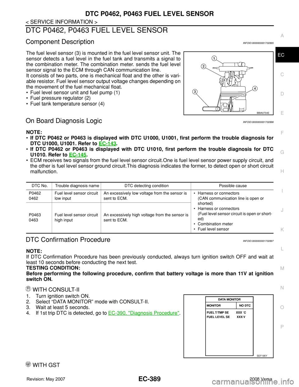
2. Select “DATA MONITOR” mode with CONSULT-II.
3. Wait at least 5 seconds.
4. If 1st trip DTC is detected, go to EC-390, "
Diagnosis Procedure".
WITH GST
BBIA0704E
DTC No. Trouble diagnosis name DTC detecting condition Possible cause
P0462
0462Fuel level sensor circuit
low inputAn excessively low voltage from the sensor is
sent to ECM.• Harness or connectors
(CAN communication line is open or
shorted)
• Harness or connectors
(Fuel level sensor circuit is open or short-
ed)
• Combination meter
• Fuel level sensor P0463
0463Fuel level sensor circuit
high inputAn excessively high voltage from the sensor is
sent to ECM.
SEF195Y
Page 1600 of 2771
EC-526
< SERVICE INFORMATION >
FUEL PUMP
FUEL PUMP
DescriptionINFOID:0000000001703065
SYSTEM DESCRIPTION
*: ECM determines the start signal status by the signals of engine speed and battery voltage.
The ECM activates the fuel pump for several seconds after the ignition switch is turned ON to improve engine
startability. If the ECM receives a engine speed signal from the crankshaft position sensor (POS) and cam-
shaft position sensor (PHASE), it knows that the engine is rotating, and causes the pump to operate. If the
engine speed signal is not received when the ignition switch is ON, the engine stalls. The ECM stops pump
operation and prevents battery discharging, thereby improving safety. The ECM does not directly drive the fuel
pump. It controls the ON/OFF fuel pump relay, which in turn controls the fuel pump.
COMPONENT DESCRIPTION
A turbine type design fuel pump is used in the fuel tank.
• Fuel level sensor unit and fuel pump (1)
• Fuel pressure regulator (2)
• Fuel level sensor (3)
• Fuel tank temperature sensor (4)
CONSULT-II Reference Value in Data Monitor ModeINFOID:0000000001703066
Specification data are reference values.
Sensor Input Signal to ECM ECM Function Actuator
Crankshaft position sensor (POS)
Camshaft position sensor (PHASE)Engine speed*
Fuel pump control Fuel pump relay
Battery Battery voltage*
Condition Fuel pump operation
Ignition switch is turned to ON Operates for 1 second
Engine running and crankingOperates
Engine: StoppedStops in 1.5 seconds
Except as shown aboveSt ops
BBIA0704E
MONITOR ITEM CONDITION SPECIFICATION
FUEL PUMP RLY• For 1 second after turning ignition switch ON
• Engine running or crankingON
• Except above conditions OFF
Page 1821 of 2771

FL-1
ENGINE
C
D
E
F
G
H
I
J
K
L
M
SECTION FL
A
FL
N
O
P
CONTENTS
FUEL SYSTEM
SERVICE INFORMATION ............................2
PRECAUTIONS ...................................................2
Precaution for Supplemental Restraint System
(SRS) "AIR BAG" and "SEAT BELT PRE-TEN-
SIONER" ...................................................................
2
PREPARATION ...................................................3
Special Service Tool .................................................3
Commercial Service Tool ..........................................3
FUEL SYSTEM ....................................................4
Checking Fuel Line ...................................................4
General Precaution ...................................................4
FUEL LEVEL SENSOR UNIT, FUEL FILTER
AND FUEL PUMP ASSEMBLY .........................
5
Component ...............................................................5
Removal and Installation ..........................................5
FUEL TANK .......................................................9
Component ...............................................................9
Removal and Installation ..........................................9
SERVICE DATA AND SPECIFICATIONS
(SDS) .................................................................
14
Standard and Limit ..................................................14
Page 1823 of 2771
PREPARATION
FL-3
< SERVICE INFORMATION >
C
D
E
F
G
H
I
J
K
L
MA
FL
N
P O
PREPARATION
Special Service ToolINFOID:0000000001703095
The actual shapes of the Kent-Moore tools may differ from those of the special tools illustrated here.
Commercial Service ToolINFOID:0000000001703096
Tool number
(Kent-Moore No.)
Tool nameDescription
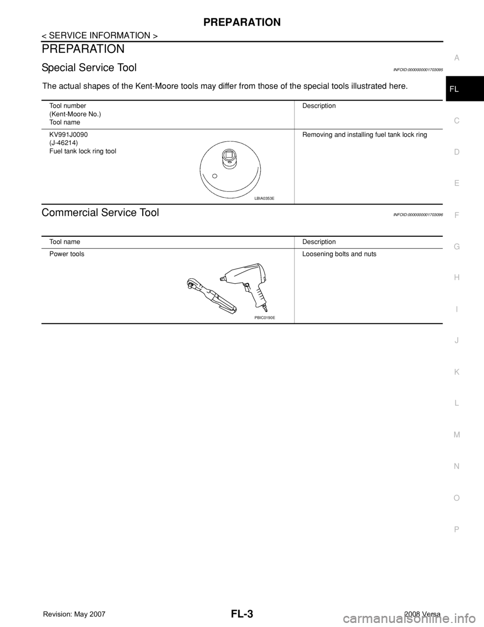
KV991J0090
(J-46214)
Fuel tank lock ring toolRemoving and installing fuel tank lock ring
LBIA0353E
Tool nameDescription
Power toolsLoosening bolts and nuts
PBIC0190E
Page 1824 of 2771
FL-4
< SERVICE INFORMATION >
FUEL SYSTEM
FUEL SYSTEM
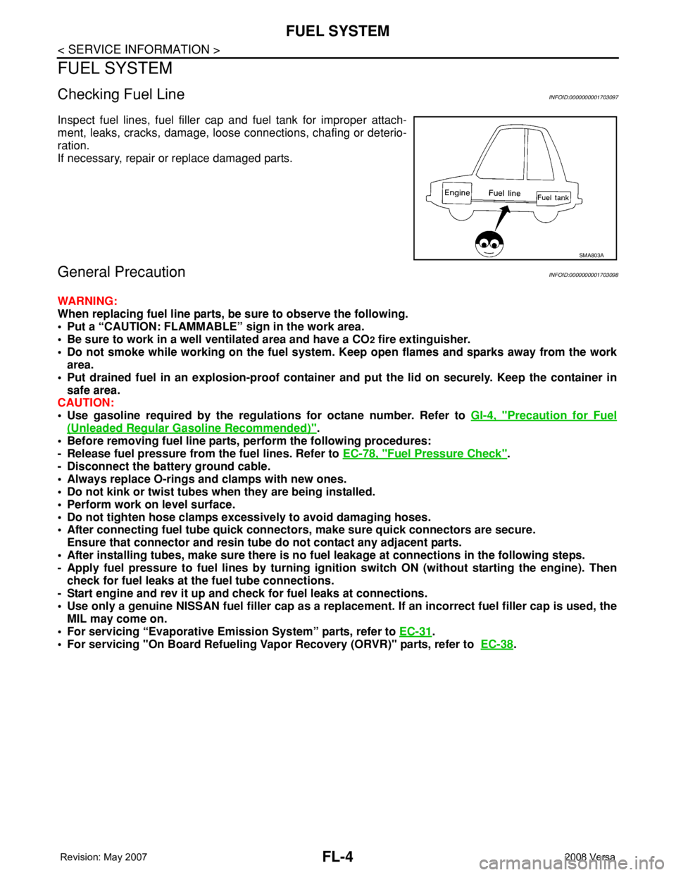
Checking Fuel LineINFOID:0000000001703097
Inspect fuel lines, fuel filler cap and fuel tank for improper attach-
ment, leaks, cracks, damage, loose connections, chafing or deterio-
ration.
If necessary, repair or replace damaged parts.
General PrecautionINFOID:0000000001703098
WARNING:
When replacing fuel line parts, be sure to observe the following.
• Put a “CAUTION: FLAMMABLE” sign in the work area.
• Be sure to work in a well ventilated area and have a CO
2 fire extinguisher.
• Do not smoke while working on the fuel system. Keep open flames and sparks away from the work
area.
• Put drained fuel in an explosion-proof container and put the lid on securely. Keep the container in
safe area.
CAUTION:
• Use gasoline required by the regulations for octane number. Refer to GI-4, "
Precaution for Fuel
(Unleaded Regular Gasoline Recommended)".
• Before removing fuel line parts, perform the following procedures:
- Release fuel pressure from the fuel lines. Refer to EC-78, "
Fuel Pressure Check".
- Disconnect the battery ground cable.
• Always replace O-rings and clamps with new ones.
• Do not kink or twist tubes when they are being installed.
• Perform work on level surface.
• Do not tighten hose clamps excessively to avoid damaging hoses.
• After connecting fuel tube quick connectors, make sure quick connectors are secure.
Ensure that connector and resin tube do not contact any adjacent parts.
• After installing tubes, make sure there is no fuel leakage at connections in the following steps.
- Apply fuel pressure to fuel lines by turning ignition switch ON (without starting the engine). Then
check for fuel leaks at the fuel tube connections.
- Start engine and rev it up and check for fuel leaks at connections.
• Use only a genuine NISSAN fuel filler cap as a replacement. If an incorrect fuel filler cap is used, the
MIL may come on.
• For servicing “Evaporative Emission System” parts, refer to EC-31
.
• For servicing "On Board Refueling Vapor Recovery (ORVR)" parts, refer to EC-38
.
SMA803A