Cooling NISSAN TIIDA 2008 Service Manual PDF
[x] Cancel search | Manufacturer: NISSAN, Model Year: 2008, Model line: TIIDA, Model: NISSAN TIIDA 2008Pages: 2771, PDF Size: 60.61 MB
Page 2425 of 2771
REFRIGERANT LINES
MTC-87
< SERVICE INFORMATION >
C
D
E
F
G
H
I
K
L
MA
B
MTC
N
O
P
Check all around the service valves. Ensure service valve caps are secured on the service valves (to
prevent leaks).
NOTE:
After removing A/C manifold gauge set from service valves, wipe any residue from valves to prevent any
false readings by leak detector.
• Cooling unit (Evaporator)
With engine OFF, turn blower fan on “High” for at least 15 seconds to dissipate any refrigerant trace in
the cooling unit. Wait a minimum of 10 minutes accumulation time (refer to the manufacturer’s recom-
mended procedure for actual wait time) before inserting the leak detector probe into the drain hose.
Keep the probe inserted for at least 10 seconds. Use caution not to contaminate the probe tip with water
or dirt that may be in the drain hose.
5. If a leak detector detects a leak, verify at least once by blowing compressed air into area of suspected
leak, then repeat check as outlined above.
6. Do not stop when one leak is found. Continue to check for additional leaks at all system components.
If no leaks are found, perform steps 7-10.
7. Start engine.
8. Set the heater A/C control as follows;
a. A/C switch: ON
b. Mode control dial position: VENT (Ventilation)
c. Intake door lever position: Recirculation
d. Max. cold temperature
e. Fan speed: High
9. Run engine at 1,500 rpm for at least 2 minutes.
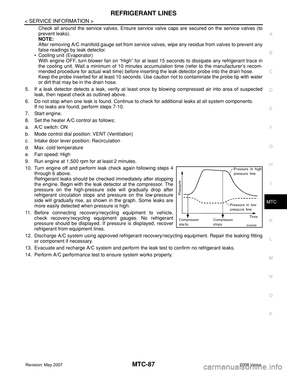
10. Turn engine off and perform leak check again following steps 4
through 6 above.
Refrigerant leaks should be checked immediately after stopping
the engine. Begin with the leak detector at the compressor. The
pressure on the high-pressure side will gradually drop after
refrigerant circulation stops and pressure on the low-pressure
side will gradually rise, as shown in the graph. Some leaks are
more easily detected when pressure is high.
11. Before connecting recovery/recycling equipment to vehicle,
check recovery/recycling equipment gauges. No refrigerant
pressure should be displayed. If pressure is displayed, recover
refrigerant from equipment lines.
12. Discharge A/C system using approved refrigerant recovery/recycling equipment. Repair the leaking fitting
or component if necessary.
13. Evacuate and recharge A/C system and perform the leak test to confirm no refrigerant leaks.
14. Perform A/C performance test to ensure system works properly.
SHA839E
Page 2449 of 2771

PG-16
< SERVICE INFORMATION >
IPDM E/R (INTELLIGENT POWER DISTRIBUTION MODULE ENGINE ROOM)
IPDM E/R (INTELLIGENT POWER DISTRIBUTION MODULE ENGINE
ROOM)
System DescriptionINFOID:0000000001704697
• IPDM E/R (Intelligent Power Distribution Module Engine Room) integrates the relay box and fuse block
which were originally placed in engine compartment. It controls integrated relays via IPDM E/R control cir-
cuits.
• IPDM E/R-integrated control circuits perform ON-OFF operation of relays, CAN communication control, oil
pressure switch signal reception, etc.
• It controls operation of each electrical component via ECM, BCM and CAN communication lines.
CAUTION:
None of the IPDM E/R integrated relays can be removed.
SYSTEMS CONTROLLED BY IPDM E/R
1. Lamp control
Using CAN communication lines, it receives signals from the BCM and controls the following lamps:
• Headlamps (High, Low)
• Parking lamps
• Tail and license plate lamps
• Front fog lamps
2. Wiper control
Using CAN communication lines, it receives signals from the BCM and controls the front wipers.
3. Rear window defogger relay control
Using CAN communication lines, it receives signals from the BCM and controls the rear window defogger
relay.
4. A/C compressor control
Using CAN communication lines, it receives signals from the ECM and controls the A/C compressor
(magnet clutch).
5. Starter control
Using CAN communication lines, it receives signals from the BCM and controls the starter relay.
6. Cooling fan control
Using CAN communication lines, it receives signals from the ECM and controls the cooling fan relays.
7. Horn control
Using CAN communication lines, it receives signals from the BCM and controls the horn relay.
8. Daytime light system control (Canada only)
Using CAN communication lines, it receives signals from the BCM and controls the daytime light relay.
CAN COMMUNICATION LINE CONTROL
With CAN communication, by connecting each control unit using two communication lines (CAN L-line, CAN
H-line), it is possible to transmit a maximum amount of information with minimum wiring. Each control unit can
transmit and receive data, and reads necessary information only.
1. Fail-safe control
• When CAN communication with other control units is impossible, IPDM E/R performs fail-safe control.
After CAN communication returns to normal operation, it also returns to normal control.
• Operation of control parts by IPDM E/R during fail-safe mode is as follows:
Controlled system Fail-safe mode
Headlamp• With the ignition switch ON, headlamp low relay is ON, headlamp high relays are OFF, and
daytime light system (Canada only) is OFF.
• With the ignition switch OFF, the headlamp relays are OFF.
Tail, license plate and parking lamps • With the ignition switch ON, the tail lamp relay is ON.
• With the ignition switch OFF, the tail lamp relay is OFF.
Cooling fan• With the ignition switch ON, cooling fan relay-1, relay-2, and relay-3 are ON.
• With the ignition switch OFF, all cooling fan relays are OFF.
Front wiperUntil the ignition switch is turned off, the front wiper relays remain in the same status they
were in just before fail−safe control was initiated.
Page 2452 of 2771
IPDM E/R (INTELLIGENT POWER DISTRIBUTION MODULE ENGINE ROOM)
PG-19
< SERVICE INFORMATION >
C
D
E
F
G
H
I
J
L
MA
B
PG
N
O
P
*1 Perform monitoring of IPDM E/R data with the ignition switch ON. When the ignition switch is in ACC position, display may not be cor-
rect.
*2 This item is displayed, but does not function.
CAN DIAG SUPPORT MNTR
Refer to LAN-8 .
ACTIVE TEST
Display Item List
Auto Active TestINFOID:0000000001704701
DESCRIPTION
• In auto active test mode, operation inspection can be performed when IPDM E/R sends a drive signal to the
following systems:
- Rear window defogger
- Front wipers
- Tail, license and parking lamps
- Daytime lamp system (Canada only)
- Front fog lamps
- Headlamps (High, Low)
- A/C compressor (magnet clutch)
- Cooling fan
OPERATION PROCEDURE
1. Close hood and front door RH, and lift wiper arms away from windshield (to prevent glass damage by
wiper operation).
NOTE:
When auto active test is performed with hood opened, sprinkle water on windshield beforehand.
2. Turn ignition switch OFF.
3. Turn ignition switch ON and, within 20 seconds, press front door switch LH 20 times. Then turn ignition
switch OFF.
4. Turn ignition switch ON within 10 seconds after ignition switch OFF.
5. When auto active test mode is actuated, horn chirps once.
6. After a series of operations is repeated three times, auto active test is completed.
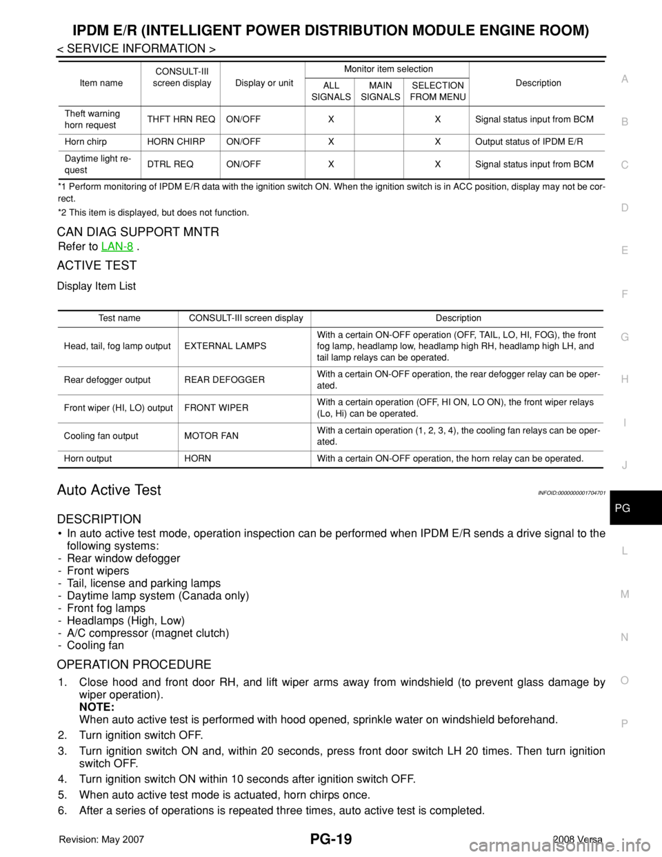
Theft warning
horn requestTHFT HRN REQ ON/OFF X X Signal status input from BCM
Horn chirp HORN CHIRP ON/OFF X X Output status of IPDM E/R
Daytime light re-
questDTRL REQ ON/OFF X X Signal status input from BCM Item nameCONSULT-III
screen display Display or unitMonitor item selection
Description
ALL
SIGNALSMAIN
SIGNALSSELECTION
FROM MENU
Test name CONSULT-III screen display Description
Head, tail, fog lamp output EXTERNAL LAMPSWith a certain ON-OFF operation (OFF, TAIL, LO, HI, FOG), the front
fog lamp, headlamp low, headlamp high RH, headlamp high LH, and
tail lamp relays can be operated.
Rear defogger output REAR DEFOGGERWith a certain ON-OFF operation, the rear defogger relay can be oper-
ated.
Front wiper (HI, LO) output FRONT WIPERWith a certain operation (OFF, HI ON, LO ON), the front wiper relays
(Lo, Hi) can be operated.
Cooling fan output MOTOR FANWith a certain operation (1, 2, 3, 4), the cooling fan relays can be oper-
ated.
Horn output HORN With a certain ON-OFF operation, the horn relay can be operated.
Page 2453 of 2771
PG-20
< SERVICE INFORMATION >
IPDM E/R (INTELLIGENT POWER DISTRIBUTION MODULE ENGINE ROOM)
NOTE:
When auto active test mode has to be cancelled halfway, turn ignition switch OFF.
CAUTION:
Be sure to perform BL-37, "
Door Switch Check (Hatchback)" when the auto active test cannot be
performed.
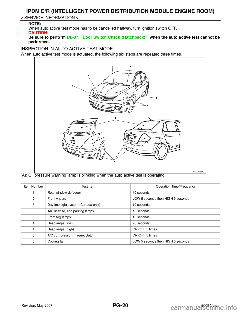
INSPECTION IN AUTO ACTIVE TEST MODE
When auto active test mode is actuated, the following six steps are repeated three times.
(A): Oil pressure warning lamp is blinking when the auto active test is operating.
WKIA5988E
Item Number Test Item Operation Time/Frequency
1 Rear window defogger 10 seconds
2 Front wipers LOW 5 seconds then HIGH 5 seconds
3 Daytime light system (Canada only) 10 seconds
3 Tail, license, and parking lamps 10 seconds
3 Front fog lamps 10 seconds
4 Headlamps (low) 20 seconds
4 Headlamps (high) ON-OFF 5 times
5 A/C compressor (magnet clutch) ON-OFF 5 times
6 Cooling fan LOW 5 seconds then HIGH 5 seconds
Page 2454 of 2771
IPDM E/R (INTELLIGENT POWER DISTRIBUTION MODULE ENGINE ROOM)
PG-21
< SERVICE INFORMATION >
C
D
E
F
G
H
I
J
L
MA
B
PG
N
O
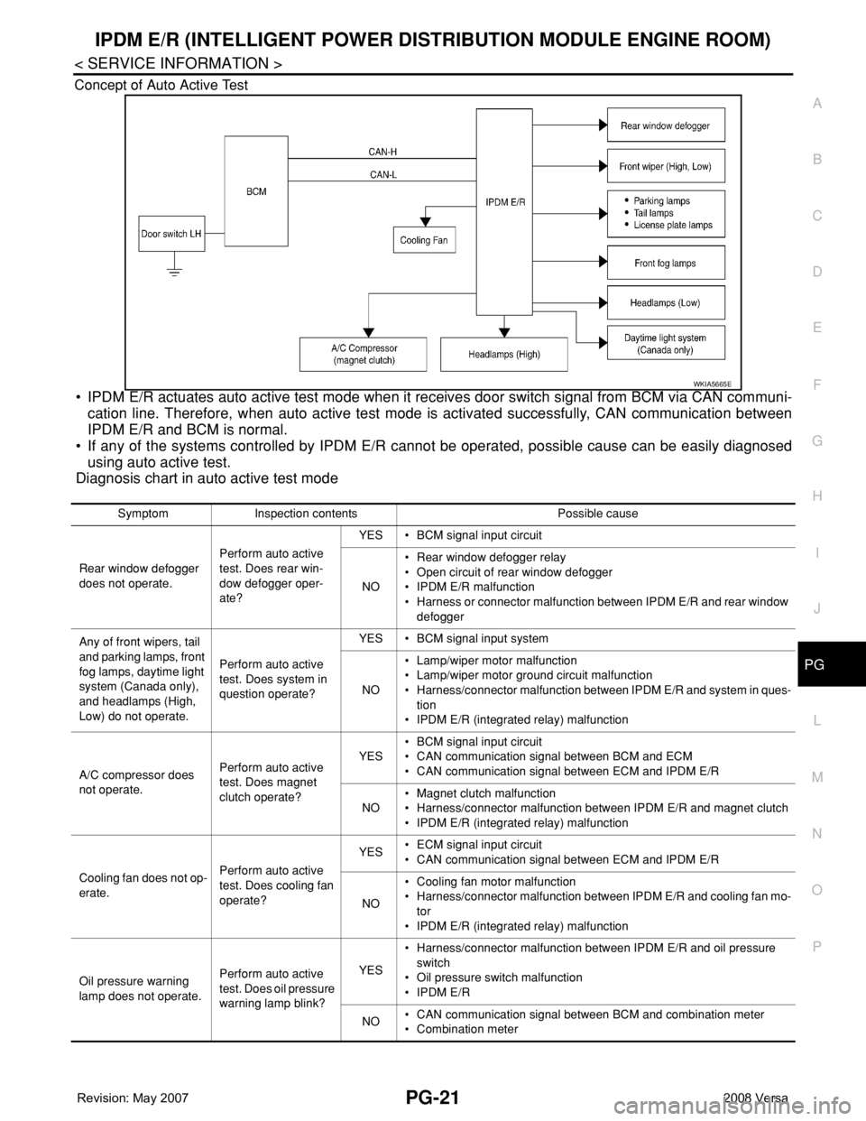
P Concept of Auto Active Test
• IPDM E/R actuates auto active test mode when it receives door switch signal from BCM via CAN communi-
cation line. Therefore, when auto active test mode is activated successfully, CAN communication between
IPDM E/R and BCM is normal.
• If any of the systems controlled by IPDM E/R cannot be operated, possible cause can be easily diagnosed
using auto active test.
Diagnosis chart in auto active test mode
WKIA5665E
Symptom Inspection contents Possible cause
Rear window defogger
does not operate.Perform auto active
test. Does rear win-
dow defogger oper-
ate?YES • BCM signal input circuit
NO• Rear window defogger relay
• Open circuit of rear window defogger
• IPDM E/R malfunction
• Harness or connector malfunction between IPDM E/R and rear window
defogger
Any of front wipers, tail
and parking lamps, front
fog lamps, daytime light
system (Canada only),
and headlamps (High,
Low) do not operate.Perform auto active
test. Does system in
question operate?YES • BCM signal input system
NO• Lamp/wiper motor malfunction
• Lamp/wiper motor ground circuit malfunction
• Harness/connector malfunction between IPDM E/R and system in ques-
tion
• IPDM E/R (integrated relay) malfunction
A/C compressor does
not operate.Perform auto active
test. Does magnet
clutch operate?YES• BCM signal input circuit
• CAN communication signal between BCM and ECM
• CAN communication signal between ECM and IPDM E/R
NO• Magnet clutch malfunction
• Harness/connector malfunction between IPDM E/R and magnet clutch
• IPDM E/R (integrated relay) malfunction
Cooling fan does not op-
erate.Perform auto active
test. Does cooling fan
operate?YES• ECM signal input circuit
• CAN communication signal between ECM and IPDM E/R
NO• Cooling fan motor malfunction
• Harness/connector malfunction between IPDM E/R and cooling fan mo-
tor
• IPDM E/R (integrated relay) malfunction
Oil pressure warning
lamp does not operate.Perform auto active
test. Does oil pressure
warning lamp blink?YES• Harness/connector malfunction between IPDM E/R and oil pressure
switch
• Oil pressure switch malfunction
• IPDM E/R
NO• CAN communication signal between BCM and combination meter
• Combination meter
Page 2456 of 2771

IPDM E/R (INTELLIGENT POWER DISTRIBUTION MODULE ENGINE ROOM)
PG-23
< SERVICE INFORMATION >
C
D
E
F
G
H
I
J
L
MA
B
PG
N
O
P
Terminal and Reference Value for IPDM E/RINFOID:0000000001704703
Te r m i n a lWire
colorSignal nameSignal
input/
outputMeasuring condition
Reference value
(Approx.) Ignition
switchOperation or condition
1 R Battery power supply Input OFF — Battery voltage
2 G Battery power supply Input OFF — Battery voltage
3YECM Relay Output—Ignition switch ON or START Battery voltage
Ignition switch OFF or ACC 0V
4GECM relay Output—Ignition switch ON or START Battery voltage
Ignition switch OFF or ACC 0V
6RDaytime light relay
controlInput ON Daytime light system active. Less than battery voltage
Daytime light system inactive. Battery voltage
7 G ECM relay control Input —Ignition switch ON or START 0V
Ignition switch OFF or ACC Battery voltage
8GThrottle control motor
relayOutput —Ignition switch ON or START Battery voltage
Ignition switch OFF or ACC 0V
11 W A/C compressor OutputON or
STARTA/C switch ON or defrost A/C
switchBattery voltage
A/C switch OFF or defrost A/C
switch0V
12 OIgnition switch sup-
plied powerInput —OFF or ACC 0V
ON or START Battery voltage
14LG
(M/T)
R
(A/T
or
CVT)Fuse 49 Output —Ignition switch ON or START Battery voltage
Ignition switch OFF or ACC 0V
15 V Fuse 50 Output —Ignition switch ON or START Battery voltage
Ignition switch OFF or ACC 0V
16 BR Fuse 51 Output —Ignition switch ON or START Battery voltage
Ignition switch OFF or ACC 0V
17 Y Battery power supply Output — — Battery voltage
19 R Starter motor Output START — Battery voltage
20L
(with
A/C)
LG
(with-
out A/
C)Cooling fan relay-1 Output —Conditions correct for cooling
fan low operation.Battery voltage
Conditions not correct for
cooling fan low operation.0V
22 G Battery power supply Input — — Battery voltage
23 L Cooling fan relay-2 Input —Conditions correct for cooling
fan high operationBattery voltage
Conditions not correct for
cooling fan high operation0V
Page 2457 of 2771

PG-24
< SERVICE INFORMATION >
IPDM E/R (INTELLIGENT POWER DISTRIBUTION MODULE ENGINE ROOM)
24 Y Cooling fan relay-3 Output —Conditions correct for cooling
fan high operationBattery voltage
Conditions not correct for
cooling fan high operation0V
26 OTail lamp relay (park-
ing lamps)Output — Lighting switch in 2nd position Battery voltage
27 BRTail lamp relay (park-
ing lamps)Output — Lighting switch in 2nd position Battery voltage
28 GRTail lamp relay (park-
ing lamps)Output — Lighting switch in 2nd position Battery voltage
29 PTail lamp relay (park-
ing lamps)Output — Lighting switch in 2nd position Battery voltage
30
(A/T
only)R Fuse 54 Output —Ignition switch ON or START Battery voltage
Ignition switch OFF or ACC 0V
31 O Fuse 55 Output —Ignition switch ON or START Battery voltage
Ignition switch OFF or ACC 0V
32 LWiper high speed sig-
nalOutputON or
STARTWiper switchOFF, LO, INT 0V
HI Battery voltage
33 YWiper low speed sig-
nalOutputON or
STARTWiper switchOFF 0V
LO or INT Battery voltage
35 BRStarter relay (inhibit
switch)InputON or
STARTSelector lever in "P" or "N"
(CVT or A/T) or clutch pedal
depressed (M/T)Battery voltage
Selector lever any other posi-
tion (CVT or A/T) or clutch
pedal released (M/T)0V
36 BR Fuel pump relay Output —Ignition switch ON or START Battery voltage
Ignition switch OFF or ACC 0V
37 G Oil pressure switch InputON or
STARTEngine running and oil pres-
sure within specificationBattery voltage
Engine not running or oil pres-
sure below specification0V
38 R Wiper auto stop signal InputON or
STARTWipers not in park position Battery voltage
Wipers in park position 0V
39 B Ground Input — — 0V
40 P CAN-L — ON — —
41 L CAN-H — ON — —
45 R Horn relay control Input —Horn switch PUSHED, alarm
switch activated or door lock/
unlock is confirmed when op-
erating lock system via the
keyfob0V
Horn switch released, alarm
not active, keyfob not activeBattery voltage
46 YThrottle control motor
relay controlInput —Ignition switch ON or START 0V
Ignition switch OFF or ACC Battery voltage
47 GRFuel pump relay con-
trolInput —
Ignition switch ON or START 0V
Ignition switch OFF or ACC Battery voltage Te r m i n a lWire
colorSignal nameSignal
input/
outputMeasuring condition
Reference value
(Approx.) Ignition
switchOperation or condition
Page 2473 of 2771
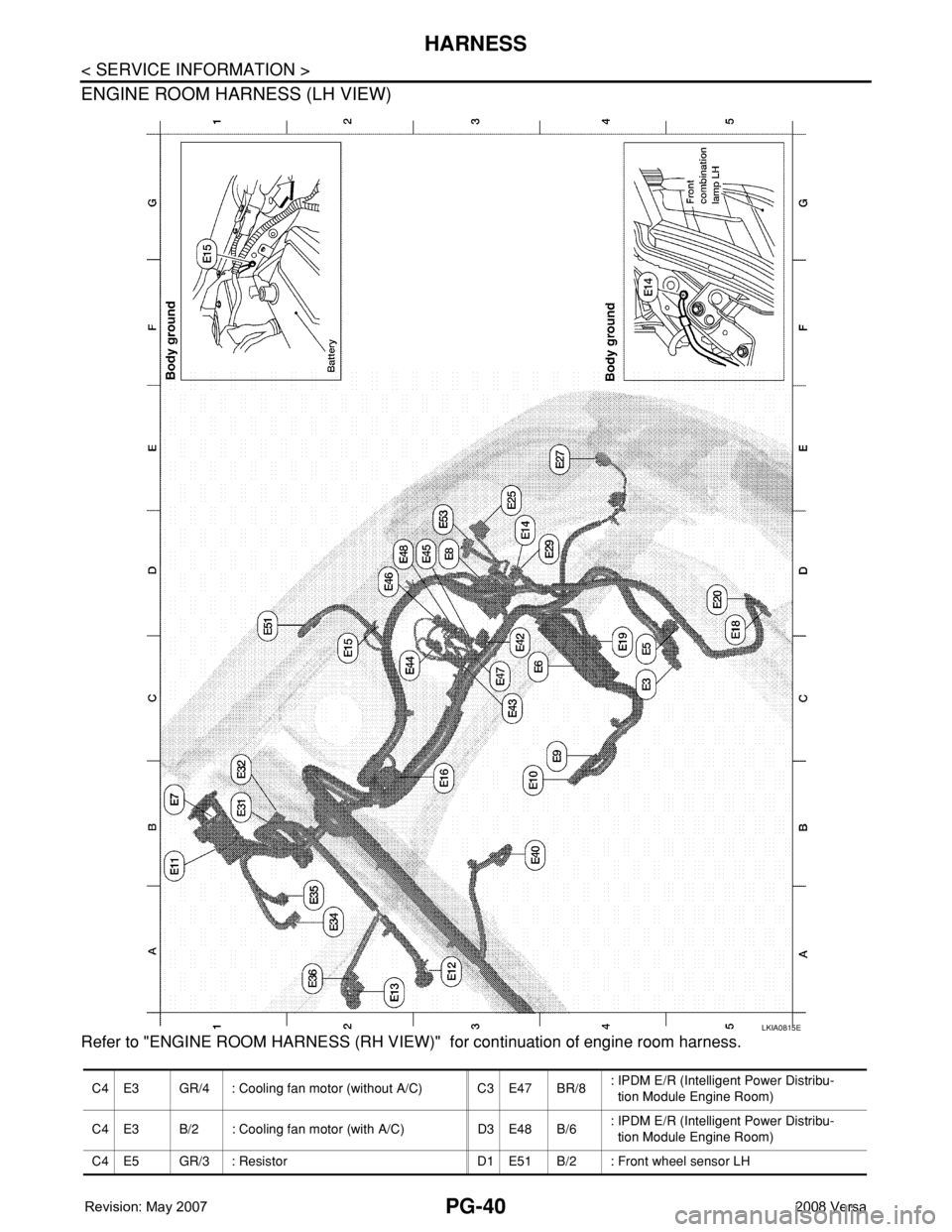
PG-40
< SERVICE INFORMATION >
HARNESS
ENGINE ROOM HARNESS (LH VIEW)
Refer to "ENGINE ROOM HARNESS (RH VIEW)" for continuation of engine room harness.
LKIA0815E
C4 E3 GR/4 : Cooling fan motor (without A/C) C3 E47 BR/8: IPDM E/R (Intelligent Power Distribu-
tion Module Engine Room)
C4 E3 B/2 : Cooling fan motor (with A/C) D3 E48 B/6: IPDM E/R (Intelligent Power Distribu-
tion Module Engine Room)
C4 E5 GR/3 : Resistor D1 E51 B/2 : Front wheel sensor LH
Page 2491 of 2771

PG-58
< SERVICE INFORMATION >
HARNESS
Wiring Diagram Codes (Cell Codes)
INFOID:0000000001704709
Use the chart below to find out what each wiring diagram code stands for.
Refer to the wiring diagram code in the alphabetical index to find the location (page number) of each wiring
diagram.
D3 D404 W/3 : Rear wiper motor
D4 D405 W/4 : Back door lock assembly
D4 D406 W/2 : Back door request switch
E2 D407 W/2 : High mounted stop lamp
D4 D408 BR/2 : Back door opener switch
E4 D409 B/1 : Condenser-1
C2 D410 — : Body ground
E3 D411 B/1 : Condenser-1
E1 D412 B/1 : Rear window defogger (+)
C2 D413 B/1 : Rear window defogger (-)
F3 D414 — : Body ground
Code Section Wiring Diagram Name
ABS BRC Anti-lock Brake System
A/C,M MTC Manual Air Conditioner
APPS1 EC Accelerator Pedal Position Sensor
A/F EC Air Fuel Ratio Sensor 1
A/FH EC Air Fuel Ratio Sensor 1 Heater
APPS2 EC Accelerator Pedal Position Sensor
APPS3 EC Accelerator Pedal Position Sensor
ASC/BS EC ASCD Brake Switch
ASC/SW EC ASCD Steering Switch
ASCBOF EC ASCD Brake Switch
ASCIND EC ASCD Indicator
AT/IND DI A/T Indicator Lamp
AUDIO AV Audio
BACK/L LT Back-up Lamp
BA/FTS AT A/T Fluid Temperature Sensor and TCM Power Supply
B/DOOR BL Back Door Opener
BRK/SW EC Brake Switch
CAN AT CAN Communication Line
CAN CVT CAN Communication Line
CAN EC CAN Communication Line
CAN LAN CAN System
CHARGE SC Charging System
CHIME DI Warning Chime
COOL/F EC Cooling Fan Control
COMBSW LT Combination Switch
CVTIND DI CVT Indicator Lamp
D/LOCK BL Power Door Lock
DEF GW Rear Window Defogger
DTRL LT Headlamp - With Daytime Light System
ECTS EC Engine Coolant Temperature Sensor
ENGSS AT Engine Speed Signal
EPS STC Electronic Controlled Power Steering
ETC1 EC Electric Throttle Control Function