airbag NISSAN TIIDA 2008 Service Repair Manual
[x] Cancel search | Manufacturer: NISSAN, Model Year: 2008, Model line: TIIDA, Model: NISSAN TIIDA 2008Pages: 2771, PDF Size: 60.61 MB
Page 1886 of 2771

CONSULT-III CHECKING SYSTEM
GI-35
< SERVICE INFORMATION >
C
D
E
F
G
H
I
J
K
L
MB
GI
N
O
PCONSULT-III CHECKING SYSTEM
DescriptionINFOID:0000000001806209
• CONSULT-III is a hand-held type tester. When it is connected with a diagnostic connector equipped on the
vehicle side, it will communicate with the control unit equipped in the vehicle and then enable various kinds
of diagnostic tests.
• Refer to CONSULT-III Operator's Manual for more information.
Function and System ApplicationINFOID:0000000001806219
x: Applicable.
*1: If equipped.
*2: This option is shown on vehicles equipped with continuously variable transmission (CVT).
*3: NVIS (NATS) [NISSAN Vehicle Immobilizer System (Nissan Anti-theft System)]. Diagnostic test mode Function
ENGINE
ABS*
1
AIR BAG
EPS
IPDM E/R
BCM
METER/M&A
INTELLIGENT KEY*
1
A/T*
1
TRANSMISSION*
2
NVIS (NATS)*
3
NVIS (NATS BCM OR S/ENT)*
3
NATS I-KEY
*3,5
Work supportThis mode enables a technician to adjust some devices faster
and more accurately by following indications on CONSULT-III.x----x-xxx--x
Self-diagnostic results Self-diagnostic results can be read and erased quickly. xxxxxxxxxxx - x
Trouble diagnostic
recordCurrent self-diagnostic results and all trouble diagnostic records
previously stored can be read.--x----------
Data monitor Input/Output data in the ECU can be read. xx - xx - xxxx - - -
CAN diagnostic support
monitorThe communication condition of CAN communication line can
be read.xx - xxxxxxx - - -
Calibration data*
2Shows unit calibration IDs, offsets and gains. This data is stored
in the ECU memory.---------x---
Active testDiagnostic Test Mode in which CONSULT-III drives actuators
apart from ECU shifting some parameters in a specified range.xx--x--x-----
Function testThis mode can show results of self-diagnosis of ECU with either
"OK" or "NG". For engines, more practical tests regarding sen-
sors/switches and/or actuators are available.xxx-----xx---
DTC & SRT confirmationThe results of SRT (System Readiness Test) and the self-diag-
nosis status/result can be confirmed.x------------
DTC work supportThe operating condition to confirm Diagnosis Trouble Codes
can be selected.x-------x----
ECM/ECU part number ECM/ECU part number can be read. x x - x - x - x x x - - -
ECU discriminated No.Classification number of a replacement ECU can be read to pre-
vent an incorrect ECU from being installed.--x----------
Passenger airbag Displays the STATUS (readiness) of front passenger air bag. --x----------
Configuration Sets control module parameters to match vehicle options. -----x-------
Steering lock release
*4,5Condition of steering lock release solenoid. -----------x-
Control unit initializa-
tion
*4,6All registered ignition key IDs in NATS components can be ini-
tialized and new IDs can be registered.----------x--
PIN Read
*4This mode enables technician to get BCM-specific 5-digit code.-----------x-
Page 2012 of 2771
PRECAUTIONS
LAN-21
< PRECAUTION >[CAN]
C
D
E
F
G
H
I
J
L
MA
B
LAN
N
O
P
PRECAUTION
PRECAUTIONS
Precaution for Supplemental Restraint System (SRS) "AIR BAG" and "SEAT BELT
PRE-TENSIONER"
INFOID:0000000001711215
The Supplemental Restraint System such as “AIR BAG” and “SEAT BELT PRE-TENSIONER”, used along
with a front seat belt, helps to reduce the risk or severity of injury to the driver and front passenger for certain
types of collision. Information necessary to service the system safely is included in the “SRS AIRBAG” and
“SEAT BELT” of this Service Manual.
WARNING:
• To avoid rendering the SRS inoperative, which could increase the risk of personal injury or death in
the event of a collision which would result in air bag inflation, all maintenance must be performed by
an authorized NISSAN/INFINITI dealer.
• Improper maintenance, including incorrect removal and installation of the SRS, can lead to personal
injury caused by unintentional activation of the system. For removal of Spiral Cable and Air Bag
Module, see the “SRS AIRBAG”.
• Do not use electrical test equipment on any circuit related to the SRS unless instructed to in this
Service Manual. SRS wiring harnesses can be identified by yellow and/or orange harnesses or har-
ness connectors.
Precautions for Trouble DiagnosisINFOID:0000000001711216
CAUTION:
• Never apply 7.0 V or more to the measurement terminal.
• Use a tester with open terminal voltage of 7.0 V or less.
• Turn the ignition switch OFF and disconnect the battery cable from the negative terminal when
checking the harness.
Precautions for Harness RepairINFOID:0000000001711217
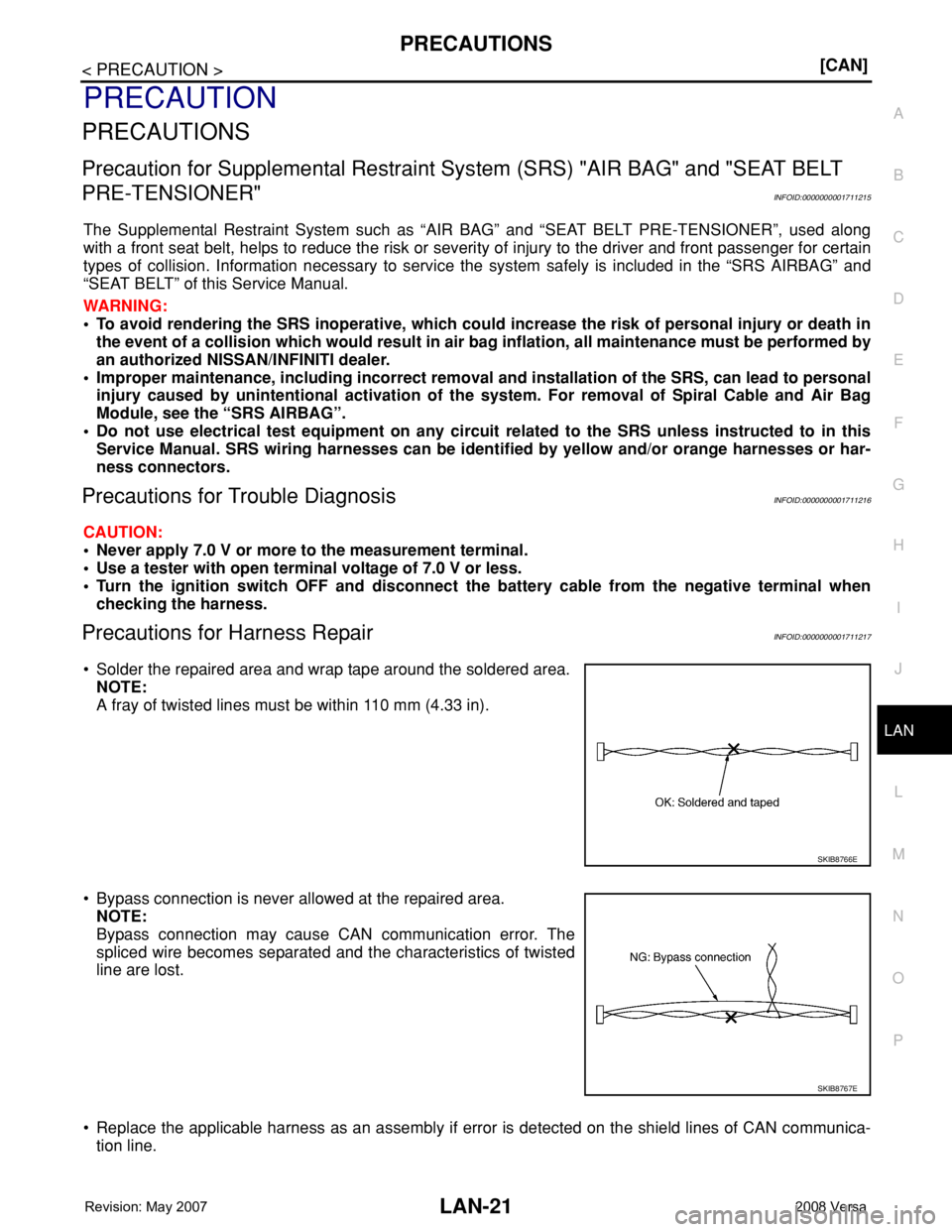
• Solder the repaired area and wrap tape around the soldered area.
NOTE:
A fray of twisted lines must be within 110 mm (4.33 in).
• Bypass connection is never allowed at the repaired area.
NOTE:
Bypass connection may cause CAN communication error. The
spliced wire becomes separated and the characteristics of twisted
line are lost.
• Replace the applicable harness as an assembly if error is detected on the shield lines of CAN communica-
tion line.
SKIB8766E
SKIB8767E
Page 2654 of 2771
![NISSAN TIIDA 2008 Service Repair Manual SRS-20
< SYMPTOM DIAGNOSIS >
TROUBLE DIAGNOSIS
CONSULT-III Diagnostic Code Chart ("SELF-DIAG [CURRENT]")
Diagnostic item ExplanationRepair order
Recheck SRS at each replacement
NO DTC IS DETEC](/img/5/57399/w960_57399-2653.png "NISSAN TIIDA 2008 Service Repair Manual SRS-20
< SYMPTOM DIAGNOSIS >
TROUBLE DIAGNOSIS
CONSULT-III Diagnostic Code Chart (\"SELF-DIAG [CURRENT]\")
Diagnostic item ExplanationRepair order
Recheck SRS at each replacement
NO DTC IS DETEC")
SRS-20
< SYMPTOM DIAGNOSIS >
TROUBLE DIAGNOSIS
CONSULT-III Diagnostic Code Chart ("SELF-DIAG [CURRENT]")
Diagnostic item ExplanationRepair order
Recheck SRS at each replacement
NO DTC IS DETECTEDMalfunction is indicat-
ed by the “AIR BAG”
warning lamp in User
mode.Low battery voltage (Less than 9V) 1. Go to SC-4
2. Go to "DIAGNOSTIC PROCE-
DURE 3" .
“SELF-DIAG [PAST]” memory might
not be erased.Go to "DIAGNOSTIC PROCEDURE 4"
.
Intermittent malfunction has been
detected in the past.Go to "DIAGNOSTIC PROCEDURE 5"
.
No malfunction is detected in User mode. —
DRIVER AIRBAG MODULE
[OPEN]
[B1049] or [B1054]Driver air bag module circuit is open (including the spiral ca-
ble).1. Visually check the wiring harness
connection.
2. Replace the harness if it has visi-
ble damage.
3. Replace driver air bag module.
4. Replace the spiral cable.
5. Replace the air bag diagnosis
sensor unit.
6. Replace the related harness. DRIVER AIRBAG MODULE
[VB-SHORT]
[B1050] or [B1055]Driver air bag module circuit is shorted to some power supply
circuit (including the spiral cable).
DRIVER AIRBAG MODULE
[GND-SHORT]
[B1051] or [B1056]Driver air bag module circuit is shorted to ground (including
the spiral cable).
DRIVER AIRBAG MODULE
[SHORT]
[B1052] or [B1057]Driver air bag module circuits are shorted to each other.
ASSIST A/B MODULE
[OPEN]
[B1065] or [B1070]Front passenger air bag module circuit is open. 1. Visually check the wiring harness
connection.
2. Replace the harness if it has visi-
ble damage.
3. Replace front passenger air bag
module.
4. Replace the air bag diagnosis
sensor unit.
5. Replace the related harness. ASSIST A/B MODULE
[VB-SHORT]
[B1066] or [B1071]Front passenger air bag module circuit is shorted to some
power supply circuit.
ASSIST A/B MODULE
[GND-SHORT]
[B1067] or [B1072]Front passenger air bag module circuit is shorted to ground.
ASSIST A/B MODULE
[SHORT]
[B1068] or [B1073]Front passenger air bag module circuits are shorted to each
other.
CRASH ZONE SEN
[UNIT FAIL]
[B1033] or [B1034]
CRASH ZONE SEN
[COMM FAIL]
[B1035]Crash zone sensor 1. Visually check the wiring harness
connection.
2. Replace the harness if it has visi-
ble damage.
3. Replace the crash zone sensor.
4. Replace the air bag diagnosis
sensor unit.
5. Replace the related harness.
SIDE MODULE LH
[OPEN]
[B1134]Front LH side air bag module circuit is open. 1. Visually check the wiring harness
connection.
2. Replace the harness if it has visi-
ble damage.
3. Replace front LH seat back as-
sembly (front LH side air bag
module).
4. Replace the air bag diagnosis
sensor unit.
5. Replace the related harness. SIDE MODULE LH
[VB-SHORT]
[B1135]Front LH side air bag module circuit is shorted to some power
supply circuit.
SIDE MODULE LH
[GND-SHORT]
[B1136]Front LH side air bag module circuit is shorted to ground.
SIDE MODULE LH
[SHORT]
[B1137]Front LH side air bag module circuits are shorted to each oth-
er.
Page 2658 of 2771

SRS-24
< SYMPTOM DIAGNOSIS >
TROUBLE DIAGNOSIS
2. Touch “TROUBLE DIAG RECORD”.
NOTE:
With “TROUBLE DIAG RECORD”, diagnosis results previously erased by a reset operation can be
displayed.
3. Diagnostic code is displayed on “TROUBLE DIAG RECORD”.
4. Touch “PRINT”.
5. Compare diagnostic codes to "CONSULT-III Diagnostic Code Chart ("SELF-DIAG [PAST]" or "TROUBLE
DIAG RECORD")".
6. Touch “BACK” key of CONSULT-III until “SELECT SYSTEM” appears.
7. Turn ignition switch OFF, then turn off and disconnect CONSULT-III, and both battery cables.
8. Repair the system as outlined by the “Repair order” in “Intermittent Malfunction Diagnostic Code Chart”,
that corresponds to the self-diagnostic result. For replacement procedure of component parts, refer to the
Removal and Installation procedure for the appropriate component.
9. Go to "DIAGNOSTIC PROCEDURE 3", for final checking.
CONSULT-III Diagnostic Code Chart ("SELF-DIAG [PAST]" or "TROUBLE DIAG RECORD")
Diagnostic item ExplanationRepair order
Recheck SRS at each replacement
NO DTC IS DETECTEDWhen malfunction is
indicated by the “AIR
BAG” warning lamp in
User mode.• Low battery voltage (Less than 9V) • Go to "DIAGNOSTIC PROCEDURE
3" .
• Self-diagnostic result “SELF-DIAG
[PAST]” (previously stored in the
memory) might not be erased after
repair.
• Intermittent malfunction has been
detected in the past.• Go to "DIAGNOSTIC PROCEDURE
4" .
• Go to "DIAGNOSTIC PROCEDURE
5" .
• No malfunction is detected. —
DRIVER AIRBAG MODULE
[OPEN]
[B1049] or [B1054]Driver air bag module circuit is open (including the spiral ca-
ble).1. Visually check the wiring harness
connection.
2. Replace the harness if it has visi-
ble damage.
3. Replace driver air bag module.
4. Replace the spiral cable.
5. Replace the air bag diagnosis
sensor unit.
6. Replace the related harness. DRIVER AIRBAG MODULE
[VB-SHORT]
[B1050] or [B1055]Driver air bag module circuit is shorted to some power supply
circuit (including the spiral cable).
DRIVER AIRBAG MODULE
[GND-SHORT]
[B1051] or [B1056]Driver air bag module circuit is shorted to ground (including
the spiral cable).
DRIVER AIRBAG MODULE
[SHORT]
[B1052] or [B1057]Driver air bag module circuits are shorted to each other.
ASSIST A/B MODULE
[OPEN]
[B1065] or [B1070]Front passenger air bag module circuit is open. 1. Visually check the wiring harness
connection.
2. Replace the harness if it has visi-
ble damage.
3. Replace front passenger air bag
module.
4. Replace the air bag diagnosis
sensor unit.
5. Replace the related harness. ASSIST A/B MODULE
[VB-SHORT]
[B1066] or [B1071]Front passenger air bag module circuit is shorted to some
power supply circuit.
ASSIST A/B MODULE
[GND-SHORT]
[B1067] or [B1072]Front passenger air bag module circuit is shorted to ground.
ASSIST A/B MODULE
[SHORT]
[B1068] or [B1073]Front passenger air bag module circuits are shorted to each
other.