brakes NISSAN TIIDA 2008 Service Repair Manual
[x] Cancel search | Manufacturer: NISSAN, Model Year: 2008, Model line: TIIDA, Model: NISSAN TIIDA 2008Pages: 2771, PDF Size: 60.61 MB
Page 1 of 2771
-1
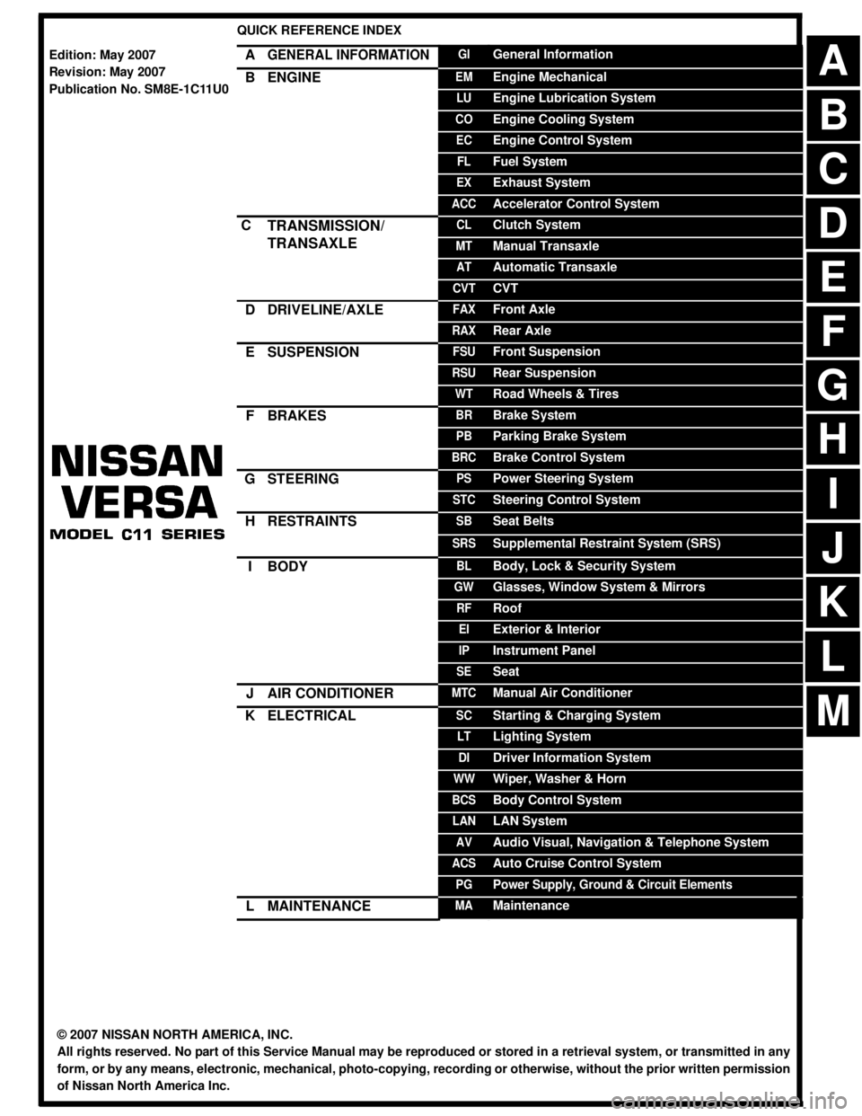
QUICK REFERENCE INDEX
AGENERAL INFORMATIONGIGeneral Information
BENGINEEMEngine Mechanical
LUEngine Lubrication System
COEngine Cooling System
ECEngine Control System
FLFuel System
EXExhaust System
ACCAccelerator Control System
CTRANSMISSION/
TRANSAXLECLClutch System
MTManual Transaxle
ATAutomatic Transaxle
CVTCVT
DDRIVELINE/AXLEFAXFront Axle
RAXRear Axle
ESUSPENSIONFSUFront Suspension
RSURear Suspension
WTRoad Wheels & Tires
FBRAKESBRBrake System
PBParking Brake System
BRCBrake Control System
GSTEERINGPSPower Steering System
STCSteering Control System
HRESTRAINTSSBSeat Belts
SRSSupplemental Restraint System (SRS)
IBODYBLBody, Lock & Security System
GWGlasses, Window System & Mirrors
RFRoof
EIExterior & Interior
IPInstrument Panel
SESeat
JAIR CONDITIONERMTCManual Air Conditioner
KELECTRICALSCStarting & Charging System
LTLighting System
DIDriver Information System
WWWiper, Washer & Horn
BCSBody Control System
LANLAN System
AVAudio Visual, Navigation & Telephone System
ACSAuto Cruise Control System
PGPower Supply, Ground & Circuit Elements
LMAINTENANCEMAMaintenance
Edition: May 2007
Revision: May 2007
Publication No. SM8E-1C11U0
B
D
© 2007 NISSAN NORTH AMERICA, INC.
All rights reserved. No part of this Service Manual may be reproduced or stored in a retrieval system, or transmitted in any
form, or by any means, electronic, mechanical, photo-copying, recording or otherwise, without the prior written permission
of Nissan North America Inc.
A
C
E
F
G
H
I
J
K
L
M
Page 16 of 2771

AT-4
Diagnosis Procedure .............................................210
KEY INTERLOCK CABLE ...............................213
Removal and Installation .......................................213
ON-VEHICLE SERVICE ..................................216
Control Valve Assembly and Accumulators ...........216
Park/Neutral Position (PNP) Switch ......................219
Revolution Sensor .................................................221
Turbine Revolution Sensor (Power Train Revolu-
tion Sensor) ...........................................................
222
Differential Side Oil Seal ........................................223
AIR BREATHER HOSE ...................................225
Removal and Installation .......................................225
TRANSAXLE ASSEMBLY ..............................226
Removal and Installation .......................................226
OVERHAUL .....................................................230
Component ............................................................230
Oil Channel ............................................................237
Location of Adjusting Shims, Needle Bearings and
Thrust Washers .....................................................
238
Location of Snap Rings .........................................239
DISASSEMBLY ...............................................240
Disassembly ..........................................................240
REPAIR FOR COMPONENT PARTS ..............257
Manual Shaft .........................................................257
Oil Pump ................................................................260
Control Valve Assembly ........................................263
Control Valve Upper Body .....................................272
Control Valve Lower Body .....................................276
Reverse Clutch ......................................................279
High Clutch ............................................................284
Forward and Overrun Clutches .............................288
Low & Reverse Brake ............................................295
Rear Internal Gear and Forward Clutch Hub .........299
Output Shaft, Output Gear, Idler Gear, Reduction
Pinion Gear and Bearing Retainer .........................
302
Band Servo Piston Assembly ................................307
Final Drive .............................................................313
ASSEMBLY ......................................................318
Assembly (1) .........................................................318
Adjustment (1) .......................................................319
Assembly (2) .........................................................325
Adjustment (2) .......................................................330
Assembly (3) .........................................................333
SERVICE DATA AND SPECIFICATIONS
(SDS) ................................................................
341
General Specification ............................................341
Vehicle Speed at Which Gear Shifting Occurs .....341
Vehicle Speed at When Lock-up Occurs/Releases
.
341
Stall Speed ............................................................341
Line Pressure ........................................................341
Adjusting shims, Needle Bearings, Thrust Wash-
ers and Snap Rings ..............................................
341
Control Valves .......................................................343
Accumulator ..........................................................343
Clutches and Brakes .............................................343
Final Drive .............................................................345
Planetary Carrier ...................................................345
Oil Pump ...............................................................345
Input Shaft .............................................................345
Reduction Pinion Gear ..........................................345
Band Servo ...........................................................345
Output Shaft ..........................................................346
Bearing Retainer ...................................................346
Total End Play .......................................................346
Reverse Clutch End Play ......................................346
Removal and Installation .......................................346
Shift Solenoid Valves ............................................346
Solenoid Valves ....................................................346
A/T Fluid Temperature Sensor ..............................347
Revolution Sensor .................................................347
Dropping Resistor .................................................347
Turbine Revolution Sensor (Power Train Revolu-
tion Sensor) ...........................................................
347
Page 55 of 2771
TROUBLE DIAGNOSIS
AT-43
< SERVICE INFORMATION >
D
E
F
G
H
I
J
K
L
MA
B
AT
N
O
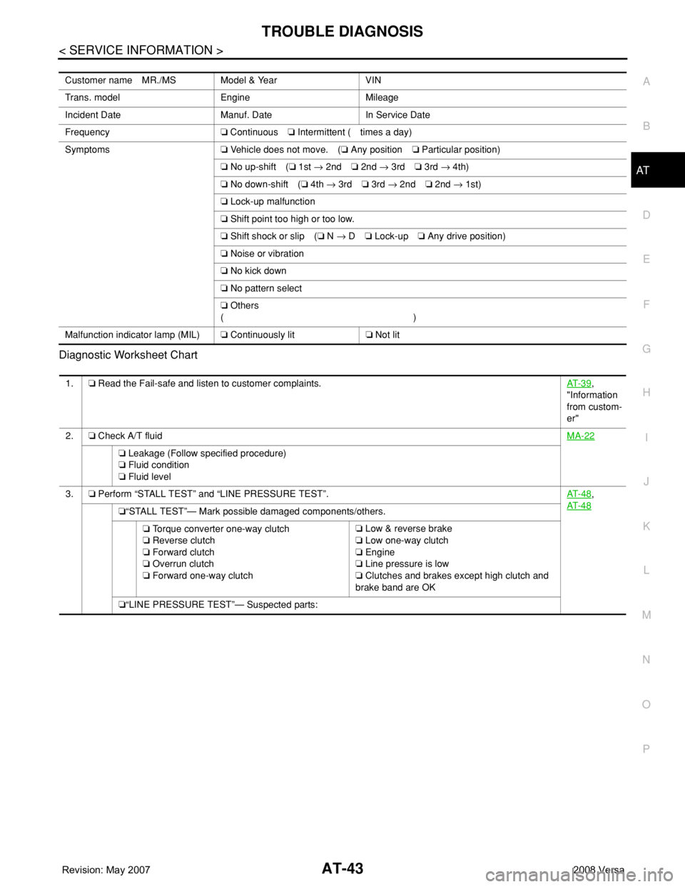
P Diagnostic Worksheet Chart
Customer name MR./MS Model & Year VIN
Trans. model Engine Mileage
Incident Date Manuf. Date In Service Date
Frequency❏ Continuous❏ Intermittent ( times a day)
Symptoms❏ Vehicle does not move. (❏ Any position❏ Particular position)
❏ No up-shift (❏ 1st → 2nd❏ 2nd → 3rd❏ 3rd → 4th)
❏ No down-shift (❏ 4th → 3rd❏ 3rd → 2nd❏ 2nd → 1st)
❏ Lock-up malfunction
❏ Shift point too high or too low.
❏ Shift shock or slip (❏ N → D❏ Lock-up❏ Any drive position)
❏ Noise or vibration
❏ No kick down
❏ No pattern select
❏ Others
()
Malfunction indicator lamp (MIL)❏ Continuously lit❏ Not lit
1.❏ Read the Fail-safe and listen to customer complaints.AT- 3 9,
"Information
from custom-
er"
2.❏ Check A/T fluidMA-22
❏ Leakage (Follow specified procedure)
❏ Fluid condition
❏ Fluid level
3.❏ Perform “STALL TEST” and “LINE PRESSURE TEST”.AT- 4 8
,
AT- 4 8
❏“STALL TEST”— Mark possible damaged components/others.
❏ Torque converter one-way clutch
❏ Reverse clutch
❏ Forward clutch
❏ Overrun clutch
❏ Forward one-way clutch❏ Low & reverse brake
❏ Low one-way clutch
❏ Engine
❏ Line pressure is low
❏ Clutches and brakes except high clutch and
brake band are OK
❏“LINE PRESSURE TEST”— Suspected parts:
Page 78 of 2771
AT-66
< SERVICE INFORMATION >
TROUBLE DIAGNOSIS
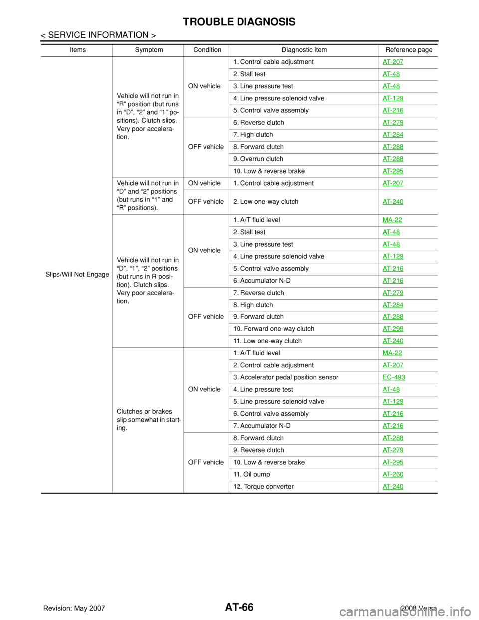
Slips/Will Not EngageVehicle will not run in
“R” position (but runs
in “D”, “2” and “1” po-
sitions). Clutch slips.
Very poor accelera-
tion.ON vehicle1. Control cable adjustmentAT- 2 0 7
2. Stall testAT- 4 8
3. Line pressure testAT- 4 8
4. Line pressure solenoid valveAT- 1 2 9
5. Control valve assemblyAT- 2 1 6
OFF vehicle6. Reverse clutchAT- 2 7 9
7. High clutchAT- 2 8 4
8. Forward clutchAT- 2 8 8
9. Overrun clutchAT- 2 8 8
10. Low & reverse brakeAT- 2 9 5
Vehicle will not run in
“D” and “2” positions
(but runs in “1” and
“R” positions).ON vehicle 1. Control cable adjustmentAT- 2 0 7
OFF vehicle 2. Low one-way clutchAT- 2 4 0
Vehicle will not run in
“D”, “1”, “2” positions
(but runs in R posi-
tion). Clutch slips.
Very poor accelera-
tion.ON vehicle1. A/T fluid levelMA-22
2. Stall testAT- 4 8
3. Line pressure testAT- 4 8
4. Line pressure solenoid valveAT- 1 2 9
5. Control valve assemblyAT- 2 1 6
6. Accumulator N-DAT- 2 1 6
OFF vehicle7. Reverse clutchAT- 2 7 9
8. High clutchAT- 2 8 4
9. Forward clutchAT- 2 8 8
10. Forward one-way clutchAT- 2 9 9
11. Low one-way clutchAT- 2 4 0
Clutches or brakes
slip somewhat in start-
ing.ON vehicle1. A/T fluid levelMA-22
2. Control cable adjustmentAT- 2 0 7
3. Accelerator pedal position sensorEC-493
4. Line pressure testAT- 4 8
5. Line pressure solenoid valveAT- 1 2 9
6. Control valve assemblyAT- 2 1 6
7. Accumulator N-DAT- 2 1 6
OFF vehicle8. Forward clutchAT- 2 8 8
9. Reverse clutchAT- 2 7 9
10. Low & reverse brakeAT- 2 9 5
11 . O i l p u m pAT- 2 6 0
12. Torque converterAT- 2 4 0
Items Symptom Condition Diagnostic item Reference page
Page 293 of 2771
REPAIR FOR COMPONENT PARTS
AT-281
< SERVICE INFORMATION >
D
E
F
G
H
I
J
K
L
MA
B
AT
N
O
P
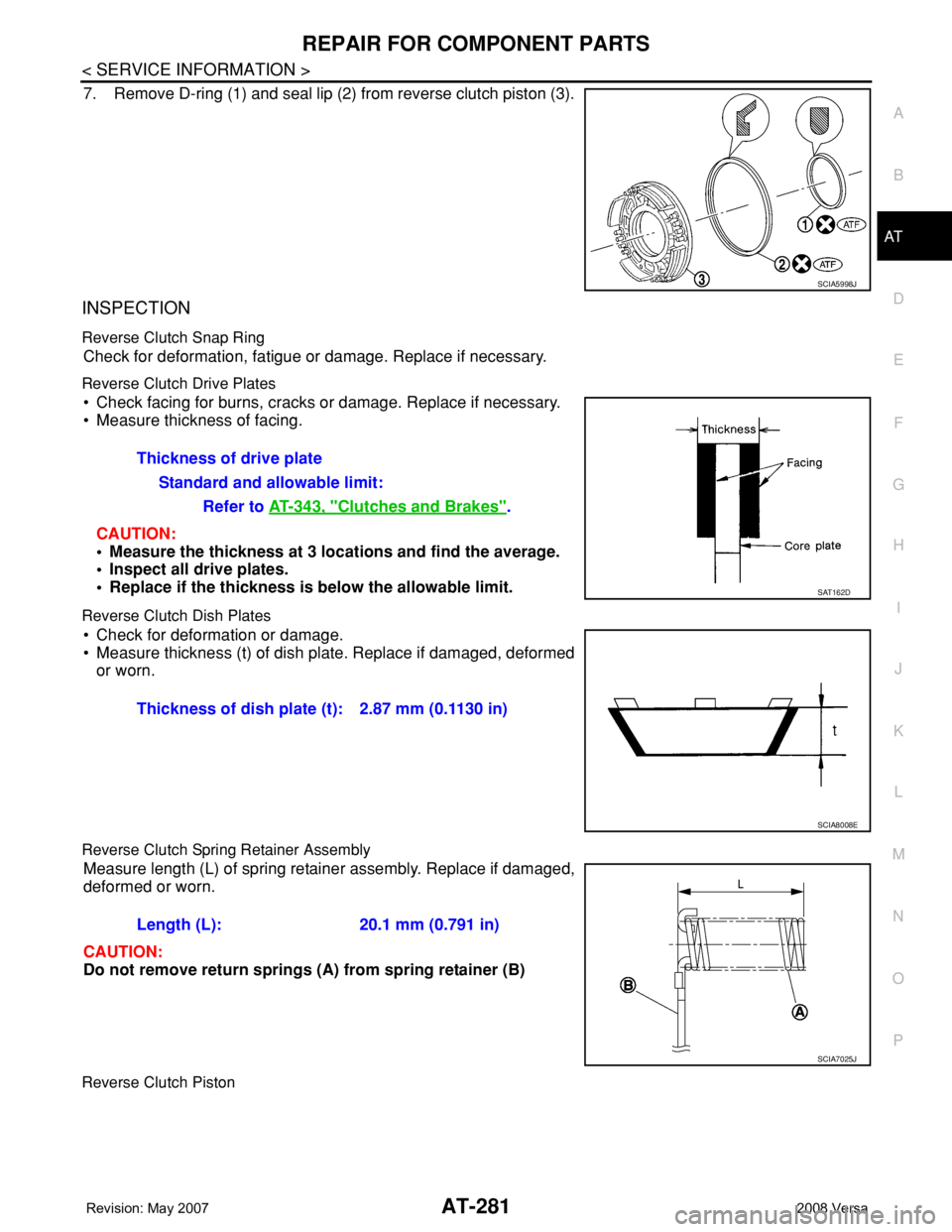
7. Remove D-ring (1) and seal lip (2) from reverse clutch piston (3).
INSPECTION
Reverse Clutch Snap Ring
Check for deformation, fatigue or damage. Replace if necessary.
Reverse Clutch Drive Plates
• Check facing for burns, cracks or damage. Replace if necessary.
• Measure thickness of facing.
CAUTION:
• Measure the thickness at 3 locations and find the average.
• Inspect all drive plates.
• Replace if the thickness is below the allowable limit.
Reverse Clutch Dish Plates
• Check for deformation or damage.
• Measure thickness (t) of dish plate. Replace if damaged, deformed
or worn.
Reverse Clutch Spring Retainer Assembly
Measure length (L) of spring retainer assembly. Replace if damaged,
deformed or worn.
CAUTION:
Do not remove return springs (A) from spring retainer (B)
Reverse Clutch Piston
SCIA5998J
Thickness of drive plate
Standard and allowable limit:
Refer to AT-343, "
Clutches and Brakes".
SAT162D
Thickness of dish plate (t): 2.87 mm (0.1130 in)
SCIA8008E
Length (L): 20.1 mm (0.791 in)
SCIA7025J
Page 296 of 2771
AT-284
< SERVICE INFORMATION >
REPAIR FOR COMPONENT PARTS
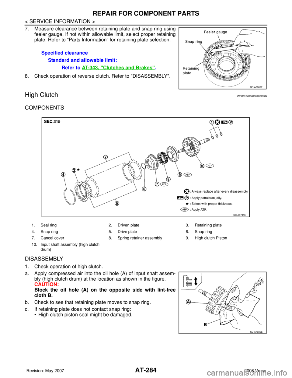
7. Measure clearance between retaining plate and snap ring using
feeler gauge. If not within allowable limit, select proper retaining
plate. Refer to “Parts Information” for retaining plate selection.
8. Check operation of reverse clutch. Refer to "DISASSEMBLY".
High ClutchINFOID:0000000001703384
COMPONENTS
DISASSEMBLY
1. Check operation of high clutch.
a. Apply compressed air into the oil hole (A) of input shaft assem-
bly (high clutch drum) at the location as shown in the figure.
CAUTION:
Block the oil hole (A) on the opposite side with lint-free
cloth B.
b. Check to see that retaining plate moves to snap ring.
c. If retaining plate does not contact snap ring:
• High clutch piston seal might be damaged.Specified clearance
Standard and allowable limit:
Refer to AT-343, "
Clutches and Brakes".
SCIA8009E
1. Seal ring 2. Driven plate 3. Retaining plate
4. Snap ring 5. Drive plate 6. Snap ring
7. Cancel cover 8. Spring retainer assembly 9. High clutch Piston
10. Input shaft assembly (high clutch
drum)
SCIA6741E
SCIA7032E
Page 298 of 2771
AT-286
< SERVICE INFORMATION >
REPAIR FOR COMPONENT PARTS
INSPECTION
High Clutch Snap Ring
Check for deformation, fatigue or damage. Replace if necessary.
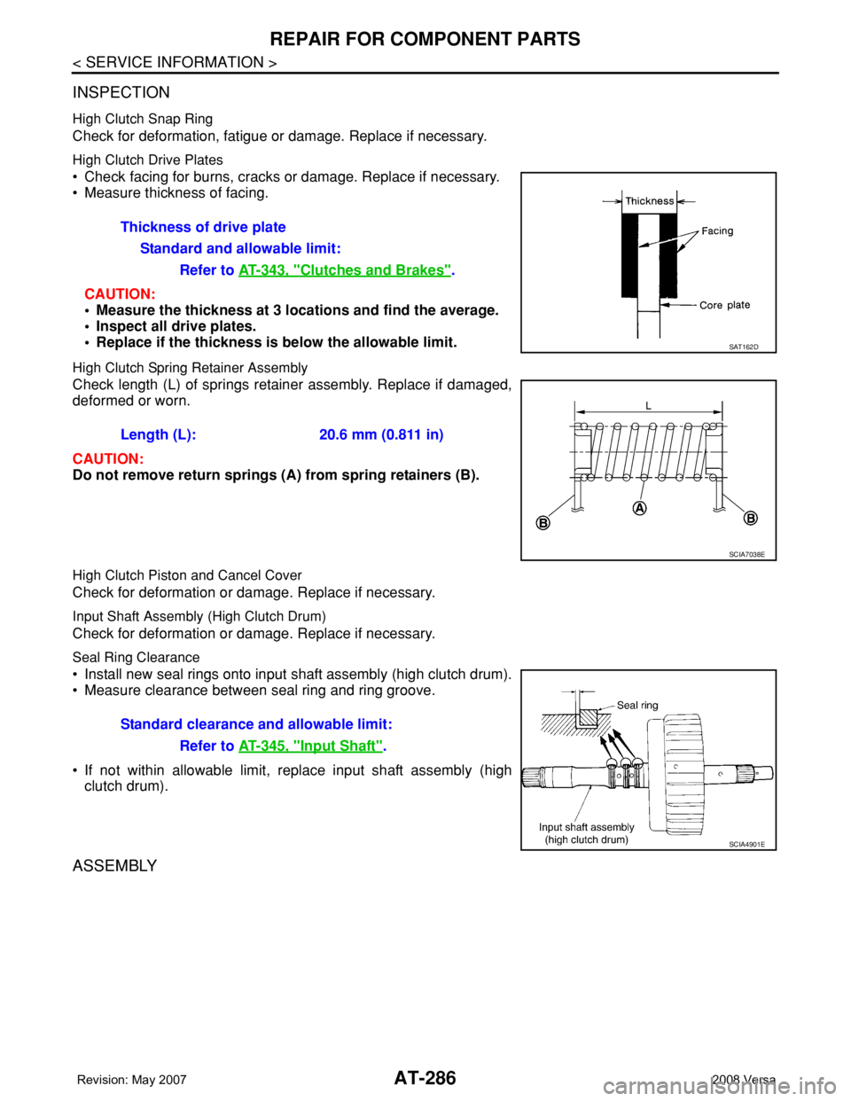
High Clutch Drive Plates
• Check facing for burns, cracks or damage. Replace if necessary.
• Measure thickness of facing.
CAUTION:
• Measure the thickness at 3 locations and find the average.
• Inspect all drive plates.
• Replace if the thickness is below the allowable limit.
High Clutch Spring Retainer Assembly
Check length (L) of springs retainer assembly. Replace if damaged,
deformed or worn.
CAUTION:
Do not remove return springs (A) from spring retainers (B).
High Clutch Piston and Cancel Cover
Check for deformation or damage. Replace if necessary.
Input Shaft Assembly (High Clutch Drum)
Check for deformation or damage. Replace if necessary.
Seal Ring Clearance
• Install new seal rings onto input shaft assembly (high clutch drum).
• Measure clearance between seal ring and ring groove.
• If not within allowable limit, replace input shaft assembly (high
clutch drum).
ASSEMBLY
Thickness of drive plate
Standard and allowable limit:
Refer to AT-343, "
Clutches and Brakes".
SAT162D
Length (L): 20.6 mm (0.811 in)
SCIA7038E
Standard clearance and allowable limit:
Refer to AT-345, "
Input Shaft".
SCIA4901E
Page 300 of 2771
AT-288
< SERVICE INFORMATION >
REPAIR FOR COMPONENT PARTS
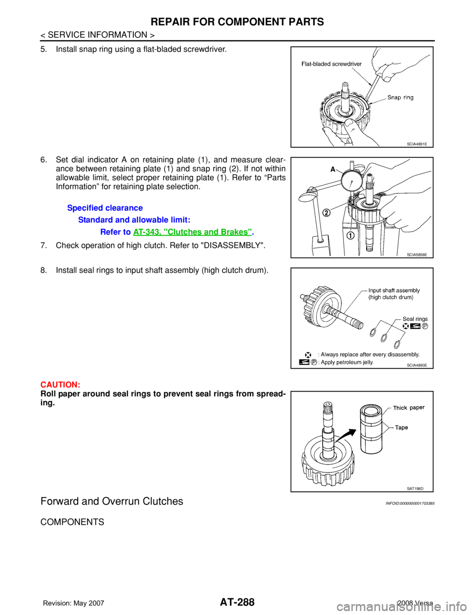
5. Install snap ring using a flat-bladed screwdriver.
6. Set dial indicator A on retaining plate (1), and measure clear-
ance between retaining plate (1) and snap ring (2). If not within
allowable limit, select proper retaining plate (1). Refer to “Parts
Information” for retaining plate selection.
7. Check operation of high clutch. Refer to "DISASSEMBLY".
8. Install seal rings to input shaft assembly (high clutch drum).
CAUTION:
Roll paper around seal rings to prevent seal rings from spread-
ing.
Forward and Overrun ClutchesINFOID:0000000001703385
COMPONENTS
SCIA4891E
Specified clearance
Standard and allowable limit:
Refer to AT-343, "
Clutches and Brakes".
SCIA5858E
SCIA4890E
SAT198D
Page 303 of 2771
REPAIR FOR COMPONENT PARTS
AT-291
< SERVICE INFORMATION >
D
E
F
G
H
I
J
K
L
MA
B
AT
N
O
P
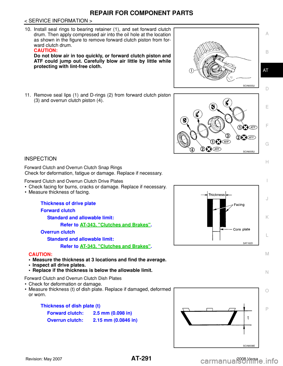
10. Install seal rings to bearing retainer (1), and set forward clutch
drum. Then apply compressed air into the oil hole at the location
as shown in the figure to remove forward clutch piston from for-
ward clutch drum.
CAUTION:
Do not blow air in too quickly, or forward clutch piston and
ATF could jump out. Carefully blow air little by little while
protecting with lint-free cloth.
11. Remove seal lips (1) and D-rings (2) from forward clutch piston
(3) and overrun clutch piston (4).
INSPECTION
Forward Clutch and Overrun Clutch Snap Rings
Check for deformation, fatigue or damage. Replace if necessary.
Forward Clutch and Overrun Clutch Drive Plates
• Check facing for burns, cracks or damage. Replace if necessary.
• Measure thickness of facing.
CAUTION:
• Measure the thickness at 3 locations and find the average.
• Inspect all drive plates.
• Replace if the thickness is below the allowable limit.
Forward Clutch and Overrun Clutch Dish Plates
• Check for deformation or damage.
• Measure thickness (t) of dish plate. Replace if damaged, deformed
or worn.
SCIA6003J
SCIA6005J
Thickness of drive plate
Forward clutch
Standard and allowable limit:
Refer to AT-343, "
Clutches and Brakes".
Overrun clutch
Standard and allowable limit:
Refer to AT-343, "
Clutches and Brakes".SAT162D
Thickness of dish plate (t)
Forward clutch: 2.5 mm (0.098 in)
Overrun clutch: 2.15 mm (0.0846 in)
SCIA8008E
Page 306 of 2771
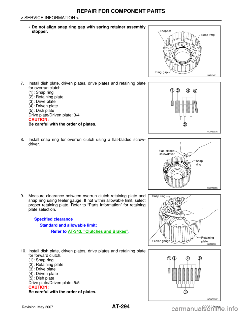
AT-294
< SERVICE INFORMATION >
REPAIR FOR COMPONENT PARTS
• Do not align snap ring gap with spring retainer assembly
stopper.
7. Install dish plate, driven plates, drive plates and retaining plate
for overrun clutch.
(1): Snap ring
(2): Retaining plate
(3): Drive plate
(4): Driven plate
(5): Dish plate
Drive plate/Driven plate: 3/4
CAUTION:
Be careful with the order of plates.
8. Install snap ring for overrun clutch using a flat-bladed screw-
driver.
9. Measure clearance between overrun clutch retaining plate and
snap ring using feeler gauge. If not within allowable limit, select
proper retaining plate. Refer to “Parts Information” for retaining
plate selection.
10. Install dish plate, driven plates, drive plates and retaining plate
for forward clutch.
(1): Snap ring
(2): Retaining plate
(3): Drive plate
(4): Driven plate
(5): Dish plate
Drive plate/Driven plate: 5/5
CAUTION:
Be careful with the order of plates.
SAT134F
SCIA5993E
SCIA4895E
Specified clearance
Standard and allowable limit:
Refer to AT-343, "
Clutches and Brakes".
SAT227D
SCIA5992E