door cover removal NISSAN TIIDA 2008 Service Repair Manual
[x] Cancel search | Manufacturer: NISSAN, Model Year: 2008, Model line: TIIDA, Model: NISSAN TIIDA 2008Pages: 2771, PDF Size: 60.61 MB
Page 435 of 2771

BL-1
BODY
C
D
E
F
G
H
J
K
L
M
SECTION BL
A
B
BL
N
O
P
CONTENTS
BODY, LOCK & SECURITY SYSTEM
SERVICE INFORMATION ............................4
PRECAUTIONS ...................................................4
Precaution for Supplemental Restraint System
(SRS) "AIR BAG" and "SEAT BELT PRE-TEN-
SIONER" ...................................................................
4
Precaution Necessary for Steering Wheel Rota-
tion After Battery Disconnect .....................................
4
Precaution for Procedure without Cowl Top Cover ......5
Precaution for Work ..................................................5
PREPARATION ...................................................6
Special Service Tool .................................................6
Commercial Service Tool ..........................................6
SQUEAK AND RATTLE TROUBLE DIAG-
NOSES ................................................................
7
Work Flow .................................................................7
Generic Squeak and Rattle Troubleshooting ............9
Diagnostic Worksheet .............................................11
HOOD .................................................................13
Fitting Adjustment ...................................................13
Removal and Installation .........................................14
Removal and Installation of Hood Lock Control ......15
Hood Lock Control Inspection .................................17
RADIATOR CORE SUPPORT ...........................19
Removal and Installation .........................................19
FRONT FENDER ................................................21
Removal and Installation .........................................21
POWER DOOR LOCK SYSTEM ........................22
Component Parts and Harness Connector Loca-
tion ..........................................................................
22
System Description .................................................22
CAN Communication System Description ...............24
Schematic ...............................................................25
Wiring Diagram - D/LOCK - .....................................26
Schematic ...............................................................30
Wiring Diagram - D/LOCK - .....................................31
Terminal and Reference Value for BCM ..................35
Work Flow ................................................................35
CONSULT-III Function (BCM) .................................36
Trouble Diagnosis Symptom Chart ..........................37
BCM Power Supply and Ground Circuit ..................37
Door Switch Check (Hatchback) ..............................37
Door Switch Check (Sedan) ....................................40
Key Switch (Insert) Check .......................................41
Door Lock and Unlock Switch Check ......................42
Front Door Lock Assembly LH (Actuator) Check .....45
Door Lock Actuator Check (Front RH and Rear
LH/RH) .....................................................................
46
Front Door Key Cylinder Switch LH Check ..............47
Passenger Select Unlock Relay Circuit Inspection
(With Intelligent Key) ...............................................
48
REMOTE KEYLESS ENTRY SYSTEM .............51
Component Parts and Harness Connector Loca-
tion ...........................................................................
51
System Description ..................................................51
CAN Communication System Description ...............53
Schematic ................................................................54
Wiring Diagram - KEYLES - ....................................55
Terminal and Reference Value for BCM ..................57
How to Perform Trouble Diagnosis ..........................57
Preliminary Check ...................................................58
CONSULT-III Function (BCM) .................................58
Work Flow ................................................................59
Trouble Diagnosis Symptom Chart ..........................60
Keyfob Battery and Function Check ........................61
ACC Switch Check ..................................................62
Door Switch Check (Hatchback) ..............................62
Door Switch Check (Sedan) ....................................65
Key Switch (Insert) Check .......................................66
Hazard Function Check ...........................................67
Horn Function Check ...............................................67
Interior Lamp and Ignition Keyhole Illumination
Function Check ........................................................
68
Remote Keyless Entry Receiver Check ...................68
Keyfob Function (Lock) Check ................................71
Keyfob Function (Unlock) Check .............................71
Page 443 of 2771

SQUEAK AND RATTLE TROUBLE DIAGNOSES
BL-9
< SERVICE INFORMATION >
C
D
E
F
G
H
J
K
L
MA
B
BL
N
O
P
SILICONE GREASE
Used instead of UHMW tape that will be visible or not fit.
Note: Will only last a few months.
SILICONE SPRAY
Use when grease cannot be applied.
DUCT TAPE
Use to eliminate movement.
CONFIRM THE REPAIR
Confirm that the cause of a noise is repaired by test driving the vehicle. Operate the vehicle under the same
conditions as when the noise originally occurred. Refer to the notes on the Diagnostic Worksheet.
Generic Squeak and Rattle TroubleshootingINFOID:0000000001703945
Refer to Table of Contents for specific component removal and installation information.
INSTRUMENT PANEL
Most incidents are caused by contact and movement between:
1. The cluster lid A and instrument panel
2. Acrylic lens and combination meter housing
3. Instrument panel to front pillar garnish
4. Instrument panel to windshield
5. Instrument panel mounting pins
6. Wiring harnesses behind the combination meter
7. A/C defroster duct and duct joint
These incidents can usually be located by tapping or moving the components to duplicate the noise or by
pressing on the components while driving to stop the noise. Most of these incidents can be repaired by apply-
ing felt cloth tape or silicone spray (in hard to reach areas). Urethane pads can be used to insulate wiring har-
ness.
CAUTION:
Do not use silicone spray to isolate a squeak or rattle. If you saturate the area with silicone, you will
not be able to recheck the repair.
CENTER CONSOLE
Components to pay attention to include:
1. Shifter assembly cover to finisher
2. A/C control unit and cluster lid C
3. Wiring harnesses behind audio and A/C control unit
The instrument panel repair and isolation procedures also apply to the center console.
DOORS
Pay attention to the:
1. Finisher and inner panel making a slapping noise
2. Inside handle escutcheon to door finisher
3. Wiring harnesses tapping
4. Door striker out of alignment causing a popping noise on starts and stops
Tapping or moving the components or pressing on them while driving to duplicate the conditions can isolate
many of these incidents. You can usually insulate the areas with felt cloth tape or insulator foam blocks from
the NISSAN Squeak and Rattle Kit (J-43980) to repair the noise.
TRUNK
Trunk noises are often caused by a loose jack or loose items put into the trunk by the owner.
In addition look for:
1. Trunk lid bumpers out of adjustment
2. Trunk lid striker out of adjustment
3. The trunk lid torsion bars knocking together
4. A loose license plate or bracket
Page 1630 of 2771

SQUEAK AND RATTLE TROUBLE DIAGNOSIS
EI-7
< SYMPTOM DIAGNOSIS >
C
D
E
F
G
H
J
K
L
MA
B
EI
N
O
P
The following materials, not found in the kit, can also be used to repair squeaks and rattles.
UHMW (TEFLON) TAPE
Insulates where slight movement is present. Ideal for instrument panel applications.
SILICONE GREASE
Used in place of UHMW tape that will be visible or not fit.
Note: Will only last a few months.
SILICONE SPRAY
Use when grease cannot be applied.
DUCT TAPE
Use to eliminate movement.
CONFIRM THE REPAIR
Confirm that the cause of a noise is repaired by test driving the vehicle. Operate the vehicle under the same
conditions as when the noise originally occurred. Refer to the notes on the Diagnostic Worksheet.
Generic Squeak and Rattle TroubleshootingINFOID:0000000001704215
Refer to Table of Contents for specific component removal and installation information.
INSTRUMENT PANEL
Most incidents are caused by contact and movement between:
1. The cluster lid A and instrument panel
2. Acrylic lens and combination meter housing
3. Instrument panel to front pillar garnish
4. Instrument panel to windshield
5. Instrument panel pins
6. Wiring harnesses behind the combination meter
7. A/C defroster duct and duct joint
These incidents can usually be located by tapping or moving the components to duplicate the noise or by
pressing on the components while driving to stop the noise. Most of these incidents can be repaired by apply-
ing felt cloth tape or silicone spray (in hard to reach areas). Urethane pads can be used to insulate wiring har-
ness.
CAUTION:
Do not use silicone spray to isolate a squeak or rattle. If you saturate the area with silicone, you will
not be able to recheck the repair.
CENTER CONSOLE
Components to pay attention to include:
1. Shifter assembly cover to finisher
2. A/C control unit and cluster lid C
3. Wiring harnesses behind audio and A/C control unit
The instrument panel repair and isolation procedures also apply to the center console.
DOORS
Pay attention to the:
1. Finisher and inner panel making a slapping noise
2. Inside handle escutcheon to door finisher
3. Wiring harnesses tapping
4. Door striker out of alignment causing a popping noise on starts and stops
Tapping or moving the components or pressing on them while driving to duplicate the conditions can isolate
many of these incidents. You can usually insulate the areas with felt cloth tape or insulator foam blocks from
the NISSAN Squeak and Rattle Kit (J-43980) to repair the noise.
TRUNK
Trunk noises are often caused by a loose jack or loose items put into the trunk by the owner.
In addition look for:
1. Trunk lid bumpers out of adjustment
2. Trunk lid striker out of adjustment
Page 1650 of 2771
DOOR OUTSIDE MOLDING
EI-27
< ON-VEHICLE REPAIR >
C
D
E
F
G
H
J
K
L
MA
B
EI
N
O
P
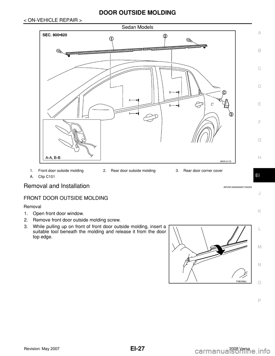
Sedan Models
Removal and InstallationINFOID:0000000001704229
FRONT DOOR OUTSIDE MOLDING
Removal
1. Open front door window.
2. Remove front door outside molding screw.
3. While pulling up on front of front door outside molding, insert a
suitable tool beneath the molding and release it from the door
top edge.
WIIA1411E
1. Front door outside molding 2. Rear door outside molding 3. Rear door corner cover
A. Clip C101
PIIB3386J
Page 1651 of 2771
EI-28
< ON-VEHICLE REPAIR >
DOOR OUTSIDE MOLDING
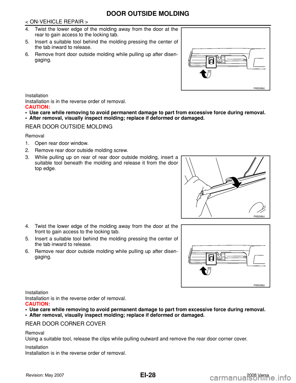
4. Twist the lower edge of the molding away from the door at the
rear to gain access to the locking tab.
5. Insert a suitable tool behind the molding pressing the center of
the tab inward to release.
6. Remove front door outside molding while pulling up after disen-
gaging.
Installation
Installation is in the reverse order of removal.
CAUTION:
• Use care while removing to avoid permanent damage to part from excessive force during removal.
• After removal, visually inspect molding; replace if deformed or damaged.
REAR DOOR OUTSIDE MOLDING
Removal
1. Open rear door window.
2. Remove rear door outside molding screw.
3. While pulling up on rear of rear door outside molding, insert a
suitable tool beneath the molding and release it from the door
top edge.
4. Twist the lower edge of the molding away from the door at the
front to gain access to the locking tab.
5. Insert a suitable tool behind the molding pressing the center of
the tab inward to release.
6. Remove rear door outside molding while pulling up after disen-
gaging.
Installation
Installation is in the reverse order of removal.
CAUTION:
• Use care while removing to avoid permanent damage to part from excessive force during removal.
• After removal, visually inspect molding; replace if deformed or damaged.
REAR DOOR CORNER COVER
Removal
Using a suitable tool, release the clips while pulling outward and remove the rear door corner cover.
Installation
Installation is in the reverse order of removal.
PIIB3388J
PIIB3386J
PIIB3388J
Page 1652 of 2771
CENTER MUD GUARD
EI-29
< ON-VEHICLE REPAIR >
C
D
E
F
G
H
J
K
L
MA
B
EI
N
O
P
CENTER MUD GUARD
Removal and InstallationINFOID:0000000001704230
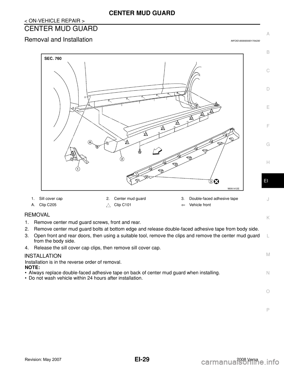
REMOVAL
1. Remove center mud guard screws, front and rear.
2. Remove center mud guard bolts at bottom edge and release double-faced adhesive tape from body side.
3. Open front and rear doors, then using a suitable tool, remove the clips and remove the center mud guard
from the body side.
4. Release the sill cover cap clips, then remove sill cover cap.
INSTALLATION
Installation is in the reverse order of removal.
NOTE:
• Always replace double-faced adhesive tape on back of center mud guard when installing.
• Do not wash vehicle within 24 hours after installation.
1. Sill cover cap 2. Center mud guard 3. Double-faced adhesive tape
A. Clip C205 Clip C101⇐Vehicle front
WIIA1412E
Page 1659 of 2771
EI-36
< ON-VEHICLE REPAIR >
BACK DOOR TRIM
BACK DOOR TRIM
Removal and InstallationINFOID:0000000001704234
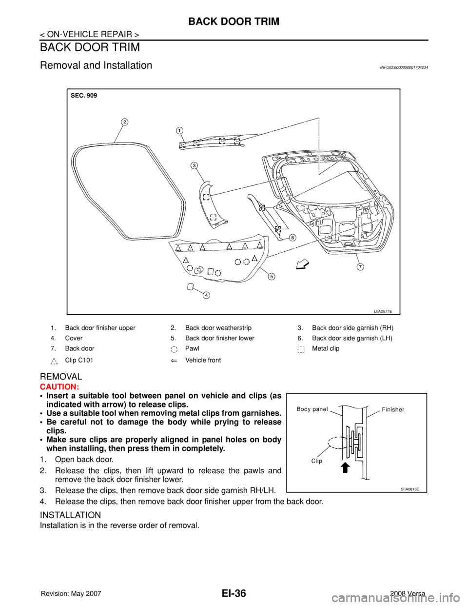
REMOVAL
CAUTION:
• Insert a suitable tool between panel on vehicle and clips (as
indicated with arrow) to release clips.
• Use a suitable tool when removing metal clips from garnishes.
• Be careful not to damage the body while prying to release
clips.
• Make sure clips are properly aligned in panel holes on body
when installing, then press them in completely.
1. Open back door.
2. Release the clips, then lift upward to release the pawls and
remove the back door finisher lower.
3. Release the clips, then remove back door side garnish RH/LH.
4. Release the clips, then remove back door finisher upper from the back door.
INSTALLATION
Installation is in the reverse order of removal.
1. Back door finisher upper 2. Back door weatherstrip 3. Back door side garnish (RH)
4. Cover 5. Back door finisher lower 6. Back door side garnish (LH)
7. Back door Pawl Metal clip
Clip C101⇐Vehicle front
LIIA2577E
SIIA0810E
Page 1667 of 2771
EI-44
< ON-VEHICLE REPAIR >
FLOOR TRIM
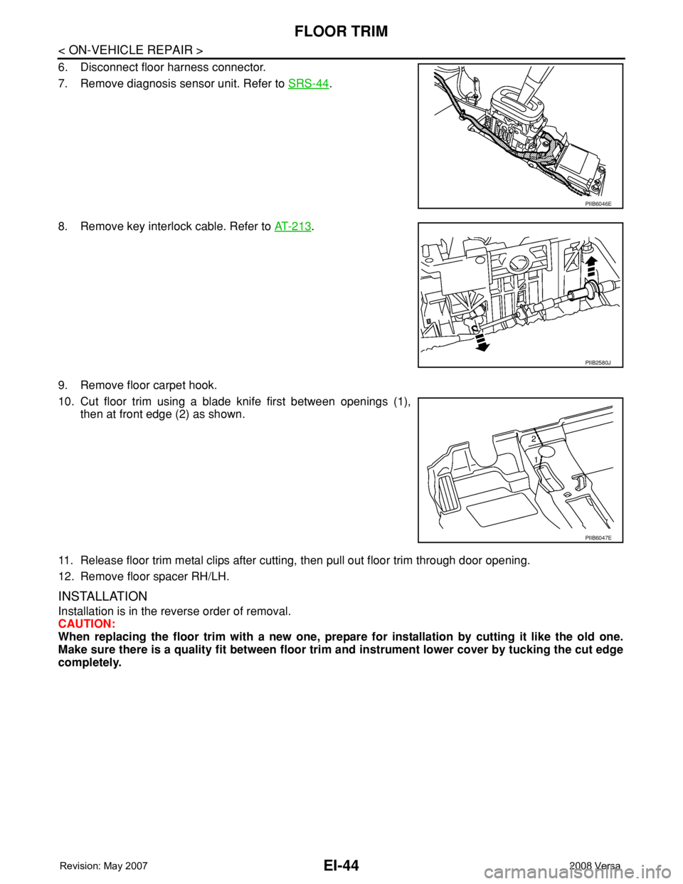
6. Disconnect floor harness connector.
7. Remove diagnosis sensor unit. Refer to SRS-44
.
8. Remove key interlock cable. Refer to AT-213
.
9. Remove floor carpet hook.
10. Cut floor trim using a blade knife first between openings (1),
then at front edge (2) as shown.
11. Release floor trim metal clips after cutting, then pull out floor trim through door opening.
12. Remove floor spacer RH/LH.
INSTALLATION
Installation is in the reverse order of removal.
CAUTION:
When replacing the floor trim with a new one, prepare for installation by cutting it like the old one.
Make sure there is a quality fit between floor trim and instrument lower cover by tucking the cut edge
completely.
PIIB6046E
PIIB2580J
PIIB6047E
Page 1670 of 2771
HEADLINING
EI-47
< ON-VEHICLE REPAIR >
C
D
E
F
G
H
J
K
L
MA
B
EI
N
O
P
Removal and Installation - HatchbackINFOID:0000000001704240
REMOVAL
1. Remove the negative and positive battery cables.
2. Remove front seat assembly RH/LH. Refer to SE-11, "
Removal and Installation".
3. Remove rear seat cushion and rear seatback. Refer to SE-15, "
Removal and Installation".
4. Remove front seat belt shoulder anchor RH/LH. Refer to SB-3, "
Removal and Installation of Front Seat
Belt".
5. Remove center console body assembly. Refer to IP-10
.
6. Remove front pillar garnish RH/LH. Refer to EI-38, "
Removal and Installation".
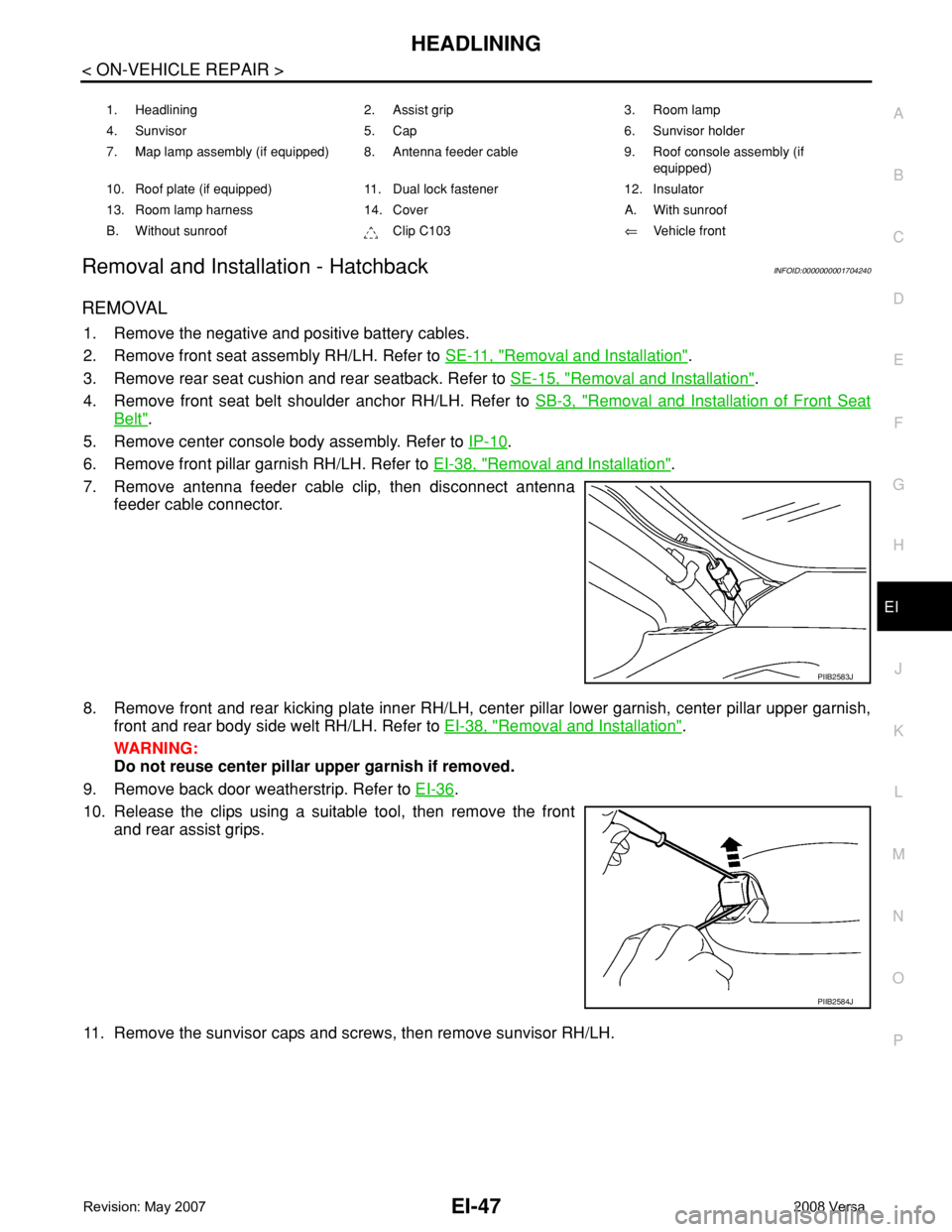
7. Remove antenna feeder cable clip, then disconnect antenna
feeder cable connector.
8. Remove front and rear kicking plate inner RH/LH, center pillar lower garnish, center pillar upper garnish,
front and rear body side welt RH/LH. Refer to EI-38, "
Removal and Installation".
WARNING:
Do not reuse center pillar upper garnish if removed.
9. Remove back door weatherstrip. Refer to EI-36
.
10. Release the clips using a suitable tool, then remove the front
and rear assist grips.
11. Remove the sunvisor caps and screws, then remove sunvisor RH/LH.
1. Headlining 2. Assist grip 3. Room lamp
4. Sunvisor 5. Cap 6. Sunvisor holder
7. Map lamp assembly (if equipped) 8. Antenna feeder cable 9. Roof console assembly (if
equipped)
10. Roof plate (if equipped) 11. Dual lock fastener 12. Insulator
13. Room lamp harness 14. Cover A. With sunroof
B. Without sunroof Clip C103⇐Vehicle front
PIIB2583J
PIIB2584J
Page 1671 of 2771
EI-48
< ON-VEHICLE REPAIR >
HEADLINING
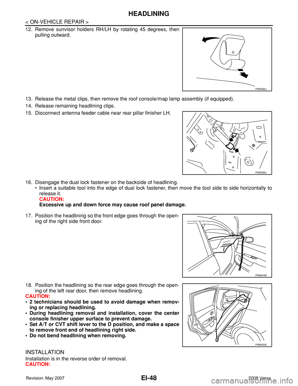
12. Remove sunvisor holders RH/LH by rotating 45 degrees, then
pulling outward.
13. Release the metal clips, then remove the roof console/map lamp assembly (if equipped).
14. Release remaining headlining clips.
15. Disconnect antenna feeder cable near rear pillar finisher LH.
16. Disengage the dual lock fastener on the backside of headlining.
• Insert a suitable tool into the edge of dual lock fastener, then move the tool side to side horizontally to
release it.
CAUTION:
Excessive up and down force may cause roof panel damage.
17. Position the headlining so the front edge goes through the open-
ing of the right side front door.
18. Position the headlining so the rear edge goes through the open-
ing of the left rear door, then remove headlining.
CAUTION:
• 2 technicians should be used to avoid damage when remov-
ing or replacing headlining.
• During headlining removal and installation, cover the center
console finisher upper surface to prevent damage.
• Set A/T or CVT shift lever to the D position, and make a space
to remove front end of headlining right side.
• Do not bend headlining when removing.
INSTALLATION
Installation is in the reverse order of removal.
CAUTION:
PIIB3982J
PIIB2586J
PIIB6049E
PIIB6050E