door finisher NISSAN TIIDA 2008 Service Repair Manual
[x] Cancel search | Manufacturer: NISSAN, Model Year: 2008, Model line: TIIDA, Model: NISSAN TIIDA 2008Pages: 2771, PDF Size: 60.61 MB
Page 363 of 2771
AV-4
< SERVICE INFORMATION >
AUDIO
AUDIO
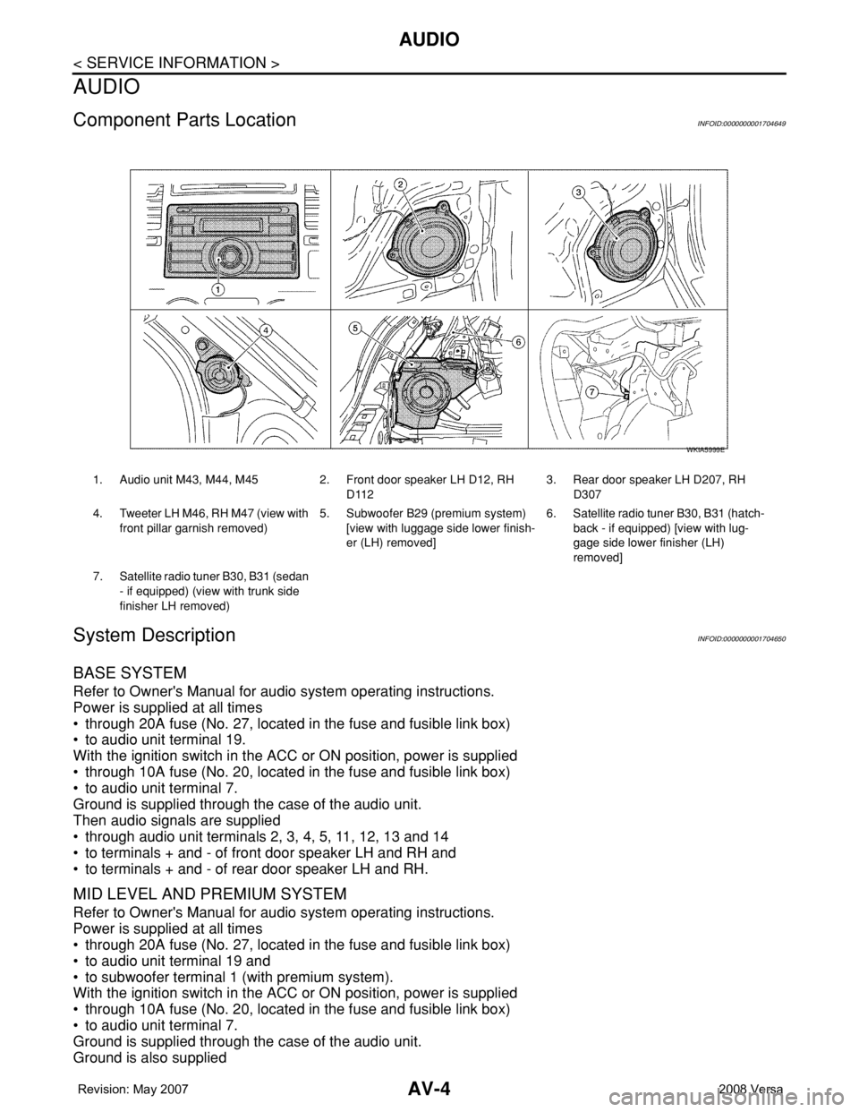
Component Parts LocationINFOID:0000000001704649
System DescriptionINFOID:0000000001704650
BASE SYSTEM
Refer to Owner's Manual for audio system operating instructions.
Power is supplied at all times
• through 20A fuse (No. 27, located in the fuse and fusible link box)
• to audio unit terminal 19.
With the ignition switch in the ACC or ON position, power is supplied
• through 10A fuse (No. 20, located in the fuse and fusible link box)
• to audio unit terminal 7.
Ground is supplied through the case of the audio unit.
Then audio signals are supplied
• through audio unit terminals 2, 3, 4, 5, 11, 12, 13 and 14
• to terminals + and - of front door speaker LH and RH and
• to terminals + and - of rear door speaker LH and RH.
MID LEVEL AND PREMIUM SYSTEM
Refer to Owner's Manual for audio system operating instructions.
Power is supplied at all times
• through 20A fuse (No. 27, located in the fuse and fusible link box)
• to audio unit terminal 19 and
• to subwoofer terminal 1 (with premium system).
With the ignition switch in the ACC or ON position, power is supplied
• through 10A fuse (No. 20, located in the fuse and fusible link box)
• to audio unit terminal 7.
Ground is supplied through the case of the audio unit.
Ground is also supplied
1. Audio unit M43, M44, M45 2. Front door speaker LH D12, RH
D1123. Rear door speaker LH D207, RH
D307
4. Tweeter LH M46, RH M47 (view with
front pillar garnish removed) 5. Subwoofer B29 (premium system)
[view with luggage side lower finish-
er (LH) removed]6. Satellite radio tuner B30, B31 (hatch-
back - if equipped) [view with lug-
gage side lower finisher (LH)
removed]
7. Satellite radio tuner B30, B31 (sedan
- if equipped) (view with trunk side
finisher LH removed)
WKIA5999E
Page 395 of 2771
AV-36
< SERVICE INFORMATION >
AUDIO
OK or NG
OK >> Replace subwoofer. Refer to AV-36, "Removal and Installation" .
NG >> Replace audio unit. Refer to AV-36, "
Removal and Installation" .
Removal and InstallationINFOID:0000000001704674
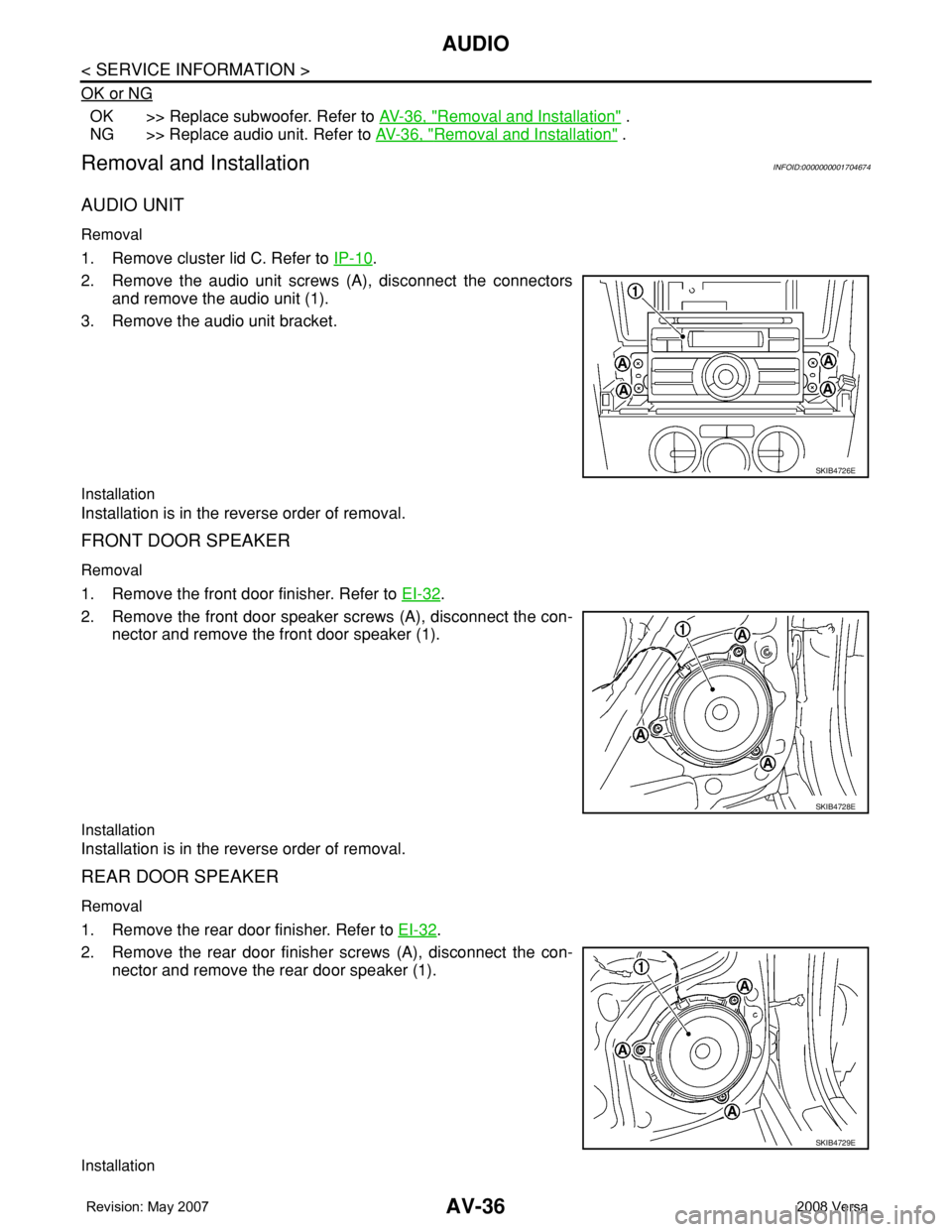
AUDIO UNIT
Removal
1. Remove cluster lid C. Refer to IP-10.
2. Remove the audio unit screws (A), disconnect the connectors
and remove the audio unit (1).
3. Remove the audio unit bracket.
Installation
Installation is in the reverse order of removal.
FRONT DOOR SPEAKER
Removal
1. Remove the front door finisher. Refer to EI-32.
2. Remove the front door speaker screws (A), disconnect the con-
nector and remove the front door speaker (1).
Installation
Installation is in the reverse order of removal.
REAR DOOR SPEAKER
Removal
1. Remove the rear door finisher. Refer to EI-32.
2. Remove the rear door finisher screws (A), disconnect the con-
nector and remove the rear door speaker (1).
Installation
SKIB4726E
SKIB4728E
SKIB4729E
Page 443 of 2771
SQUEAK AND RATTLE TROUBLE DIAGNOSES
BL-9
< SERVICE INFORMATION >
C
D
E
F
G
H
J
K
L
MA
B
BL
N
O
P
SILICONE GREASE
Used instead of UHMW tape that will be visible or not fit.
Note: Will only last a few months.
SILICONE SPRAY
Use when grease cannot be applied.
DUCT TAPE
Use to eliminate movement.
CONFIRM THE REPAIR
Confirm that the cause of a noise is repaired by test driving the vehicle. Operate the vehicle under the same
conditions as when the noise originally occurred. Refer to the notes on the Diagnostic Worksheet.
Generic Squeak and Rattle TroubleshootingINFOID:0000000001703945
Refer to Table of Contents for specific component removal and installation information.
INSTRUMENT PANEL
Most incidents are caused by contact and movement between:
1. The cluster lid A and instrument panel
2. Acrylic lens and combination meter housing
3. Instrument panel to front pillar garnish
4. Instrument panel to windshield
5. Instrument panel mounting pins
6. Wiring harnesses behind the combination meter
7. A/C defroster duct and duct joint
These incidents can usually be located by tapping or moving the components to duplicate the noise or by
pressing on the components while driving to stop the noise. Most of these incidents can be repaired by apply-
ing felt cloth tape or silicone spray (in hard to reach areas). Urethane pads can be used to insulate wiring har-
ness.
CAUTION:
Do not use silicone spray to isolate a squeak or rattle. If you saturate the area with silicone, you will
not be able to recheck the repair.
CENTER CONSOLE
Components to pay attention to include:
1. Shifter assembly cover to finisher
2. A/C control unit and cluster lid C
3. Wiring harnesses behind audio and A/C control unit
The instrument panel repair and isolation procedures also apply to the center console.
DOORS
Pay attention to the:
1. Finisher and inner panel making a slapping noise
2. Inside handle escutcheon to door finisher
3. Wiring harnesses tapping
4. Door striker out of alignment causing a popping noise on starts and stops
Tapping or moving the components or pressing on them while driving to duplicate the conditions can isolate
many of these incidents. You can usually insulate the areas with felt cloth tape or insulator foam blocks from
the NISSAN Squeak and Rattle Kit (J-43980) to repair the noise.
TRUNK
Trunk noises are often caused by a loose jack or loose items put into the trunk by the owner.
In addition look for:
1. Trunk lid bumpers out of adjustment
2. Trunk lid striker out of adjustment
3. The trunk lid torsion bars knocking together
4. A loose license plate or bracket
Page 509 of 2771
INTELLIGENT KEY SYSTEM
BL-75
< SERVICE INFORMATION >
C
D
E
F
G
H
J
K
L
MA
B
BL
N
O
P
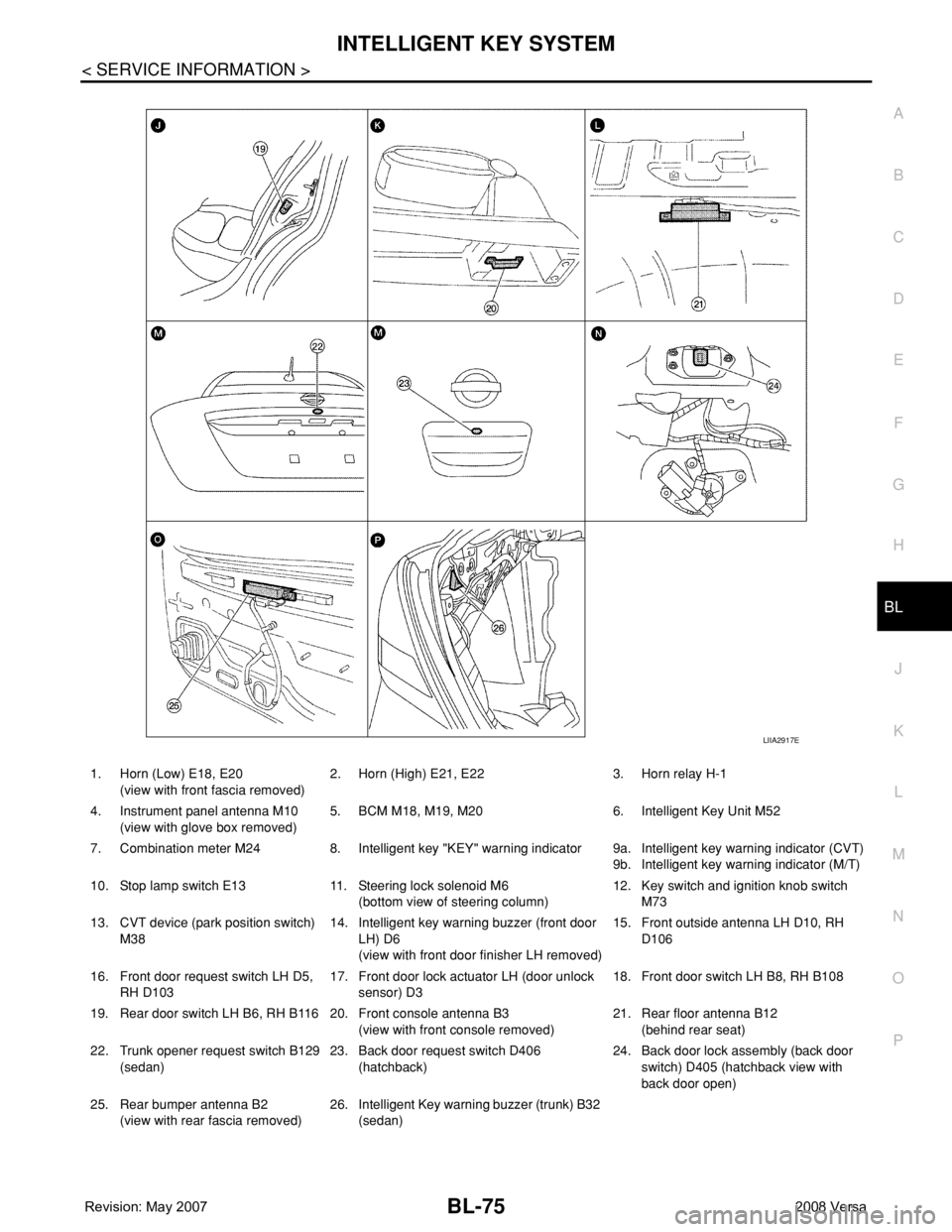
1. Horn (Low) E18, E20
(view with front fascia removed)2. Horn (High) E21, E22 3. Horn relay H-1
4. Instrument panel antenna M10
(view with glove box removed)5. BCM M18, M19, M20 6. Intelligent Key Unit M52
7. Combination meter M24 8. Intelligent key "KEY" warning indicator 9a.
9b.Intelligent key warning indicator (CVT)
Intelligent key warning indicator (M/T)
10. Stop lamp switch E13 11. Steering lock solenoid M6
(bottom view of steering column)12. Key switch and ignition knob switch
M73
13. CVT device (park position switch)
M3814. Intelligent key warning buzzer (front door
LH) D6
(view with front door finisher LH removed)15. Front outside antenna LH D10, RH
D106
16. Front door request switch LH D5,
RH D10317. Front door lock actuator LH (door unlock
sensor) D318. Front door switch LH B8, RH B108
19. Rear door switch LH B6, RH B116 20. Front console antenna B3
(view with front console removed)21. Rear floor antenna B12
(behind rear seat)
22. Trunk opener request switch B129
(sedan)23. Back door request switch D406
(hatchback)24. Back door lock assembly (back door
switch) D405 (hatchback view with
back door open)
25. Rear bumper antenna B2
(view with rear fascia removed)26. Intelligent Key warning buzzer (trunk) B32
(sedan)
LIIA2917E
Page 581 of 2771
DOOR
BL-147
< SERVICE INFORMATION >
C
D
E
F
G
H
J
K
L
MA
B
BL
N
O
P
1.
Removal and InstallationINFOID:0000000001704046
FRONT DOOR
CAUTION:
• When removing and installing the front door assembly, support the door with a jack and cloth to pro-
tect the door and body.
• When removing and installing front door assembly, be sure to carry out the fitting adjustment. Refer
to BL-144, "
Fitting Adjustment".
• After installing, apply touch-up paint onto the head of the hinge nuts.
• Check the hinge rotating part for lubrication. If necessary, apply “body grease”.
• Operate with two workers, because of its heavy weight.
• Check front door open/close operation after installation.
Removal
1. Remove dash side finisher. Refer to EI-38, "Removal and Installation".
2. Disconnect the front door harness connectors.
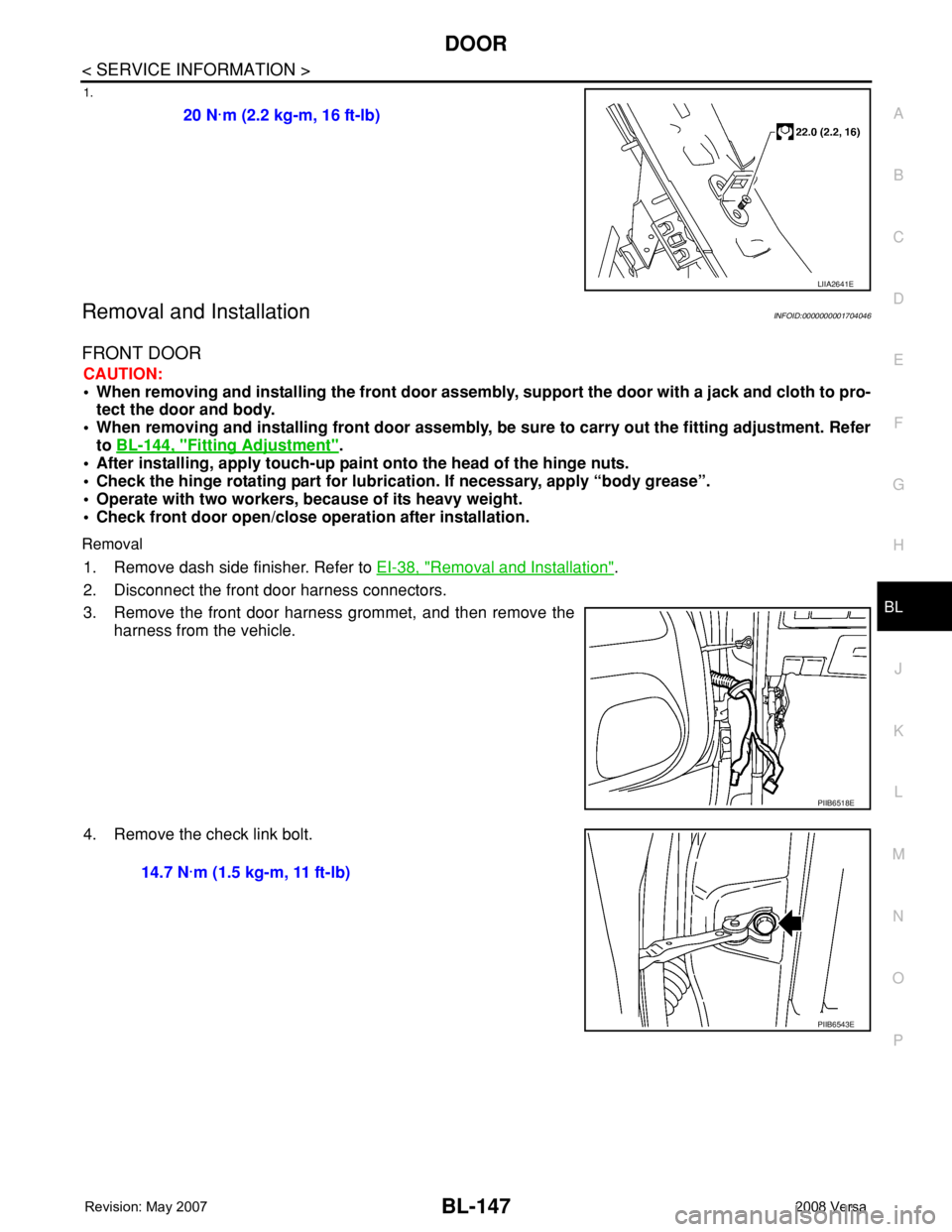
3. Remove the front door harness grommet, and then remove the
harness from the vehicle.
4. Remove the check link bolt.20 N·m (2.2 kg-m, 16 ft-lb)
LIIA2641E
PIIB6518E
14.7 N·m (1.5 kg-m, 11 ft-lb)
PIIB6543E
Page 584 of 2771
BL-150
< SERVICE INFORMATION >
FRONT DOOR LOCK
FRONT DOOR LOCK
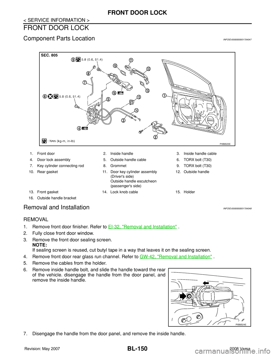
Component Parts LocationINFOID:0000000001704047
Removal and InstallationINFOID:0000000001704048
REMOVAL
1. Remove front door finisher. Refer to EI-32, "Removal and Installation" .
2. Fully close front door window.
3. Remove the front door sealing screen.
NOTE:
If sealing screen is reused, cut butyl tape in a way that leaves it on the sealing screen.
4. Remove front door rear glass run channel. Refer to GW-42, "
Removal and Installation" .
5. Remove the cables from the holder.
6. Remove inside handle bolt, and slide the handle toward the rear
of the vehicle. disengage the handle from the door panel, and
remove the inside handle.
7. Disengage the handle from the door panel, and remove the inside handle.
1. Front door 2. Inside handle 3. Inside handle cable
4. Door lock assembly 5. Outside handle cable 6. TORX bolt (T30)
7. Key cylinder connecting rod 8. Grommet 9. TORX bolt (T30)
10. Rear gasket 11. Door key cylinder assembly
(Driver's side)
Outside handle escutcheon
(passenger's side)12. Outside handle
13. Front gasket 14. Lock knob cable 15. Holder
16. Outside handle bracket
PIIB6523E
PIIB6524E
Page 602 of 2771
BL-168
< SERVICE INFORMATION >
BACK DOOR LOCK
OK or NG
OK >> Check the condition of harness and connector.
NG >> Replace BCM. Refer to BCS-18, "
Removal and Installation of BCM".
Removal and InstallationINFOID:0000000001704064
BACK DOOR LOCK
Removal
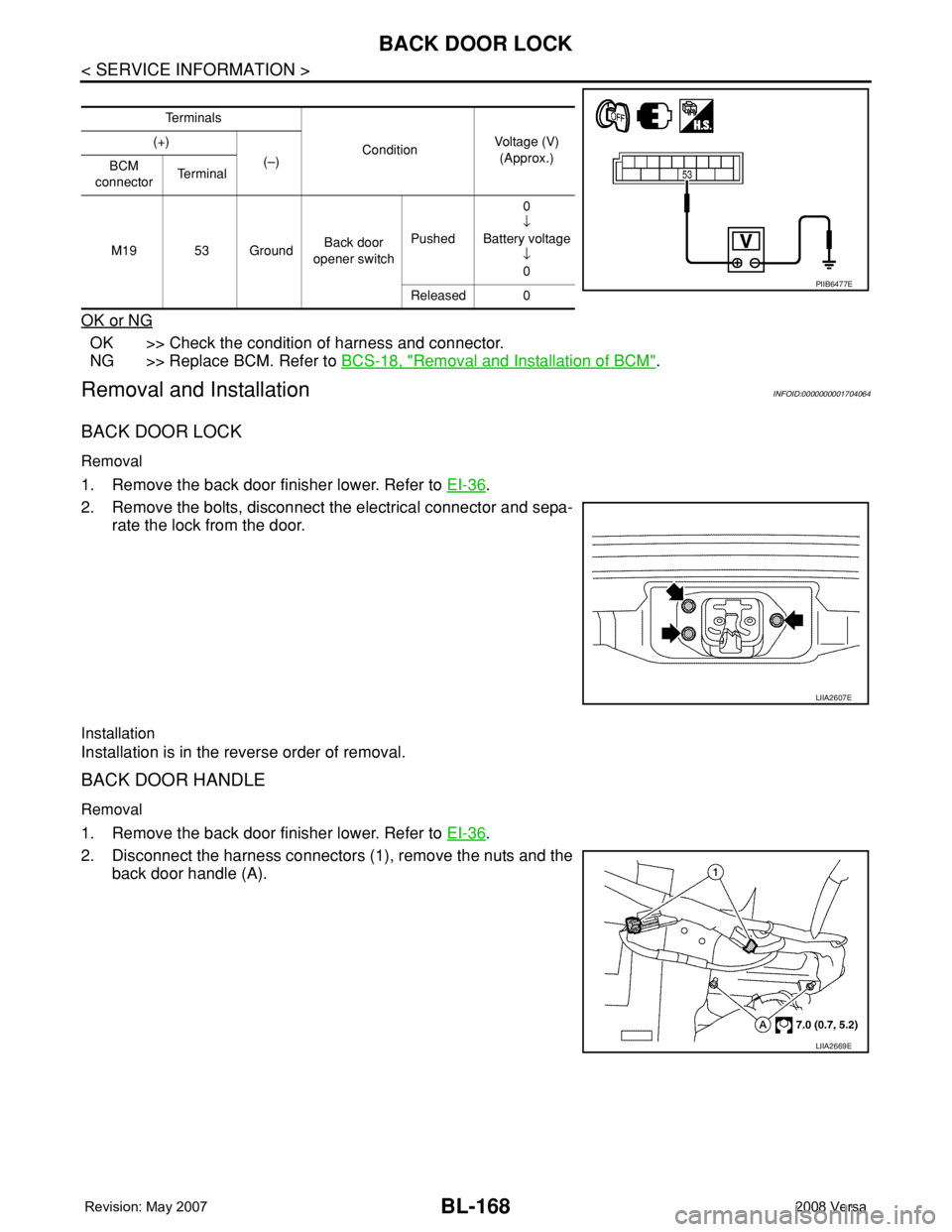
1. Remove the back door finisher lower. Refer to EI-36.
2. Remove the bolts, disconnect the electrical connector and sepa-
rate the lock from the door.
Installation
Installation is in the reverse order of removal.
BACK DOOR HANDLE
Removal
1. Remove the back door finisher lower. Refer to EI-36.
2. Disconnect the harness connectors (1), remove the nuts and the
back door handle (A).
Te r m i n a l s
ConditionVoltage (V)
(Approx.) (+)
(–)
BCM
connectorTe r m i n a l
M19 53 GroundBack door
opener switchPushed0
↓
Battery voltage
↓
0
Released 0
PIIB6477E
LIIA2607E
LIIA2669E
Page 1624 of 2771

EI-1
BODY
C
D
E
F
G
H
J
K
L
M
SECTION EI
A
B
EI
N
O
P
CONTENTS
EXTERIOR & INTERIOR
PRECAUTION ...............................................3
PRECAUTIONS ...................................................3
Precaution for Supplemental Restraint System
(SRS) "AIR BAG" and "SEAT BELT PRE-TEN-
SIONER" ...................................................................
3
Precaution .................................................................3
PREPARATION ............................................4
PREPARATION ...................................................4
Special Service Tool .................................................4
Commercial Service Tool ..........................................4
SYMPTOM DIAGNOSIS ...............................5
SQUEAK AND RATTLE TROUBLE DIAGNO-
SIS .......................................................................
5
Work Flow .................................................................5
Generic Squeak and Rattle Troubleshooting ............7
Diagnostic Worksheet ...............................................9
CLIP AND FASTENER .......................................11
Description ..............................................................11
ON-VEHICLE REPAIR .................................14
FRONT BUMPER ...............................................14
Removal and Installation .........................................14
REAR BUMPER .................................................16
Component ..............................................................16
Removal and Installation - Hatchback .....................17
Removal and Installation - Sedan ...........................18
FRONT GRILLE .................................................20
Removal and Installation .........................................20
COWL TOP .........................................................21
Removal and Installation .........................................21
FENDER PROTECTOR ......................................23
Component ..............................................................23
Removal and Installation .........................................23
ROOF SIDE MOLDING .....................................24
Component ..............................................................24
Removal and Installation .........................................24
DOOR OUTSIDE MOLDING .............................26
Component ..............................................................26
Removal and Installation .........................................27
CENTER MUD GUARD .....................................29
Removal and Installation .........................................29
TRUNK LID FINISHER ......................................30
Removal and Installation .........................................30
REAR AIR SPOILER .........................................31
Removal and Installation .........................................31
DOOR FINISHER ..............................................32
Removal and Installation .........................................32
BACK DOOR TRIM ...........................................36
Removal and Installation .........................................36
BODY SIDE TRIM .............................................37
Component ..............................................................37
Removal and Installation .........................................38
REAR PARCEL SHELF FINISHER ..................42
Removal and Installation .........................................42
FLOOR TRIM ....................................................43
Removal and Installation .........................................43
HEADLINING ....................................................45
Component ..............................................................45
Removal and Installation - Hatchback .....................47
Removal and Installation - Sedan ............................49
LUGGAGE FLOOR TRIM .................................51
Removal and Installation .........................................51
Page 1630 of 2771
SQUEAK AND RATTLE TROUBLE DIAGNOSIS
EI-7
< SYMPTOM DIAGNOSIS >
C
D
E
F
G
H
J
K
L
MA
B
EI
N
O
P
The following materials, not found in the kit, can also be used to repair squeaks and rattles.
UHMW (TEFLON) TAPE
Insulates where slight movement is present. Ideal for instrument panel applications.
SILICONE GREASE
Used in place of UHMW tape that will be visible or not fit.
Note: Will only last a few months.
SILICONE SPRAY
Use when grease cannot be applied.
DUCT TAPE
Use to eliminate movement.
CONFIRM THE REPAIR
Confirm that the cause of a noise is repaired by test driving the vehicle. Operate the vehicle under the same
conditions as when the noise originally occurred. Refer to the notes on the Diagnostic Worksheet.
Generic Squeak and Rattle TroubleshootingINFOID:0000000001704215
Refer to Table of Contents for specific component removal and installation information.
INSTRUMENT PANEL
Most incidents are caused by contact and movement between:
1. The cluster lid A and instrument panel
2. Acrylic lens and combination meter housing
3. Instrument panel to front pillar garnish
4. Instrument panel to windshield
5. Instrument panel pins
6. Wiring harnesses behind the combination meter
7. A/C defroster duct and duct joint
These incidents can usually be located by tapping or moving the components to duplicate the noise or by
pressing on the components while driving to stop the noise. Most of these incidents can be repaired by apply-
ing felt cloth tape or silicone spray (in hard to reach areas). Urethane pads can be used to insulate wiring har-
ness.
CAUTION:
Do not use silicone spray to isolate a squeak or rattle. If you saturate the area with silicone, you will
not be able to recheck the repair.
CENTER CONSOLE
Components to pay attention to include:
1. Shifter assembly cover to finisher
2. A/C control unit and cluster lid C
3. Wiring harnesses behind audio and A/C control unit
The instrument panel repair and isolation procedures also apply to the center console.
DOORS
Pay attention to the:
1. Finisher and inner panel making a slapping noise
2. Inside handle escutcheon to door finisher
3. Wiring harnesses tapping
4. Door striker out of alignment causing a popping noise on starts and stops
Tapping or moving the components or pressing on them while driving to duplicate the conditions can isolate
many of these incidents. You can usually insulate the areas with felt cloth tape or insulator foam blocks from
the NISSAN Squeak and Rattle Kit (J-43980) to repair the noise.
TRUNK
Trunk noises are often caused by a loose jack or loose items put into the trunk by the owner.
In addition look for:
1. Trunk lid bumpers out of adjustment
2. Trunk lid striker out of adjustment
Page 1654 of 2771
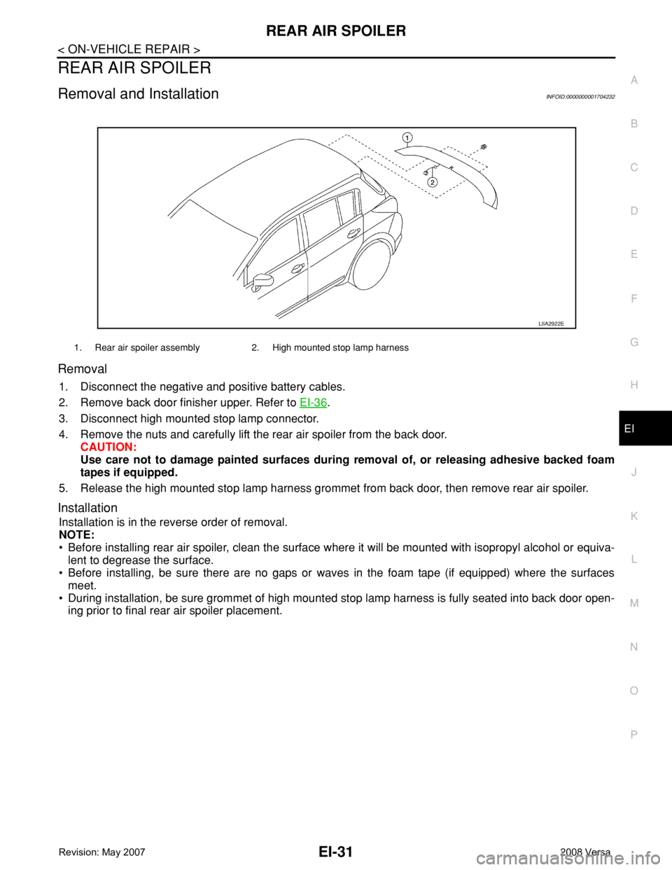
REAR AIR SPOILER
EI-31
< ON-VEHICLE REPAIR >
C
D
E
F
G
H
J
K
L
MA
B
EI
N
O
P
REAR AIR SPOILER
Removal and InstallationINFOID:0000000001704232
Removal
1. Disconnect the negative and positive battery cables.
2. Remove back door finisher upper. Refer to EI-36
.
3. Disconnect high mounted stop lamp connector.
4. Remove the nuts and carefully lift the rear air spoiler from the back door.
CAUTION:
Use care not to damage painted surfaces during removal of, or releasing adhesive backed foam
tapes if equipped.
5. Release the high mounted stop lamp harness grommet from back door, then remove rear air spoiler.
Installation
Installation is in the reverse order of removal.
NOTE:
• Before installing rear air spoiler, clean the surface where it will be mounted with isopropyl alcohol or equiva-
lent to degrease the surface.
• Before installing, be sure there are no gaps or waves in the foam tape (if equipped) where the surfaces
meet.
• During installation, be sure grommet of high mounted stop lamp harness is fully seated into back door open-
ing prior to final rear air spoiler placement.
1. Rear air spoiler assembly 2. High mounted stop lamp harness
LIIA2922E