garage jack NISSAN TIIDA 2008 Service Repair Manual
[x] Cancel search | Manufacturer: NISSAN, Model Year: 2008, Model line: TIIDA, Model: NISSAN TIIDA 2008Pages: 2771, PDF Size: 60.61 MB
Page 1750 of 2771

ENGINE ASSEMBLY
EM-73
< SERVICE INFORMATION >
C
D
E
F
G
H
I
J
K
L
MA
EM
N
P O
• Use either 2-pole lift type or separate type lift as best you can. If board-on type is used for unavoid-
able reasons, support at the rear axle jacking point with a transmission jack or similar tool before
starting work, in preparation for the backward shift of center of gravity.
• For supporting points for lifting and jacking point at rear axle, refer to GI-38, "
Garage Jack and
Safety Stand and 2-Pole Lift".
REMOVAL
Remove the engine and the transaxle assembly from the vehicle downward. Separate the engine and the tran-
saxle.
1. Remove engine undercover
2. Drain engine coolant from radiator. Refer to CO-8, "
Changing Engine Coolant".
CAUTION:
• Perform this step when the engine is cold.
• Do not spill engine coolant on drive belt.
3. Remove front fender protector (RH and LH); Refer to EI-23
.
4. Remove exhaust front tube; Refer to EX-4
.
5. Remove drive shafts (LH and RH) from steering knuckle. Refer to FAX-8
.
6. Remove transaxle joint bolts which pierce at oil pan (upper) lower rear side. Refer to AT-226
(A/T models),
CVT-178
(CVT) or MT-16 (M/T models).
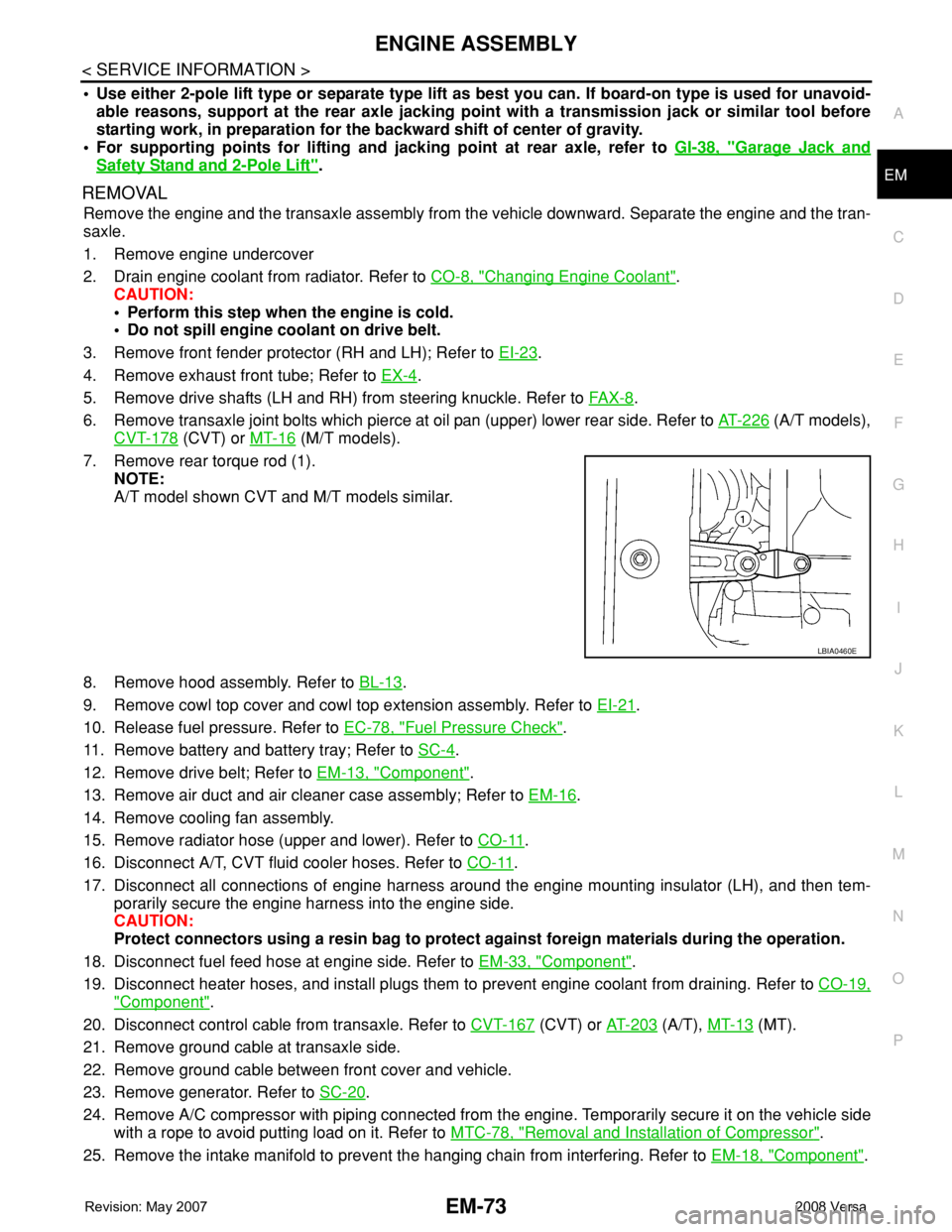
7. Remove rear torque rod (1).
NOTE:
A/T model shown CVT and M/T models similar.
8. Remove hood assembly. Refer to BL-13
.
9. Remove cowl top cover and cowl top extension assembly. Refer to EI-21
.
10. Release fuel pressure. Refer to EC-78, "
Fuel Pressure Check".
11. Remove battery and battery tray; Refer to SC-4
.
12. Remove drive belt; Refer to EM-13, "
Component".
13. Remove air duct and air cleaner case assembly; Refer to EM-16
.
14. Remove cooling fan assembly.
15. Remove radiator hose (upper and lower). Refer to CO-11
.
16. Disconnect A/T, CVT fluid cooler hoses. Refer to CO-11
.
17. Disconnect all connections of engine harness around the engine mounting insulator (LH), and then tem-
porarily secure the engine harness into the engine side.
CAUTION:
Protect connectors using a resin bag to protect against foreign materials during the operation.
18. Disconnect fuel feed hose at engine side. Refer to EM-33, "
Component".
19. Disconnect heater hoses, and install plugs them to prevent engine coolant from draining. Refer to CO-19,
"Component".
20. Disconnect control cable from transaxle. Refer to CVT-167
(CVT) or AT-203 (A/T), MT-13 (MT).
21. Remove ground cable at transaxle side.
22. Remove ground cable between front cover and vehicle.
23. Remove generator. Refer to SC-20
.
24. Remove A/C compressor with piping connected from the engine. Temporarily secure it on the vehicle side
with a rope to avoid putting load on it. Refer to MTC-78, "
Removal and Installation of Compressor".
25. Remove the intake manifold to prevent the hanging chain from interfering. Refer to EM-18, "
Component".
LBIA0460E
Page 1852 of 2771

GI-1
GENERAL INFORMATION
C
D
E
F
G
H
I
J
K
L
MB
GI
SECTION GI
N
O
P
CONTENTS
GENERAL INFORMATION
SERVICE INFORMATION ............................2
PRECAUTIONS ...................................................2
Description ................................................................2
Precaution for Supplemental Restraint System
(SRS) "AIR BAG" and "SEAT BELT PRE-TEN-
SIONER" ...................................................................
2
Precaution Necessary for Steering Wheel Rota-
tion After Battery Disconnect .....................................
2
General Precaution ...................................................3
Precaution for Three Way Catalyst ...........................4
Precaution for Fuel (Unleaded Regular Gasoline
Recommended) .........................................................
4
Precaution for Multiport Fuel Injection System or
Engine Control System .............................................
5
Precaution for Hoses .................................................5
Precaution for Engine Oils ........................................6
Precaution for Air Conditioning .................................6
HOW TO USE THIS MANUAL ............................7
Description ................................................................7
Terms ........................................................................7
Units ..........................................................................7
Contents ....................................................................7
Relation between Illustrations and Descriptions .......8
Component ................................................................8
How to Follow Trouble Diagnosis ..............................9
How to Read Wiring Diagram ..................................13
Abbreviations ..........................................................20
SERVICE INFORMATION FOR ELECTRICAL
INCIDENT ...........................................................
22
How to Check Terminal ...........................................22
How to Perform Efficient Diagnosis for an Electri-
cal Incident ..............................................................
25
Control Units and Electrical Parts ............................32
CONSULT-III CHECKING SYSTEM .................35
Description ...............................................................35
Function and System Application ............................35
CONSULT-III Data Link Connector (DLC) Circuit ....36
LIFTING POINT .................................................38
Special Service Tool ................................................38
Garage Jack and Safety Stand and 2-Pole Lift .......38
Board-On Lift ...........................................................39
TOW TRUCK TOWING .....................................40
Tow Truck Towing ...................................................40
Vehicle Recovery (Freeing a Stuck Vehicle) ...........40
TIGHTENING TORQUE OF STANDARD
BOLTS ...............................................................
41
Tightening Torque Table .........................................41
RECOMMENDED CHEMICAL PRODUCTS
AND SEALANTS ...............................................
42
Recommended Chemical Product and Sealant .......42
IDENTIFICATION INFORMATION ....................43
Model Variation ........................................................43
Dimensions ..............................................................46
Wheels & Tires ........................................................46
TERMINOLOGY ................................................47
SAE J1930 Terminology List ...................................47
Page 1889 of 2771

GI-38
< SERVICE INFORMATION >
LIFTING POINT
LIFTING POINT
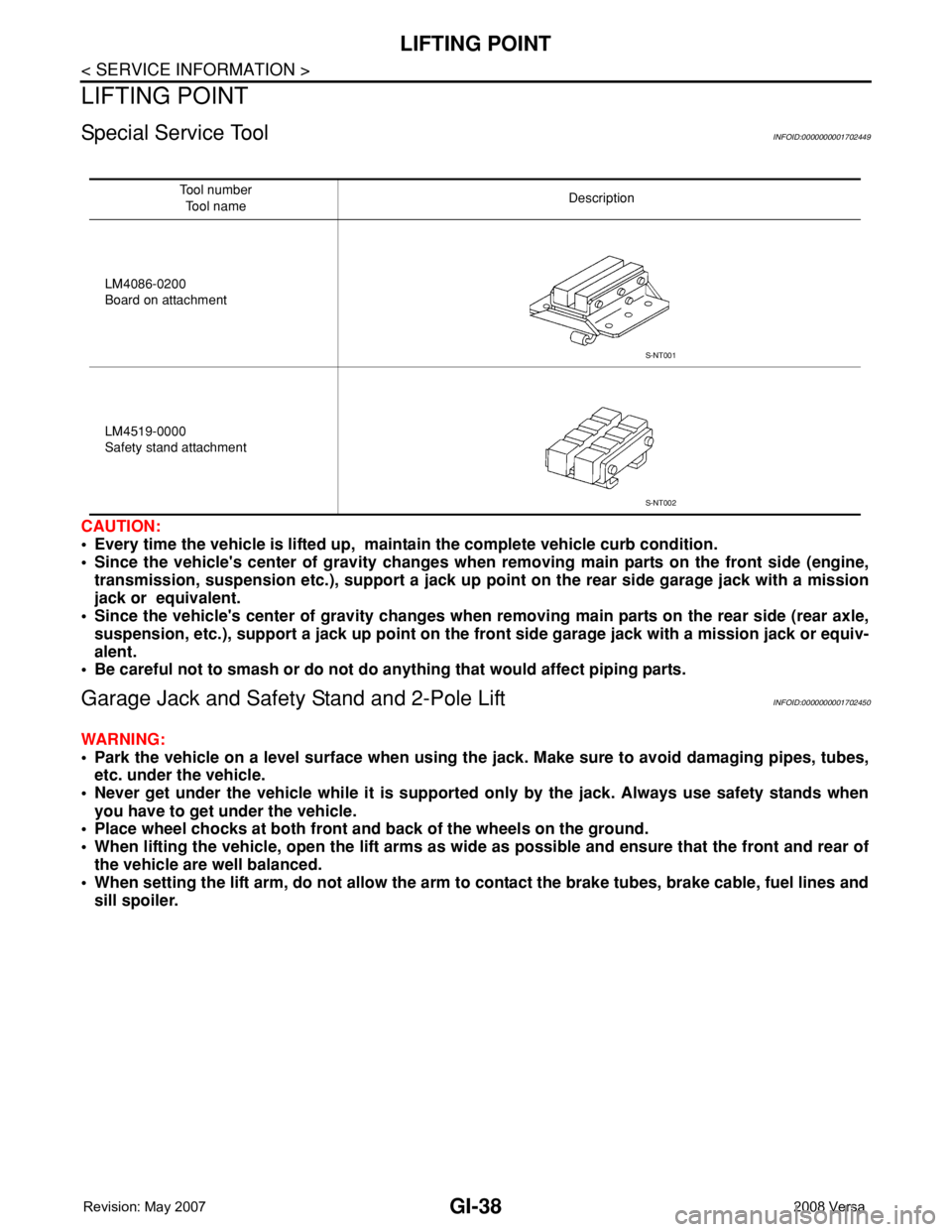
Special Service ToolINFOID:0000000001702449
CAUTION:
• Every time the vehicle is lifted up, maintain the complete vehicle curb condition.
• Since the vehicle's center of gravity changes when removing main parts on the front side (engine,
transmission, suspension etc.), support a jack up point on the rear side garage jack with a mission
jack or equivalent.
• Since the vehicle's center of gravity changes when removing main parts on the rear side (rear axle,
suspension, etc.), support a jack up point on the front side garage jack with a mission jack or equiv-
alent.
• Be careful not to smash or do not do anything that would affect piping parts.
Garage Jack and Safety Stand and 2-Pole LiftINFOID:0000000001702450
WARNING:
• Park the vehicle on a level surface when using the jack. Make sure to avoid damaging pipes, tubes,
etc. under the vehicle.
• Never get under the vehicle while it is supported only by the jack. Always use safety stands when
you have to get under the vehicle.
• Place wheel chocks at both front and back of the wheels on the ground.
• When lifting the vehicle, open the lift arms as wide as possible and ensure that the front and rear of
the vehicle are well balanced.
• When setting the lift arm, do not allow the arm to contact the brake tubes, brake cable, fuel lines and
sill spoiler.
Tool number
Tool nameDescription
LM4086-0200
Board on attachment
LM4519-0000
Safety stand attachment
S-NT001
S-NT002
Page 1890 of 2771

LIFTING POINT
GI-39
< SERVICE INFORMATION >
C
D
E
F
G
H
I
J
K
L
MB
GI
N
O
P
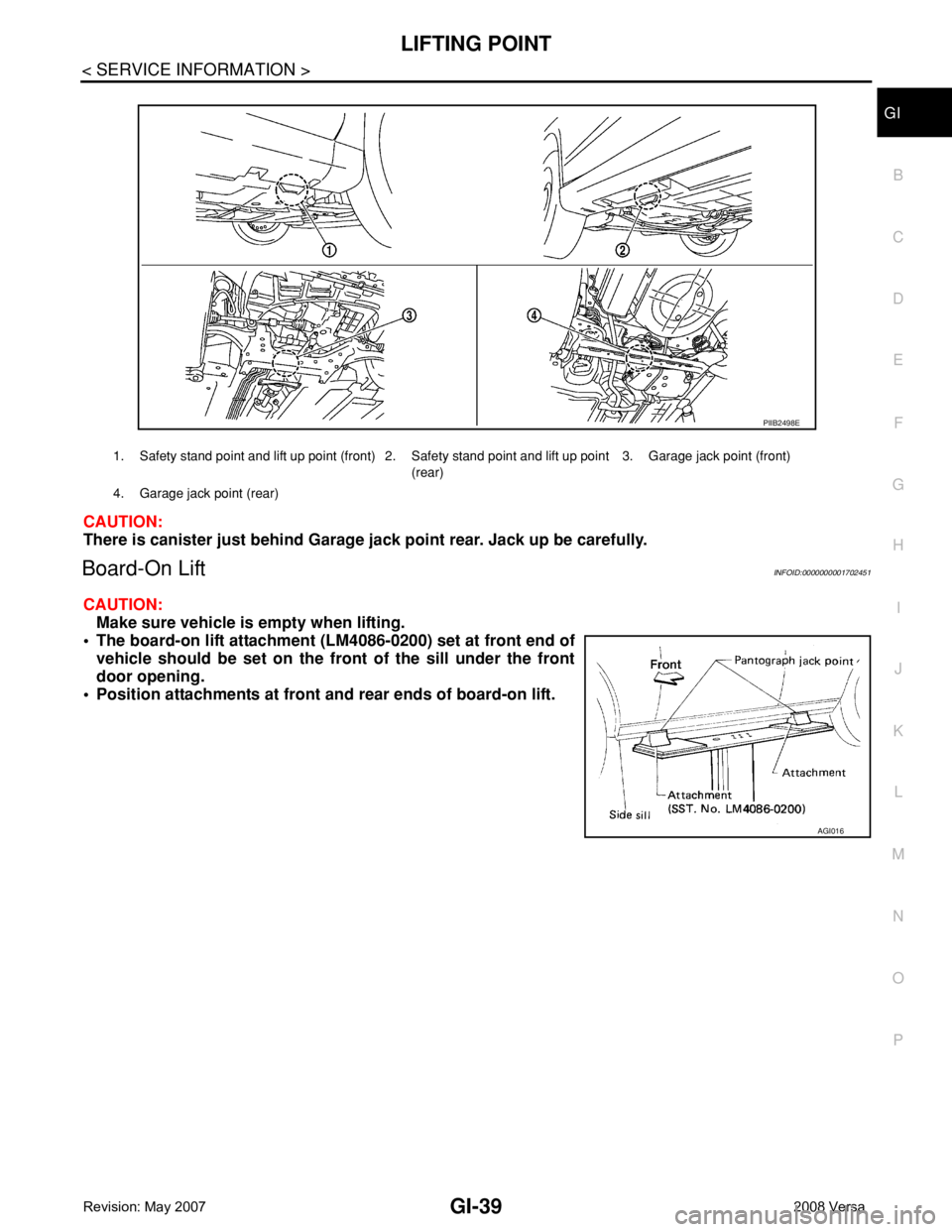
CAUTION:
There is canister just behind Garage jack point rear. Jack up be carefully.
Board-On LiftINFOID:0000000001702451
CAUTION:
Make sure vehicle is empty when lifting.
• The board-on lift attachment (LM4086-0200) set at front end of
vehicle should be set on the front of the sill under the front
door opening.
• Position attachments at front and rear ends of board-on lift.
1. Safety stand point and lift up point (front) 2. Safety stand point and lift up point
(rear)3. Garage jack point (front)
4. Garage jack point (rear)
PIIB2498E
AGI016