interior NISSAN TIIDA 2008 Service Repair Manual
[x] Cancel search | Manufacturer: NISSAN, Model Year: 2008, Model line: TIIDA, Model: NISSAN TIIDA 2008Pages: 2771, PDF Size: 60.61 MB
Page 1 of 2771
-1
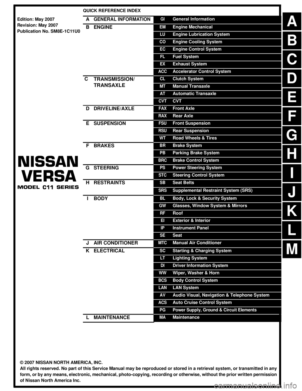
QUICK REFERENCE INDEX
AGENERAL INFORMATIONGIGeneral Information
BENGINEEMEngine Mechanical
LUEngine Lubrication System
COEngine Cooling System
ECEngine Control System
FLFuel System
EXExhaust System
ACCAccelerator Control System
CTRANSMISSION/
TRANSAXLECLClutch System
MTManual Transaxle
ATAutomatic Transaxle
CVTCVT
DDRIVELINE/AXLEFAXFront Axle
RAXRear Axle
ESUSPENSIONFSUFront Suspension
RSURear Suspension
WTRoad Wheels & Tires
FBRAKESBRBrake System
PBParking Brake System
BRCBrake Control System
GSTEERINGPSPower Steering System
STCSteering Control System
HRESTRAINTSSBSeat Belts
SRSSupplemental Restraint System (SRS)
IBODYBLBody, Lock & Security System
GWGlasses, Window System & Mirrors
RFRoof
EIExterior & Interior
IPInstrument Panel
SESeat
JAIR CONDITIONERMTCManual Air Conditioner
KELECTRICALSCStarting & Charging System
LTLighting System
DIDriver Information System
WWWiper, Washer & Horn
BCSBody Control System
LANLAN System
AVAudio Visual, Navigation & Telephone System
ACSAuto Cruise Control System
PGPower Supply, Ground & Circuit Elements
LMAINTENANCEMAMaintenance
Edition: May 2007
Revision: May 2007
Publication No. SM8E-1C11U0
B
D
© 2007 NISSAN NORTH AMERICA, INC.
All rights reserved. No part of this Service Manual may be reproduced or stored in a retrieval system, or transmitted in any
form, or by any means, electronic, mechanical, photo-copying, recording or otherwise, without the prior written permission
of Nissan North America Inc.
A
C
E
F
G
H
I
J
K
L
M
Page 423 of 2771

BCM (BODY CONTROL MODULE)
BCS-7
< SERVICE INFORMATION >
C
D
E
F
G
H
I
J
L
MA
B
BCS
N
O
P
CAN Communication System DescriptionINFOID:0000000001704585
Refer to LAN-6, "System Description".
Panic alarm• Key switch
•KeyfobIPDM E/R
Vehicle security system• All door switches
•Keyfob
• Door lock/unlock switch
• Trunk key cylinder switch (Se-
dan)
• Front door key cylinder switch
LH• IPDM/ER
• Security indicator lamp
Battery saver control• Ignition switch
• Combination switchIPDM E/R
Headlamp Combination switch IPDM E/R
Tail lamp Combination switch IPDM E/R
Front fog lamp Combination switch IPDM E/R
Turn signal lamp Combination switch• Turn signal lamp
• Combination meter
Hazard lamp Hazard switch• Turn signal lamp
• Combination meter
Room lamp timer• Key switch
•Keyfob
• Main power window and door
lock/unlock switch
• Front door switch LH
• All door switchInterior room lamp
Back door switch signal (Hatchback) Back door lock assembly Luggage room lamp
Back door lock signal (Hatchback) Back door lock assembly Back door opener
Trunk lamp switch signalTrunk lamp switch and trunk re-
lease solenoidLuggage room lamp
Trunk lid opener signalTrunk lamp switch and trunk re-
lease solenoidTrunk lid opener
Key warning chime• Key switch
• Front door switch LHCombination meter (warning buzzer)
Light warning chime• Combination switch
• Key switch
• Front door switch LHCombination meter (warning buzzer)
Seat belt warning chime• Seat belt buckle switch LH
• Ignition switchCombination meter (warning buzzer)
Front wiper and washer system• Combination switch
• Ignition switchIPDM E/R
Rear window defogger Rear window defogger switch IPDM E/R
Rear wiper and washer system• Combination switch
• Ignition switchRear wiper motor
A/C switch signal Front air control ECM
Blower fan switch signal Front air control ECM
A/C indicator signal Front air control A/C indicator
Low tire pressure warning system Remote keyless entry receiver Combination meterSystem Input Output
Page 430 of 2771
BCS-14
< SERVICE INFORMATION >
BCM (BODY CONTROL MODULE)
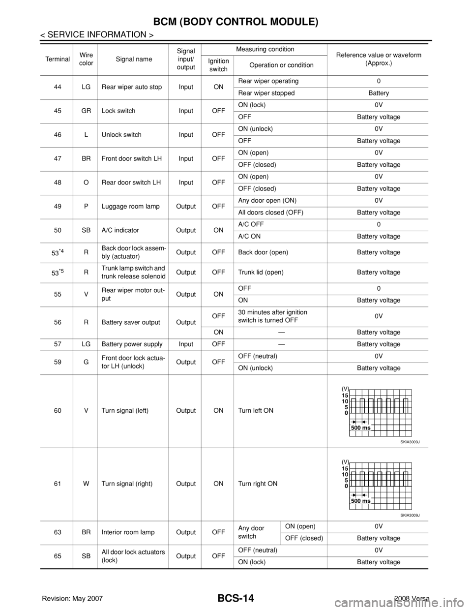
44 LG Rear wiper auto stop Input ONRear wiper operating 0
Rear wiper stopped Battery
45 GR Lock switch Input OFFON (lock) 0V
OFF Battery voltage
46 L Unlock switch Input OFFON (unlock) 0V
OFF Battery voltage
47 BR Front door switch LH Input OFFON (open) 0V
OFF (closed) Battery voltage
48 O Rear door switch LH Input OFFON (open) 0V
OFF (closed) Battery voltage
49 P Luggage room lamp Output OFFAny door open (ON) 0V
All doors closed (OFF) Battery voltage
50 SB A/C indicator Output ONA/C OFF 0
A/C ON Battery voltage
53
*4RBack door lock assem-
bly (actuator)Output OFF Back door (open) Battery voltage
53
*5RTrunk lamp switch and
trunk release solenoidOutput OFF Trunk lid (open) Battery voltage
55 VRear wiper motor out-
putOutput ONOFF 0
ON Battery voltage
56 R Battery saver output OutputOFF30 minutes after ignition
switch is turned OFF0V
ON — Battery voltage
57 LG Battery power supply Input OFF — Battery voltage
59 GFront door lock actua-
tor LH (unlock)Output OFFOFF (neutral) 0V
ON (unlock) Battery voltage
60 V Turn signal (left) Output ON Turn left ON
61 W Turn signal (right) Output ON Turn right ON
63 BR Interior room lamp Output OFFAny door
switchON (open) 0V
OFF (closed) Battery voltage
65 SBAll door lock actuators
(lock)Output OFFOFF (neutral) 0V
ON (lock) Battery voltage Te r m i n a lWire
colorSignal nameSignal
input/
outputMeasuring condition
Reference value or waveform
(Approx.) Ignition
switchOperation or condition
SKIA3009J
SKIA3009J
Page 433 of 2771

BCM (BODY CONTROL MODULE)
BCS-17
< SERVICE INFORMATION >
C
D
E
F
G
H
I
J
L
MA
B
BCS
N
O
P
WORK SUPPORT
Display Item List
CAN Communication Inspection Using CONSULT-III (Self-Diagnosis)INFOID:0000000001704591
1.SELF-DIAGNOSTIC RESULT CHECK
1. Connect CONSULT–III and select “BCM” on “SELECT SYSTEM” screen.
2. Select “BCM” on “SELECT TEST ITEM” screen, and select “SELF-DIAG RESULTS”.
3. Check display content in self-diagnostic results.
Contents displayed
No malfunction>>Inspection End
Malfunction in CAN communication system>>After printing the monitor items, go to “CAN System”. Refer to
LAN-15, "
Trouble Diagnosis Flow Chart".
ConfigurationINFOID:0000000001806223
DESCRIPTION
CONFIGURATION has three functions as follows:
• READ CONFIGURATION is the function to read (extract) vehicle configuration of current BCM.
Blower fan switch sig-
nal
Air conditioner switch
signalAIR CONDITION-
ER×
Intelligent KeyINTELLIGENT
KEY×
Combination switch COMB SW×
NVIS (NATS) IMMU××
Interior lamp battery
saverBATTERY SAV-
ER×××
Back door/Trunk TRUNK××
Theft alarm THEFT ALARM×××
Retained accessory
power controlRETAINED PWR×××
Oil pressure switch SIGNAL BUFFER××
Low tire pressure moni-
torAIR PRESSURE
MONITOR×× × ×
Panic alarm PANIC ALARM× System and itemCONSULT-III dis-
playDiagnostic test mode (Inspection by part)
WORK
SUPPORTSELF−
DIAG RE-
SULTSCAN DIAG
SUPPORT
MNTRDATA
MONITORECU
PA R T
NUMBERAC-
TIVE
TESTCON-
FIGU-
RATION
Item Description
RESET SETTING VALUE Return a value set with WORK SUPPORT of each system to a default value in factory shipment.
CONSULT-III display code Diagnosis item
U1000INITIAL DIAG
TRANSMIT DIAG
ECM
IPDM E/R
METER/M&A
I-KEY
Page 435 of 2771

BL-1
BODY
C
D
E
F
G
H
J
K
L
M
SECTION BL
A
B
BL
N
O
P
CONTENTS
BODY, LOCK & SECURITY SYSTEM
SERVICE INFORMATION ............................4
PRECAUTIONS ...................................................4
Precaution for Supplemental Restraint System
(SRS) "AIR BAG" and "SEAT BELT PRE-TEN-
SIONER" ...................................................................
4
Precaution Necessary for Steering Wheel Rota-
tion After Battery Disconnect .....................................
4
Precaution for Procedure without Cowl Top Cover ......5
Precaution for Work ..................................................5
PREPARATION ...................................................6
Special Service Tool .................................................6
Commercial Service Tool ..........................................6
SQUEAK AND RATTLE TROUBLE DIAG-
NOSES ................................................................
7
Work Flow .................................................................7
Generic Squeak and Rattle Troubleshooting ............9
Diagnostic Worksheet .............................................11
HOOD .................................................................13
Fitting Adjustment ...................................................13
Removal and Installation .........................................14
Removal and Installation of Hood Lock Control ......15
Hood Lock Control Inspection .................................17
RADIATOR CORE SUPPORT ...........................19
Removal and Installation .........................................19
FRONT FENDER ................................................21
Removal and Installation .........................................21
POWER DOOR LOCK SYSTEM ........................22
Component Parts and Harness Connector Loca-
tion ..........................................................................
22
System Description .................................................22
CAN Communication System Description ...............24
Schematic ...............................................................25
Wiring Diagram - D/LOCK - .....................................26
Schematic ...............................................................30
Wiring Diagram - D/LOCK - .....................................31
Terminal and Reference Value for BCM ..................35
Work Flow ................................................................35
CONSULT-III Function (BCM) .................................36
Trouble Diagnosis Symptom Chart ..........................37
BCM Power Supply and Ground Circuit ..................37
Door Switch Check (Hatchback) ..............................37
Door Switch Check (Sedan) ....................................40
Key Switch (Insert) Check .......................................41
Door Lock and Unlock Switch Check ......................42
Front Door Lock Assembly LH (Actuator) Check .....45
Door Lock Actuator Check (Front RH and Rear
LH/RH) .....................................................................
46
Front Door Key Cylinder Switch LH Check ..............47
Passenger Select Unlock Relay Circuit Inspection
(With Intelligent Key) ...............................................
48
REMOTE KEYLESS ENTRY SYSTEM .............51
Component Parts and Harness Connector Loca-
tion ...........................................................................
51
System Description ..................................................51
CAN Communication System Description ...............53
Schematic ................................................................54
Wiring Diagram - KEYLES - ....................................55
Terminal and Reference Value for BCM ..................57
How to Perform Trouble Diagnosis ..........................57
Preliminary Check ...................................................58
CONSULT-III Function (BCM) .................................58
Work Flow ................................................................59
Trouble Diagnosis Symptom Chart ..........................60
Keyfob Battery and Function Check ........................61
ACC Switch Check ..................................................62
Door Switch Check (Hatchback) ..............................62
Door Switch Check (Sedan) ....................................65
Key Switch (Insert) Check .......................................66
Hazard Function Check ...........................................67
Horn Function Check ...............................................67
Interior Lamp and Ignition Keyhole Illumination
Function Check ........................................................
68
Remote Keyless Entry Receiver Check ...................68
Keyfob Function (Lock) Check ................................71
Keyfob Function (Unlock) Check .............................71
Page 444 of 2771

BL-10
< SERVICE INFORMATION >
SQUEAK AND RATTLE TROUBLE DIAGNOSES
Most of these incidents can be repaired by adjusting, securing or insulating the item(s) or component(s) caus-
ing the noise.
SUNROOF/HEADLINING
Noises in the sunroof/headlining area can often be traced to one of the following:
1. Sunroof lid, rail, linkage or seals making a rattle or light knocking noise
2. Sun visor shaft shaking in the holder
3. Front or rear windshield touching headliner and squeaking
Again, pressing on the components to stop the noise while duplicating the conditions can isolate most of these
incidents. Repairs usually consist of insulating with felt cloth tape.
OVERHEAD CONSOLE (FRONT AND REAR)
Overhead console noises are often caused by the console panel clips not being engaged correctly. Most of
these incidents are repaired by pushing up on the console at the clip locations until the clips engage.
In addition look for:
1. Loose harness or harness connectors.
2. Front console map/reading lamp lense loose.
3. Loose screws at console attachment points.
SEATS
When isolating seat noise it's important to note the position the seat is in and the load placed on the seat when
the noise is present. These conditions should be duplicated when verifying and isolating the cause of the
noise.
Cause of seat noise include:
1. Headrest rods and holder
2. A squeak between the seat pad cushion and frame
3. The rear seatback lock and bracket
These noises can be isolated by moving or pressing on the suspected components while duplicating the con-
ditions under which the noise occurs. Most of these incidents can be repaired by repositioning the component
or applying urethane tape to the contact area.
UNDERHOOD
Some interior noise may be caused by components under the hood or on the engine wall. The noise is then
transmitted into the passenger compartment.
Causes of transmitted underhood noise include:
1. Any component mounted to the engine wall
2. Components that pass through the engine wall
3. Engine wall mounts and connectors
4. Loose radiator mounting pins
5. Hood bumpers out of adjustment
6. Hood striker out of adjustment
These noises can be difficult to isolate since they cannot be reached from the interior of the vehicle. The best
method is to secure, move or insulate one component at a time and test drive the vehicle. Also, engine RPM
or load can be changed to isolate the noise. Repairs can usually be made by moving, adjusting, securing, or
insulating the component causing the noise.
Page 487 of 2771
REMOTE KEYLESS ENTRY SYSTEM
BL-53
< SERVICE INFORMATION >
C
D
E
F
G
H
J
K
L
MA
B
BL
N
O
P
With CONSULT-III
Hazard reminder can be changed using “HAZARD LAMP SET” mode in “WORK SUPPORT”.
Horn reminder can be changed using “HORN CHIRP SET” mode in “WORK SUPPORT”.
Refer to BL-58, "
CONSULT-III Function (BCM)" .
Without CONSULT-III
Refer to Owner's Manual for instructions.
Auto Door Lock Operation
Auto lock function signal is sent for operation when any of the following signals are not sent within 1 minute
after the unlock signal is sent from the keyfob:
• when door switch is turned ON for open.
• when the key switch is turned ON.
• when the lock signal is sent from the keyfob.
Auto door lock mode can be changed using “AUTO LOCK SET” mode in “WORK SUPPORT”.
Refer to BL-58, "
CONSULT-III Function (BCM)" .
Panic Alarm Operation
When key switch is OFF (when ignition key is not inserted in key cylinder), BCM turns on and off horn intermit-
tently with input of PANIC ALARM signal from keyfob.
BCM outputs to IPDM E/R for panic alarm signal (horn signal) as DATA LINE (CAN H line and CAN L line).
The alarm automatically turns off after 25 seconds or when BCM receives any signal from keyfob.
Panic alarm operation mode can be changed using “PANIC ALARM SET” mode in “WORK SUPPORT”.
Refer to BL-58, "
CONSULT-III Function (BCM)" .
Interior Lamp Operation
When the following conditions come:
• condition of interior lamp switch is in the DOOR position;
• door switch OFF (when all the doors are closed);
Remote keyless entry system turns on interior lamp (for 30 seconds) with input of UNLOCK signal from key-
fob. For detailed description, refer to LT- 8 9
.
CAN Communication System DescriptionINFOID:0000000001703975
Refer to LAN-6 .
Page 493 of 2771

REMOTE KEYLESS ENTRY SYSTEM
BL-59
< SERVICE INFORMATION >
C
D
E
F
G
H
J
K
L
MA
B
BL
N
O
P
AUTO LOCK SET
TRUNK OPEN
Data Monitor
Active Test
Work FlowINFOID:0000000001703982
1. Check the symptom and customer's requests.
2. Understand outline of system. Refer to BL-51, "
System Description" .
3. Confirm that power door lock system operates normally.
Refer to BL-22
.
4. Repair or replace any malfunctioning parts.
Refer to BL-60, "
Trouble Diagnosis Symptom Chart" .
5. Does remote keyless entry system operate normally? If Yes, GO TO 6. If No, GO TO 4.
6. INSPECTION END
MODE 1 MODE 2 MODE 3
Auto locking function 30 seconds Nothing 1 minutes
MODE 1 MODE 2 MODE 3
Keyfob operation 0.5 seconds Nothing 1.5 seconds
Monitored Item Description
IGN ON SW Indicates [ON/OFF] condition of ignition switch in ON position.
KEY ON SW Indicates [ON/OFF] condition of key switch.
ACC ON SW Indicates [ON/OFF] condition of ignition switch in ACC position.
KEYLESS LOCK Indicates [ON/OFF] condition of lock signal from keyfob.
KEYLWSS UNLOCK Indicates [ON/OFF] condition of unlock signal from keyfob.
KYLS TRNK/HAT This is displayed even when it is not equipped.
KEYLESS PSD This is displayed even when it is not equipped.
DOOR SW-DR Indicates [ON/OFF] condition of front door switch driver side.
DOOR SW-AS Indicates [ON/OFF] condition of front door switch passenger side.
DOOR SW-RR Indicates [ON/OFF] condition of rear door switch RH.
DOOR SW-RL Indicates [ON/OFF] condition of rear door switch LH.
BACK DOOR SW Indicates [ON/OFF] condition of back door switch (hatchback).
TRNK/HAT MNTR Indicates [ON/OFF] condition of trunk room lamp switch (sedan).
CDL LOCK SW Indicates [ON/OFF] condition of lock signal from door lock and unlock switch.
CDL UNLOCK SW Indicates [ON/OFF] condition of unlock signal from door lock and unlock switch.
KEYLESS PANIC Indicates [ON/OFF] condition of panic alarm signal from keyfob.
Test Item Description
INT LAMPThis test is able to check interior room lamp operation.
The interior room lamp turns on when “ON” on CONSULT-III screen is touched.
FLASHERThis test is able to check right hazard reminder operation.
The right hazard lamp turns on when “ON” on CONSULT-III screen is touched.
DOOR LOCKThis test is able to check door lock actuator operation.
• The all door lock actuator are locked when “ALL LOCK” on CONSULT-III screen is touched.
• The all door lock actuator are unlocked when “ALL UNLOCK” on CONSULT-III screen is touched.
TRUNK/BACK DOOR This is displayed even when it is not equipped.
POWER SLIDE DOOR This is displayed even when it is not equipped.
Page 495 of 2771
REMOTE KEYLESS ENTRY SYSTEM
BL-61
< SERVICE INFORMATION >
C
D
E
F
G
H
J
K
L
MA
B
BL
N
O
P
Keyfob Battery and Function CheckINFOID:0000000001703984
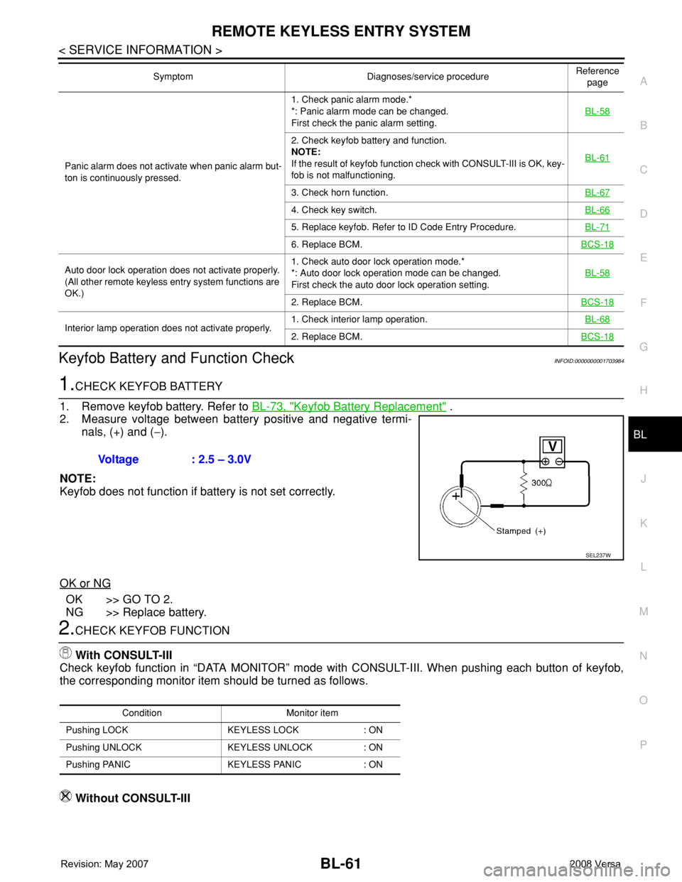
1.CHECK KEYFOB BATTERY
1. Remove keyfob battery. Refer to BL-73, "
Keyfob Battery Replacement" .
2. Measure voltage between battery positive and negative termi-
nals, (+) and (−).
NOTE:
Keyfob does not function if battery is not set correctly.
OK or NG
OK >> GO TO 2.
NG >> Replace battery.
2.CHECK KEYFOB FUNCTION
With CONSULT-III
Check keyfob function in “DATA MONITOR” mode with CONSULT-III. When pushing each button of keyfob,
the corresponding monitor item should be turned as follows.
Without CONSULT-III
Panic alarm does not activate when panic alarm but-
ton is continuously pressed.1. Check panic alarm mode.*
*: Panic alarm mode can be changed.
First check the panic alarm setting.BL-58
2. Check keyfob battery and function.
NOTE:
If the result of keyfob function check with CONSULT-III is OK, key-
fob is not malfunctioning.BL-61
3. Check horn function.BL-67
4. Check key switch.BL-66
5. Replace keyfob. Refer to ID Code Entry Procedure.BL-71
6. Replace BCM.BCS-18
Auto door lock operation does not activate properly.
(All other remote keyless entry system functions are
OK.)1. Check auto door lock operation mode.*
*: Auto door lock operation mode can be changed.
First check the auto door lock operation setting.BL-58
2. Replace BCM.BCS-18
Interior lamp operation does not activate properly.1. Check interior lamp operation.BL-682. Replace BCM.BCS-18
Symptom Diagnoses/service procedureReference
page
Voltage : 2.5 – 3.0V
SEL237W
Condition Monitor item
Pushing LOCK KEYLESS LOCK : ON
Pushing UNLOCK KEYLESS UNLOCK : ON
Pushing PANIC KEYLESS PANIC : ON
Page 502 of 2771
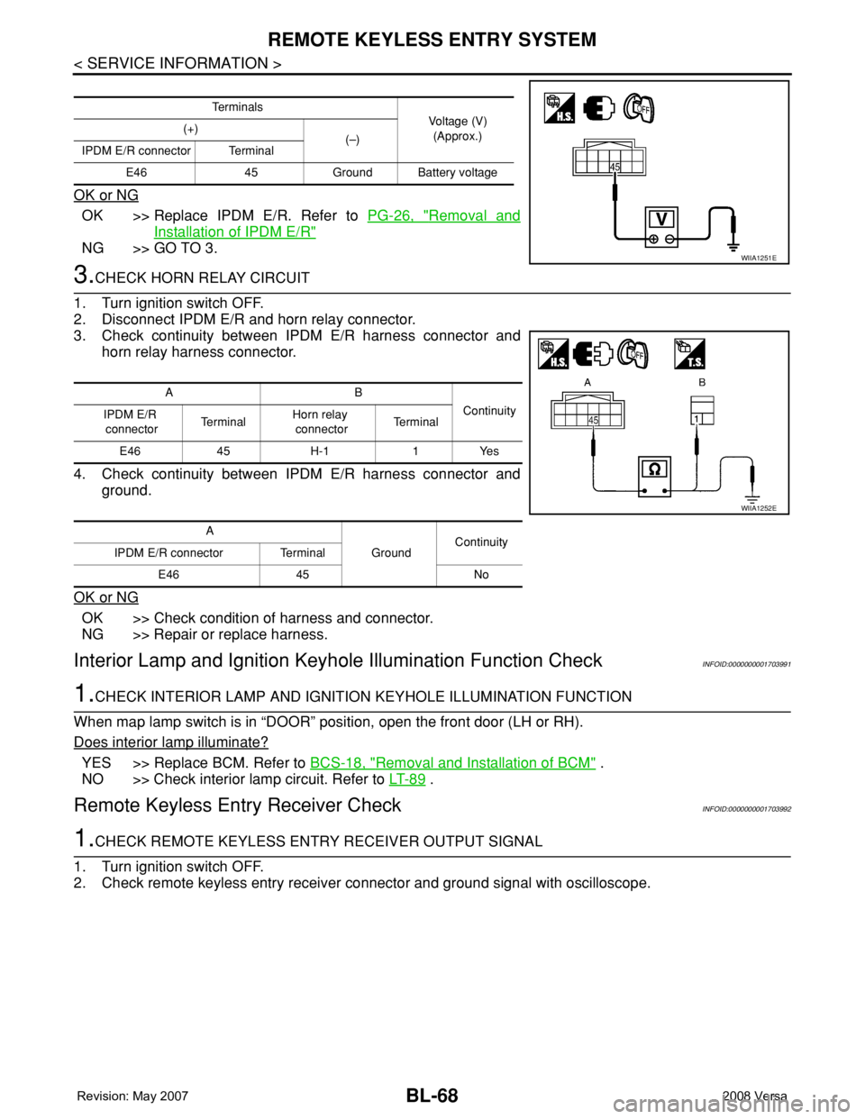
BL-68
< SERVICE INFORMATION >
REMOTE KEYLESS ENTRY SYSTEM
OK or NG
OK >> Replace IPDM E/R. Refer to PG-26, "Removal and
Installation of IPDM E/R"
NG >> GO TO 3.
3.CHECK HORN RELAY CIRCUIT
1. Turn ignition switch OFF.
2. Disconnect IPDM E/R and horn relay connector.
3. Check continuity between IPDM E/R harness connector and
horn relay harness connector.
4. Check continuity between IPDM E/R harness connector and
ground.
OK or NG
OK >> Check condition of harness and connector.
NG >> Repair or replace harness.
Interior Lamp and Ignition Keyhole Illumination Function CheckINFOID:0000000001703991
1.CHECK INTERIOR LAMP AND IGNITION KEYHOLE ILLUMINATION FUNCTION
When map lamp switch is in “DOOR” position, open the front door (LH or RH).
Does interior lamp illuminate?
YES >> Replace BCM. Refer to BCS-18, "Removal and Installation of BCM" .
NO >> Check interior lamp circuit. Refer to LT- 8 9
.
Remote Keyless Entry Receiver CheckINFOID:0000000001703992
1.CHECK REMOTE KEYLESS ENTRY RECEIVER OUTPUT SIGNAL
1. Turn ignition switch OFF.
2. Check remote keyless entry receiver connector and ground signal with oscilloscope.
Te r m i n a l s
Voltage (V)
(Approx.) (+)
(–)
IPDM E/R connector Terminal
E46 45 Ground Battery voltage
WIIA1251E
AB
Continuity
IPDM E/R
connectorTe r m i n a lHorn relay
connectorTe r m i n a l
E46 45 H-1 1 Yes
A
GroundContinuity
IPDM E/R connector Terminal
E46 45 No
WIIA1252E