oil change NISSAN TIIDA 2008 Service Repair Manual
[x] Cancel search | Manufacturer: NISSAN, Model Year: 2008, Model line: TIIDA, Model: NISSAN TIIDA 2008Pages: 2771, PDF Size: 60.61 MB
Page 7 of 2771

QUICK REFERENCE CHART: VERSA
2008
Fluids and LubricantsINFOID:0000000001903536
DescriptionCapacity (Approximate)
Liter US measure Imp measure
Fuel 52.0 13 3/4 gal 11 1/2 gal
Engine oil
Drain and refill With oil filter change 3.9 4 1/8 qt 3 3/8 qt
Without oil filter change 3.7 3 7/8 qt 3 1/4 qt
Dry engine (engine overhaul) 4.9 5 1/8 qt 4 3/8 qt
Cooling system
(with reservoir at max level) 6.8 7 1/4 qt 6 qt
Manual transaxle fluid (MTF) 2.0 4 1/4 pt 3 1/2 pt
Automatic transaxle fluid (ATF) 7.9 8 3/8 qt 7 qt
CVT fluid 8.3 8 3/4 qt 7 1/4 qt
Brake and clutch fluid — — —
Multi-purpose grease — — —
Windshield washer fluid 4.5 4 3/4 qt 4 qt
Air conditioning system refrigerant 0.45 ± 0.05 kg 0.99 ± 0.11 lb 0.99 ± 0.11 lb
Air conditioning system oil Typ e 1
120 m4.1 fl oz 4.2 fl oz
Typ e 2 100 m3.4 fl oz 3.5 fl oz
Page 79 of 2771
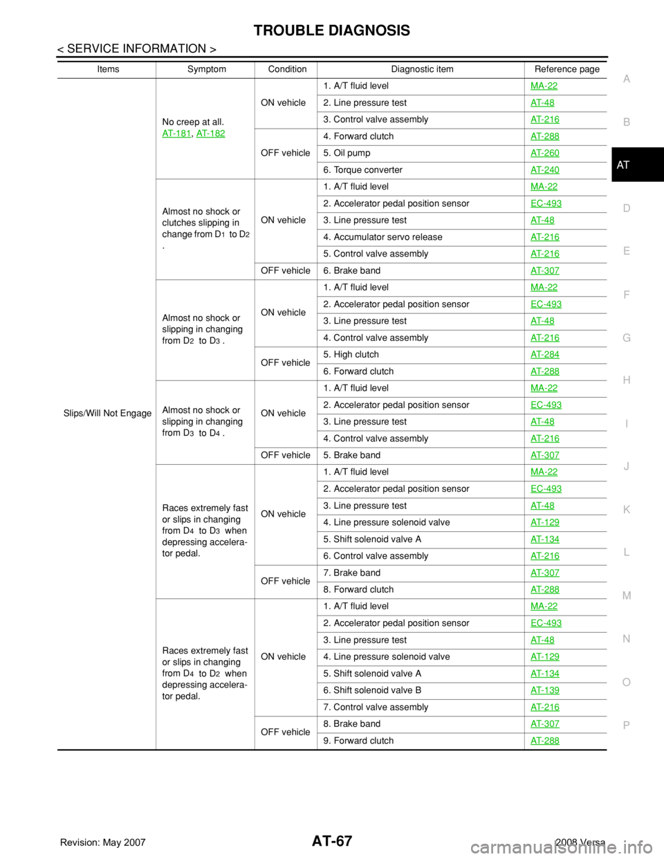
TROUBLE DIAGNOSIS
AT-67
< SERVICE INFORMATION >
D
E
F
G
H
I
J
K
L
MA
B
AT
N
O
P
Slips/Will Not EngageNo creep at all.
AT- 1 8 1
, AT- 1 8 2
ON vehicle1. A/T fluid levelMA-222. Line pressure testAT- 4 8
3. Control valve assemblyAT- 2 1 6
OFF vehicle4. Forward clutchAT- 2 8 85. Oil pumpAT- 2 6 0
6. Torque converterAT- 2 4 0
Almost no shock or
clutches slipping in
change from D
1 to D2
.ON vehicle1. A/T fluid levelMA-22
2. Accelerator pedal position sensorEC-493
3. Line pressure testAT- 4 8
4. Accumulator servo releaseAT- 2 1 6
5. Control valve assemblyAT- 2 1 6
OFF vehicle 6. Brake bandAT- 3 0 7
Almost no shock or
slipping in changing
from D
2 to D3 .ON vehicle1. A/T fluid levelMA-22
2. Accelerator pedal position sensorEC-493
3. Line pressure testAT- 4 8
4. Control valve assemblyAT- 2 1 6
OFF vehicle5. High clutchAT- 2 8 46. Forward clutchAT- 2 8 8
Almost no shock or
slipping in changing
from D
3 to D4 .ON vehicle1. A/T fluid levelMA-22
2. Accelerator pedal position sensorEC-493
3. Line pressure testAT- 4 8
4. Control valve assemblyAT- 2 1 6
OFF vehicle 5. Brake bandAT- 3 0 7
Races extremely fast
or slips in changing
from D
4 to D3 when
depressing accelera-
tor pedal.ON vehicle1. A/T fluid levelMA-22
2. Accelerator pedal position sensorEC-493
3. Line pressure testAT- 4 8
4. Line pressure solenoid valveAT- 1 2 9
5. Shift solenoid valve AAT- 1 3 4
6. Control valve assemblyAT- 2 1 6
OFF vehicle7. Brake bandAT- 3 0 78. Forward clutchAT- 2 8 8
Races extremely fast
or slips in changing
from D
4 to D2 when
depressing accelera-
tor pedal.ON vehicle1. A/T fluid levelMA-22
2. Accelerator pedal position sensorEC-493
3. Line pressure testAT- 4 8
4. Line pressure solenoid valveAT- 1 2 9
5. Shift solenoid valve AAT- 1 3 4
6. Shift solenoid valve BAT- 1 3 9
7. Control valve assemblyAT- 2 1 6
OFF vehicle8. Brake bandAT- 3 0 79. Forward clutchAT- 2 8 8
Items Symptom Condition Diagnostic item Reference page
Page 381 of 2771
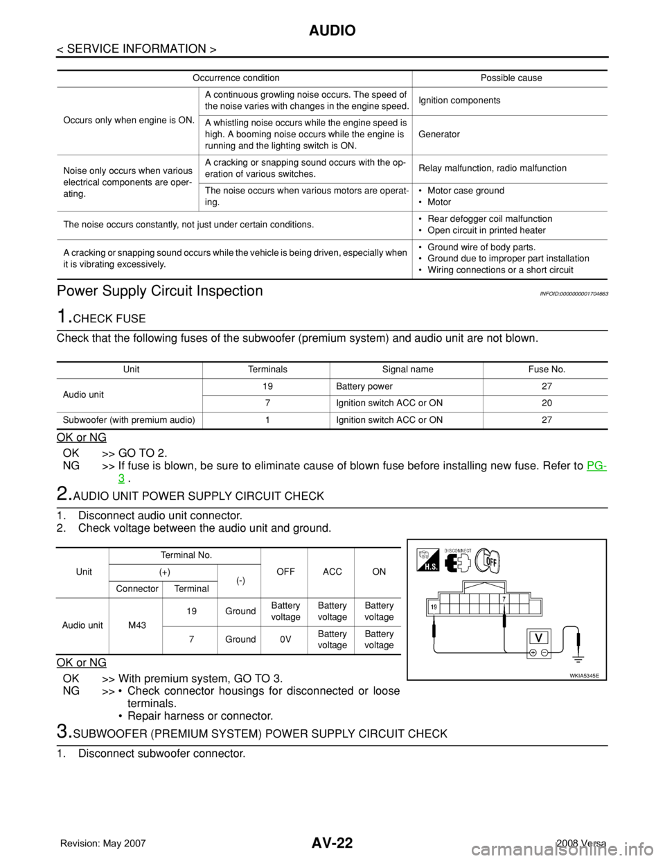
AV-22
< SERVICE INFORMATION >
AUDIO
Power Supply Circuit Inspection
INFOID:0000000001704663
1.CHECK FUSE
Check that the following fuses of the subwoofer (premium system) and audio unit are not blown.
OK or NG
OK >> GO TO 2.
NG >> If fuse is blown, be sure to eliminate cause of blown fuse before installing new fuse. Refer to PG-
3 .
2.AUDIO UNIT POWER SUPPLY CIRCUIT CHECK
1. Disconnect audio unit connector.
2. Check voltage between the audio unit and ground.
OK or NG
OK >> With premium system, GO TO 3.
NG >> • Check connector housings for disconnected or loose
terminals.
• Repair harness or connector.
3.SUBWOOFER (PREMIUM SYSTEM) POWER SUPPLY CIRCUIT CHECK
1. Disconnect subwoofer connector.
Occurrence condition Possible cause
Occurs only when engine is ON.A continuous growling noise occurs. The speed of
the noise varies with changes in the engine speed.Ignition components
A whistling noise occurs while the engine speed is
high. A booming noise occurs while the engine is
running and the lighting switch is ON.Generator
Noise only occurs when various
electrical components are oper-
ating.A cracking or snapping sound occurs with the op-
eration of various switches.Relay malfunction, radio malfunction
The noise occurs when various motors are operat-
ing.• Motor case ground
• Motor
The noise occurs constantly, not just under certain conditions.• Rear defogger coil malfunction
• Open circuit in printed heater
A cracking or snapping sound occurs while the vehicle is being driven, especially when
it is vibrating excessively.• Ground wire of body parts.
• Ground due to improper part installation
• Wiring connections or a short circuit
Unit Terminals Signal name Fuse No.
Audio unit19 Battery power 27
7 Ignition switch ACC or ON 20
Subwoofer (with premium audio) 1 Ignition switch ACC or ON 27
UnitTe r m i n a l N o .
OFF ACC ON (+)
(-)
Connector Terminal
Audio unit M4319 GroundBattery
voltageBattery
voltageBattery
voltage
7Ground0VBattery
voltageBattery
voltage
WKIA5345E
Page 843 of 2771

CVT-4
DTC P1740 LOCK-UP SELECT SOLENOID
VALVE CIRCUIT ..............................................
132
Description .............................................................132
CONSULT-III Reference Value in Data Monitor
Mode ......................................................................
132
On Board Diagnosis Logic .....................................132
Possible Cause ......................................................132
DTC Confirmation Procedure ................................132
Wiring Diagram - CVT - L/USSV ............................133
Diagnosis Procedure .............................................134
Component Inspection ...........................................135
DTC P1745 LINE PRESSURE CONTROL ......136
Description .............................................................136
On Board Diagnosis Logic .....................................136
Possible Cause ......................................................136
DTC Confirmation Procedure ................................136
Diagnosis Procedure .............................................136
DTC P1777 STEP MOTOR - CIRCUIT ............137
Description .............................................................137
CONSULT-III Reference Value in Data Monitor
Mode ......................................................................
137
On Board Diagnosis Logic .....................................137
Possible Cause ......................................................137
DTC Confirmation Procedure ................................137
Wiring Diagram - CVT - STM .................................138
Diagnosis Procedure .............................................139
Component Inspection ...........................................140
DTC P1778 STEP MOTOR - FUNCTION ........141
Description .............................................................141
CONSULT-III Reference Value in Data Monitor
Mode ......................................................................
141
On Board Diagnosis Logic .....................................141
Possible Cause ......................................................141
DTC Confirmation Procedure ................................141
Diagnosis Procedure .............................................142
OVERDRIVE CONTROL SWITCH ..................143
Description .............................................................143
CONSULT-III Reference Value in Data Monitor
Mode ......................................................................
143
Wiring Diagram - CVT - ODSW .............................144
Diagnosis Procedure .............................................144
Component Inspection ...........................................146
SHIFT POSITION INDICATOR CIRCUIT ........148
Description .............................................................148
CONSULT-III Reference Value in Data Monitor
Mode ......................................................................
148
Diagnosis Procedure .............................................148
TROUBLE DIAGNOSIS FOR SYMPTOMS .....149
Wiring Diagram - CVT - NONDTC .........................149
O/D OFF Indicator Lamp Does Not Come On ......151
Engine Cannot Be Started in "P" and "N" Position .153
In "P" Position, Vehicle Moves Forward or Back-
ward When Pushed ...............................................
153
In "N" Position, Vehicle Moves ..............................154
Large Shock "N" → "R" Position ...........................154
Vehicle Does Not Creep Backward in "R" Position .155
Vehicle Does Not Creep Forward in "D" or "L" Po-
sition ......................................................................
156
Vehicle Speed Does Not Change in "L" Position ..157
Vehicle Speed Does Not Change in overdrive-off
mode .....................................................................
158
Vehicle Speed Does Not Change in "D" Position .159
Vehicle Does Not Decelerate by Engine Brake ....159
TRANSMISSION CONTROL MODULE ...........161
Removal and Installation .......................................161
CVT SHIFT LOCK SYSTEM .............................162
Description ............................................................162
Shift Lock System Electrical Parts Location ..........162
Wiring Diagram - CVT - SHIFT .............................163
Diagnosis Procedure .............................................163
SHIFT CONTROL SYSTEM .............................167
Removal and Installation .......................................167
Control Device Disassembly and Assembly .........170
Selector Lever Knob Removal and Installation .....170
Adjustment of CVT Position ..................................171
Checking of CVT Position .....................................171
KEY INTERLOCK CABLE ...............................173
Removal and Installation .......................................173
AIR BREATHER HOSE ....................................176
Removal and Installation .......................................176
DIFFERENTIAL SIDE OIL SEAL .....................177
Removal and Installation .......................................177
TRANSAXLE ASSEMBLY ...............................178
Removal and Installation .......................................178
SERVICE DATA AND SPECIFICATIONS
(SDS) ................................................................
181
General Specification ............................................181
Vehicle Speed When Shifting Gears .....................181
Stall Speed ............................................................181
Line Pressure ........................................................181
Solenoid Valves ....................................................182
CVT Fluid Temperature Sensor ............................182
Primary Speed Sensor ..........................................182
Secondary Speed Sensor .....................................182
Removal and Installation .......................................182
Page 868 of 2771

TROUBLE DIAGNOSIS
CVT-29
< SERVICE INFORMATION >
D
E
F
G
H
I
J
K
L
MA
B
CVT
N
O
P
TROUBLE DIAGNOSIS
DTC Inspection Priority ChartINFOID:0000000001703451
If some DTCs are displayed at the same time, perform inspections one by one based on the following priority
chart.
NOTE:
If DTC “U1000 CAN COMM CIRCUIT” is displayed with other DTCs, first perform the trouble diagnosis
for “DTC U1000 CAN COMMUNICATION LINE”. Refer to CVT-56
.
Fail-SafeINFOID:0000000001703452
The TCM has an electrical fail-safe mode. This mode makes it possible to operate even if there is an error in a
main electronic control input/output signal circuit.
FAIL-SAFE FUNCTION
If any malfunction occurs in a sensor or solenoid, this function controls the CVT to make driving possible.
Output Speed Sensor (Secondary Speed Sensor)
The shift pattern is changed in accordance with throttle position when an unexpected signal is sent from the
output speed sensor (secondary speed sensor) to the TCM. The overdrive-off mode is inhibited, and the tran-
saxle is put in “D”.
Input Speed Sensor (Primary Speed Sensor)
The shift pattern is changed in accordance with throttle position and secondary speed (vehicle speed) when
an unexpected signal is sent from the input speed sensor (primary speed sensor) to the TCM. The sport mode
is inhibited, and the transaxle is put in “D”.
PNP Switch
If an unexpected signal is sent from the PNP switch to the TCM, the transaxle is put in “D”.
CVT Fluid Temperature Sensor
If an unexpected signal is sent from the CVT fluid temperature sensor to the TCM, the gear ratio in use before
receiving the unexpected signal is maintained or the gear ratio is controlled to keep engine speed under 3500
rpm.
Transmission Fluid Pressure Sensor A (Secondary Pressure Sensor)
• If an unexpected signal is sent from the transmission fluid pressure sensor A (secondary pressure sensor) to
the TCM, the secondary pressure feedback control is stopped and the offset value obtained before the non-
standard condition occurs is used to control line pressure.
• If transmission fluid pressure sensor A (secondary pressure sensor) error signal is input to TCM, secondary
pressure feedback control stops, but line pressure is controlled normally.
Pressure Control Solenoid A (Line Pressure Solenoid)
If an unexpected signal is sent from the solenoid to the TCM, the pressure control solenoid A (line pressure
solenoid) is turned OFF to achieve the maximum fluid pressure.
Pressure Control Solenoid B (Secondary Pressure Solenoid)
If an unexpected signal is sent from the solenoid to the TCM, the pressure control solenoid B (secondary pres-
sure solenoid) is turned OFF to achieve the maximum fluid pressure.
Torque Converter Clutch Solenoid
If an unexpected signal is sent from the solenoid to the TCM, the torque converter clutch solenoid is turned
OFF to cancel the lock-up.
Ste p M oto r
If an unexpected signal is sent from the step motor to the TCM, the step motor coil phases “A” through “D” are
all turned OFF to hold the gear ratio used right before the non-standard condition occurred.
CVT Lock-up Select Solenoid
Priority Detected items (DTC)
1 U1000 CAN communication line
2 Except above
Page 882 of 2771
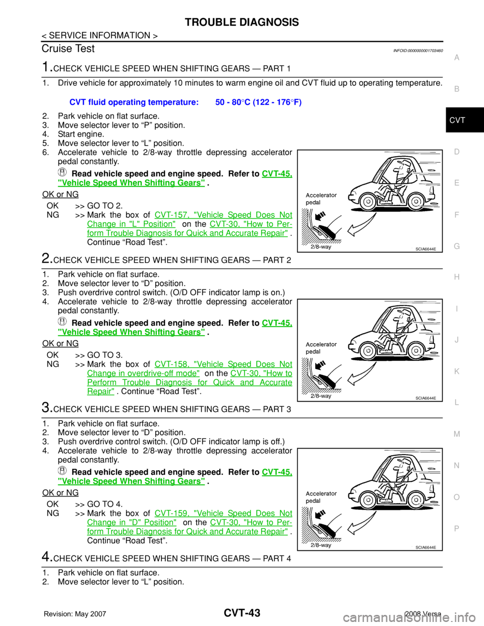
TROUBLE DIAGNOSIS
CVT-43
< SERVICE INFORMATION >
D
E
F
G
H
I
J
K
L
MA
B
CVT
N
O
P
Cruise TestINFOID:0000000001703460
1.CHECK VEHICLE SPEED WHEN SHIFTING GEARS — PART 1
1. Drive vehicle for approximately 10 minutes to warm engine oil and CVT fluid up to operating temperature.
2. Park vehicle on flat surface.
3. Move selector lever to “P” position.
4. Start engine.
5. Move selector lever to “L” position.
6. Accelerate vehicle to 2/8-way throttle depressing accelerator
pedal constantly.
Read vehicle speed and engine speed. Refer to CVT-45,
"Vehicle Speed When Shifting Gears" .
OK or NG
OK >> GO TO 2.
NG >> Mark the box of CVT-157, "
Vehicle Speed Does Not
Change in "L" Position" on the CVT-30, "How to Per-
form Trouble Diagnosis for Quick and Accurate Repair" .
Continue “Road Test”.
2.CHECK VEHICLE SPEED WHEN SHIFTING GEARS — PART 2
1. Park vehicle on flat surface.
2. Move selector lever to “D” position.
3. Push overdrive control switch. (O/D OFF indicator lamp is on.)
4. Accelerate vehicle to 2/8-way throttle depressing accelerator
pedal constantly.
Read vehicle speed and engine speed. Refer to CVT-45,
"Vehicle Speed When Shifting Gears" .
OK or NG
OK >> GO TO 3.
NG >> Mark the box of CVT-158, "
Vehicle Speed Does Not
Change in overdrive-off mode" on the CVT-30, "How to
Perform Trouble Diagnosis for Quick and Accurate
Repair" . Continue “Road Test”.
3.CHECK VEHICLE SPEED WHEN SHIFTING GEARS — PART 3
1. Park vehicle on flat surface.
2. Move selector lever to “D” position.
3. Push overdrive control switch. (O/D OFF indicator lamp is off.)
4. Accelerate vehicle to 2/8-way throttle depressing accelerator
pedal constantly.
Read vehicle speed and engine speed. Refer to CVT-45,
"Vehicle Speed When Shifting Gears" .
OK or NG
OK >> GO TO 4.
NG >> Mark the box of CVT-159, "
Vehicle Speed Does Not
Change in "D" Position" on the CVT-30, "How to Per-
form Trouble Diagnosis for Quick and Accurate Repair" .
Continue “Road Test”.
4.CHECK VEHICLE SPEED WHEN SHIFTING GEARS — PART 4
1. Park vehicle on flat surface.
2. Move selector lever to “L” position. CVT fluid operating temperature: 50 - 80°C (122 - 176°F)
SCIA6644E
SCIA6644E
SCIA6644E
Page 888 of 2771

TROUBLE DIAGNOSIS
CVT-49
< SERVICE INFORMATION >
D
E
F
G
H
I
J
K
L
MA
B
CVT
N
O
P
*: Models without ABS does not indicate.
WORK SUPPORT MODE
Display Item List
INH SW3Selector lever in “D” and “L” positions ON
Selector lever in “P”, “R” and “N” positions OFF
INH SW2Selector lever in “N”, “D” and “L” positions ON
Selector lever in “P” and “R” positions OFF
INH SW1Selector lever in “R”, “N” and “D” positions ON
Selector lever in “P” and “L” positions OFF
BRAKE SWDepressed brake pedal ON
Released brake pedal OFF
FULL SWFully depressed accelerator pedal ON
Released accelerator pedal OFF
IDLE SWReleased accelerator pedal ON
Fully depressed accelerator pedal OFF
SPORT MODE SWWhile pushing overdrive cancel switch ON
Other conditions OFF
INDDRNGSelector lever in “D” position ON
Selector lever in other positions OFF
INDLRNGSelector lever in “L” position ON
Selector lever in other positions OFF
INDNRNGSelector lever in “N” position ON
Selector lever in other positions OFF
INDRRNGSelector lever in “R” position ON
Selector lever in other positions OFF
INDPRNGSelector lever in “P” position ON
Selector lever in other positions OFF
SMCOIL D
During driving Changes ON ⇔ OFF. SMCOIL C
SMCOIL B
SMCOIL A
LUSEL SOL OUTSelector lever in “P” and “N” positions ON
Wait at least for 5 seconds with the selector lever
in “R”, “D” and “L” positionsOFF
STRTR RLY OUTSelector lever in “P” and “N” positions ON
Selector lever in other positions OFF
STRTR RLY MONSelector lever in “P” and “N” positions ON
Selector lever in other positions OFF
RANGESelector lever in “N” or “P” position. N·P
Selector lever in “R” position. R
Selector lever in “D” position. D
Selector lever in “L” position. L Item name Condition Display value (Approx.)
Page 891 of 2771
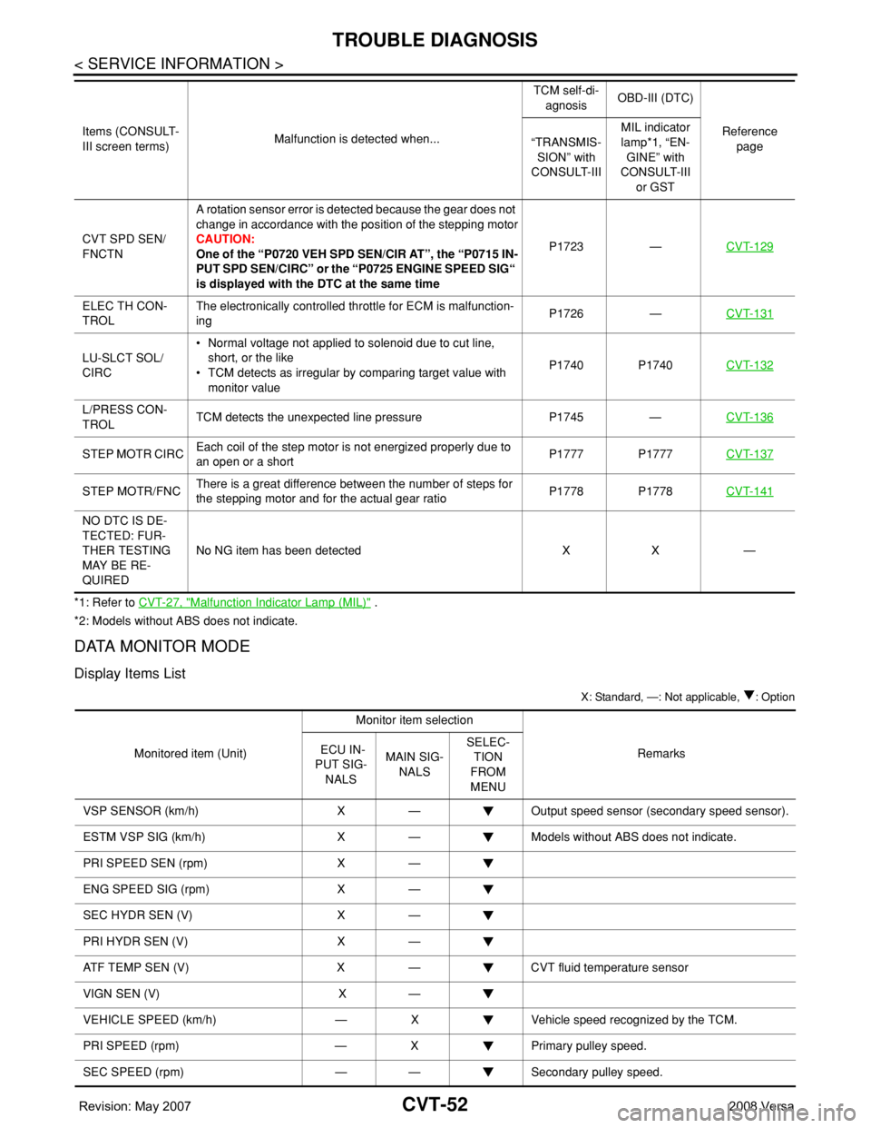
CVT-52
< SERVICE INFORMATION >
TROUBLE DIAGNOSIS
*1: Refer to CVT-27, "Malfunction Indicator Lamp (MIL)" .
*2: Models without ABS does not indicate.
DATA MONITOR MODE
Display Items List
X: Standard, —: Not applicable, : Option
CVT SPD SEN/
FNCTNA rotation sensor error is detected because the gear does not
change in accordance with the position of the stepping motor
CAUTION:
One of the “P0720 VEH SPD SEN/CIR AT”, the “P0715 IN-
PUT SPD SEN/CIRC” or the “P0725 ENGINE SPEED SIG“
is displayed with the DTC at the same timeP1723 —CVT-129
ELEC TH CON-
TROLThe electronically controlled throttle for ECM is malfunction-
ingP1726 —CVT-131
LU-SLCT SOL/
CIRC• Normal voltage not applied to solenoid due to cut line,
short, or the like
• TCM detects as irregular by comparing target value with
monitor valueP1740 P1740CVT-132
L/PRESS CON-
TROLTCM detects the unexpected line pressure P1745 —CVT-136
STEP MOTR CIRCEach coil of the step motor is not energized properly due to
an open or a shortP1777 P1777CVT-137
STEP MOTR/FNCThere is a great difference between the number of steps for
the stepping motor and for the actual gear ratioP1778 P1778CVT-141
NO DTC IS DE-
TECTED: FUR-
THER TESTING
MAY BE RE-
QUIREDNo NG item has been detected X X — Items (CONSULT-
III screen terms)Malfunction is detected when...TCM self-di-
agnosisOBD-III (DTC)
Reference
page “TRANSMIS-
SION” with
CONSULT-IIIMIL indicator
lamp*1, “EN-
GINE” with
CONSULT-III
or GST
Monitored item (Unit)Monitor item selection
Remarks ECU IN-
PUT SIG-
NALSMAIN SIG-
NALSSELEC-
TION
FROM
MENU
VSP SENSOR (km/h) X — Output speed sensor (secondary speed sensor).
ESTM VSP SIG (km/h) X — Models without ABS does not indicate.
PRI SPEED SEN (rpm) X —
ENG SPEED SIG (rpm) X —
SEC HYDR SEN (V) X —
PRI HYDR SEN (V) X —
ATF TEMP SEN (V) X — CVT fluid temperature sensor
VIGN SEN (V) X —
VEHICLE SPEED (km/h) — X Vehicle speed recognized by the TCM.
PRI SPEED (rpm) — X Primary pulley speed.
SEC SPEED (rpm) — — Secondary pulley speed.
Page 976 of 2771
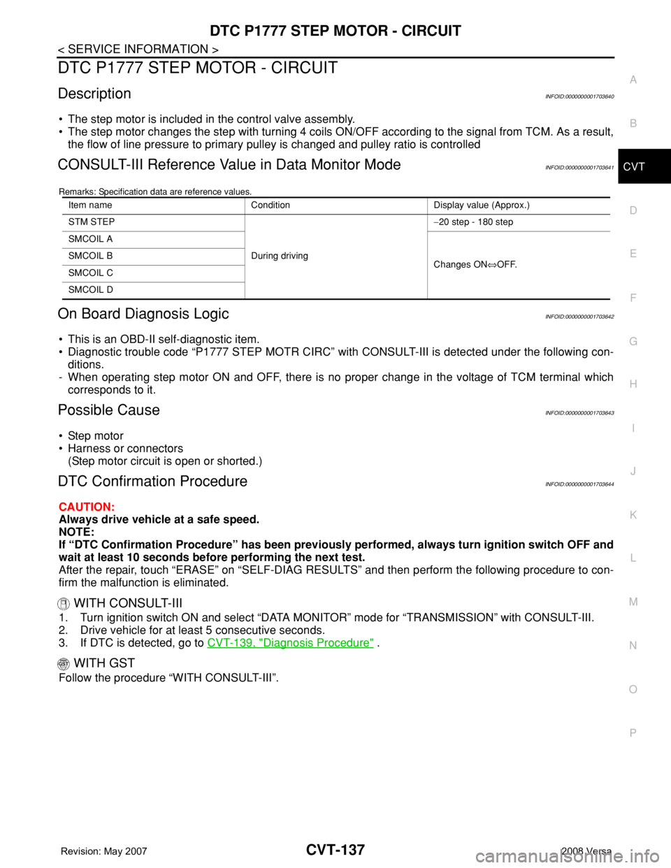
DTC P1777 STEP MOTOR - CIRCUIT
CVT-137
< SERVICE INFORMATION >
D
E
F
G
H
I
J
K
L
MA
B
CVT
N
O
P
DTC P1777 STEP MOTOR - CIRCUIT
DescriptionINFOID:0000000001703640
• The step motor is included in the control valve assembly.
• The step motor changes the step with turning 4 coils ON/OFF according to the signal from TCM. As a result,
the flow of line pressure to primary pulley is changed and pulley ratio is controlled
CONSULT-III Reference Value in Data Monitor ModeINFOID:0000000001703641
Remarks: Specification data are reference values.
On Board Diagnosis LogicINFOID:0000000001703642
• This is an OBD-II self-diagnostic item.
• Diagnostic trouble code “P1777 STEP MOTR CIRC” with CONSULT-III is detected under the following con-
ditions.
- When operating step motor ON and OFF, there is no proper change in the voltage of TCM terminal which
corresponds to it.
Possible CauseINFOID:0000000001703643
• Step motor
• Harness or connectors
(Step motor circuit is open or shorted.)
DTC Confirmation ProcedureINFOID:0000000001703644
CAUTION:
Always drive vehicle at a safe speed.
NOTE:
If “DTC Confirmation Procedure” has been previously performed, always turn ignition switch OFF and
wait at least 10 seconds before performing the next test.
After the repair, touch “ERASE” on “SELF-DIAG RESULTS” and then perform the following procedure to con-
firm the malfunction is eliminated.
WITH CONSULT-III
1. Turn ignition switch ON and select “DATA MONITOR” mode for “TRANSMISSION” with CONSULT-III.
2. Drive vehicle for at least 5 consecutive seconds.
3. If DTC is detected, go to CVT-139, "
Diagnosis Procedure" .
WITH GST
Follow the procedure “WITH CONSULT-III”.
Item name Condition Display value (Approx.)
STM STEP
During driving−20 step - 180 step
SMCOIL A
Changes ON⇔OFF. SMCOIL B
SMCOIL C
SMCOIL D
Page 978 of 2771
DTC P1777 STEP MOTOR - CIRCUIT
CVT-139
< SERVICE INFORMATION >
D
E
F
G
H
I
J
K
L
MA
B
CVT
N
O
P
Diagnosis ProcedureINFOID:0000000001703646
1.CHECK INPUT SIGNALS
With CONSULT-III
1. Start engine.
2. Select “SELECTION FROM MENU” in “DATA MONITOR” mode for “TRANSMISSION” with CONSULT-III.
3. Start vehicle and read out the value of “STM STEP”, “SMCOIL A”, “SMCOIL B”, “SMCOIL C”, and
“SMCOIL D”.
OK or NG
OK >> GO TO 4.
NG >> GO TO 2.
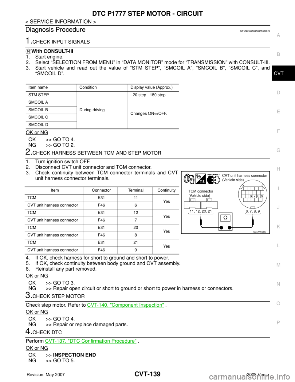
2.CHECK HARNESS BETWEEN TCM AND STEP MOTOR
1. Turn ignition switch OFF.
2. Disconnect CVT unit connector and TCM connector.
3. Check continuity between TCM connector terminals and CVT
unit harness connector terminals.
4. If OK, check harness for short to ground and short to power.
5. If OK, check continuity between body ground and CVT assembly.
6. Reinstall any part removed.
OK or NG
OK >> GO TO 3.
NG >> Repair open circuit or short to ground or short to power in harness or connectors.
3.CHECK STEP MOTOR
Check step motor. Refer to CVT-140, "
Component Inspection" .
OK or NG
OK >> GO TO 4.
NG >> Repair or replace damaged parts.
4.CHECK DTC
Perform CVT-137, "
DTC Confirmation Procedure" .
OK or NG
OK >>INSPECTION END
NG >> GO TO 5.
Item name Condition Display value (Approx.)
STM STEP
During driving−20 step - 180 step
SMCOIL A
Changes ON⇔OFF. SMCOIL B
SMCOIL C
SMCOIL D
Item Connector Terminal Continuity
TCM E31 11
Ye s
CVT unit harness connector F46 6
TCM E31 12
Ye s
CVT unit harness connector F46 7
TCM E31 20
Ye s
CVT unit harness connector F46 8
TCM E31 21
Ye s
CVT unit harness connector F46 9
SCIA4695E