speedometer NISSAN TIIDA 2008 Service Repair Manual
[x] Cancel search | Manufacturer: NISSAN, Model Year: 2008, Model line: TIIDA, Model: NISSAN TIIDA 2008Pages: 2771, PDF Size: 60.61 MB
Page 85 of 2771
TROUBLE DIAGNOSIS
AT-73
< SERVICE INFORMATION >
D
E
F
G
H
I
J
K
L
MA
B
AT
N
O
P
*1: These terminals are connected to the data link connector.
*2: These terminals are connected to the ECM.
CONSULT-III Function (A/T)INFOID:0000000001703193
CONSULT-III can display each diagnostic item using the diagnostic test models shown following.
FUNCTION
CONSULT-III REFERENCE VALUE
NOTICE:
1. The CONSULT-III electrically displays shift timing and lock-up timing (that is, operation timing of each
solenoid).
Check for time difference between actual shift timing and the CONSULT-III display. If the difference is
noticeable, mechanical parts (except solenoids, sensors, etc.) may be malfunctioning. Check mechanical
parts using applicable diagnostic procedures.
2. Shift schedule (which implies gear position) displayed on CONSULT-III and that indicated in Service Man-
ual may differ slightly. This occurs because of the following reasons:
- Actual shift schedule has more or less tolerance or allowance,
- Shift schedule indicated in Service Manual refers to the point where shifts start, and
- Gear position displayed on CONSULT-III indicates the point where shifts are completed.
3. Shift solenoid valve “A” or “B” is displayed on CONSULT-III at the start of shifting. Gear position is dis-
played upon completion of shifting (which is computed by TCM).
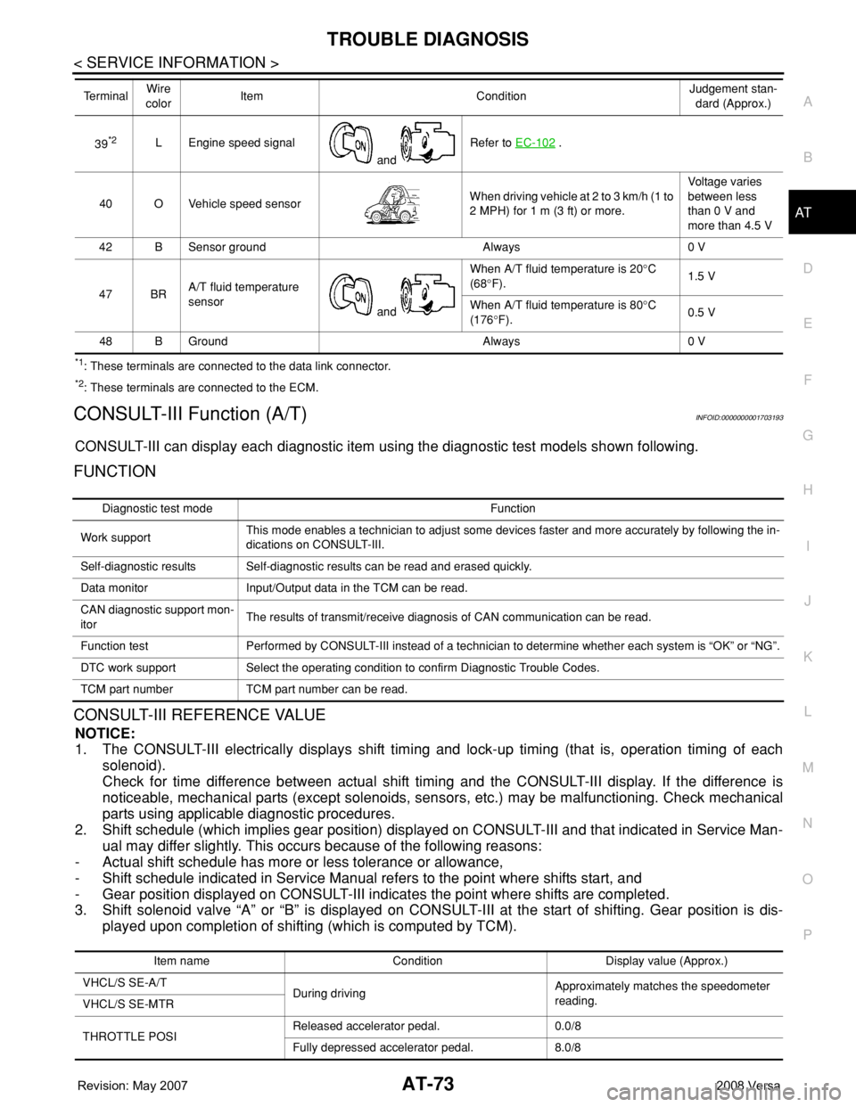
39*2L Engine speed signal
and Refer to EC-102 .
40 O Vehicle speed sensorWhen driving vehicle at 2 to 3 km/h (1 to
2 MPH) for 1 m (3 ft) or more.Voltage varies
between less
than 0 V and
more than 4.5 V
42 B Sensor ground Always 0 V
47 BRA/T fluid temperature
sensor
and When A/T fluid temperature is 20°C
(68°F).1.5 V
When A/T fluid temperature is 80°C
(176°F).0.5 V
48 B Ground Always 0 V Te r m i n a lWire
colorItem ConditionJudgement stan-
dard (Approx.)
Diagnostic test mode Function
Work supportThis mode enables a technician to adjust some devices faster and more accurately by following the in-
dications on CONSULT-III.
Self-diagnostic results Self-diagnostic results can be read and erased quickly.
Data monitor Input/Output data in the TCM can be read.
CAN diagnostic support mon-
itorThe results of transmit/receive diagnosis of CAN communication can be read.
Function test Performed by CONSULT-III instead of a technician to determine whether each system is “OK” or “NG”.
DTC work support Select the operating condition to confirm Diagnostic Trouble Codes.
TCM part number TCM part number can be read.
Item name Condition Display value (Approx.)
VHCL/S SE-A/T
During drivingApproximately matches the speedometer
reading.
VHCL/S SE-MTR
THROTTLE POSIReleased accelerator pedal. 0.0/8
Fully depressed accelerator pedal. 8.0/8
Page 86 of 2771

AT-74
< SERVICE INFORMATION >
TROUBLE DIAGNOSIS
FLUID TEMP SE When A/T fluid temperature is 20°C (68°F). 1.5 V
When A/T fluid temperature is 80°C (176°F). 0.5 V
BATTERY VOLT When turning ignition switch to “ON”. Battery voltage
ENGINE SPEED Engine runningApproximately matches the tachometer
reading.
TURBINE REV During driving (lock-up ON) Approximately matches the engine speed.
OVERDRIVE SWWhen overdrive control switch is depressed. ON
When overdrive control switch is released. OFF
PN POSI SWWhen setting selector lever to “N” or “P” position. ON
When setting selector lever to other positions. OFF
R POSITION SWWhen setting selector lever to “R” position. ON
When setting selector lever to other positions. OFF
D POSITION SWWhen setting selector lever to “D” position. ON
When setting selector lever to other positions. OFF
2 POSITION SWWhen setting selector lever to “2” position. ON
When setting selector lever to other positions. OFF
1 POSITION SWWhen setting selector lever to “1” position. ON
When setting selector lever to other positions. OFF
CLOSED THL/SWReleased accelerator pedal. ON
Depressed accelerator pedal. OFF
W/O THRL/P-SWFully depressed accelerator pedal. ON
Released accelerator pedal. OFF
SHIFT S/V AWhen shift solenoid valve A operates.
(When driving in “D
1” or “D4”.)ON
When shift solenoid valve A does not operate.
(When driving in “D
2” or “D3”.)OFF
SHIFT S/V BWhen shift solenoid valve B operates.
(When driving in “D
1” or “D2”.)ON
When shift solenoid valve B does not operate.
(When driving in “D
3” or “D4”.)OFF
OVERRUN/C S/VWhen overrun clutch solenoid valve operates.
(When overrun clutch disengaged. Refer to AT-
19 .)ON
When overrun clutch solenoid valve does not
operate. (When overrun clutch engaged. Refer
to AT- 1 9
.)OFF
BRAKE SWDepressed brake pedal. ON
Released brake pedal. OFF
GEAR During driving 1, 2, 3, 4
SLCT LVR POSIWhen setting selector lever to “N” or “P” posi-
tions.N · P
When setting selector lever to “R” position. R
When setting selector lever to “D” position. D
When setting selector lever to “2” position. 2
When setting selector lever to “1” position. 1
VEHICLE SPEED During drivingApproximately matches the speedometer
reading. Item name Condition Display value (Approx.)
Page 108 of 2771
AT-96
< SERVICE INFORMATION >
DTC P0720 VEHICLE SPEED SENSOR A/T (REVOLUTION SENSOR)
DTC P0720 VEHICLE SPEED SENSOR A/T (REVOLUTION SENSOR)
DescriptionINFOID:0000000001703217
The revolution sensor detects the revolution of the idler gear parking pawl lock gear and emits a pulse signal.
The pulse signal is sent to the TCM which converts it into vehicle speed.
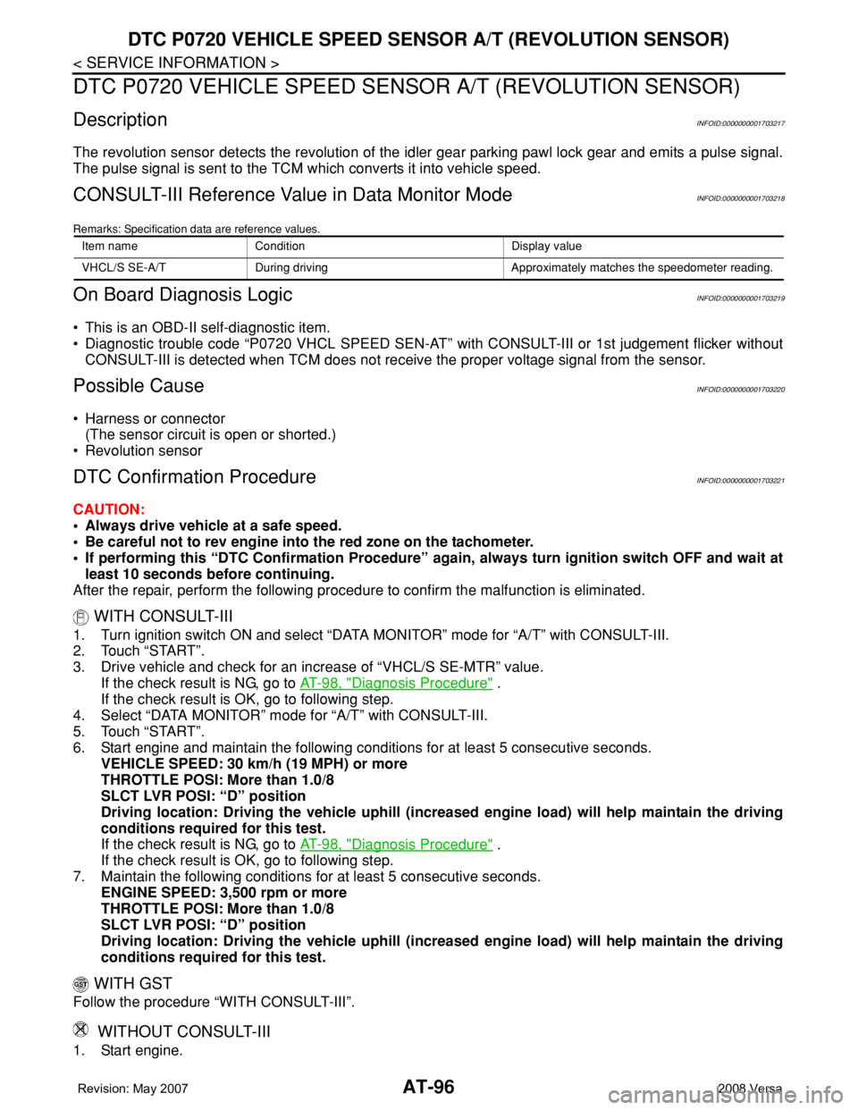
CONSULT-III Reference Value in Data Monitor ModeINFOID:0000000001703218
Remarks: Specification data are reference values.
On Board Diagnosis LogicINFOID:0000000001703219
• This is an OBD-II self-diagnostic item.
• Diagnostic trouble code “P0720 VHCL SPEED SEN-AT” with CONSULT-III or 1st judgement flicker without
CONSULT-III is detected when TCM does not receive the proper voltage signal from the sensor.
Possible CauseINFOID:0000000001703220
• Harness or connector
(The sensor circuit is open or shorted.)
• Revolution sensor
DTC Confirmation ProcedureINFOID:0000000001703221
CAUTION:
• Always drive vehicle at a safe speed.
• Be careful not to rev engine into the red zone on the tachometer.
• If performing this “DTC Confirmation Procedure” again, always turn ignition switch OFF and wait at
least 10 seconds before continuing.
After the repair, perform the following procedure to confirm the malfunction is eliminated.
WITH CONSULT-III
1. Turn ignition switch ON and select “DATA MONITOR” mode for “A/T” with CONSULT-III.
2. Touch “START”.
3. Drive vehicle and check for an increase of “VHCL/S SE-MTR” value.
If the check result is NG, go to AT-98, "
Diagnosis Procedure" .
If the check result is OK, go to following step.
4. Select “DATA MONITOR” mode for “A/T” with CONSULT-III.
5. Touch “START”.
6. Start engine and maintain the following conditions for at least 5 consecutive seconds.
VEHICLE SPEED: 30 km/h (19 MPH) or more
THROTTLE POSI: More than 1.0/8
SLCT LVR POSI: “D” position
Driving location: Driving the vehicle uphill (increased engine load) will help maintain the driving
conditions required for this test.
If the check result is NG, go to AT-98, "
Diagnosis Procedure" .
If the check result is OK, go to following step.
7. Maintain the following conditions for at least 5 consecutive seconds.
ENGINE SPEED: 3,500 rpm or more
THROTTLE POSI: More than 1.0/8
SLCT LVR POSI: “D” position
Driving location: Driving the vehicle uphill (increased engine load) will help maintain the driving
conditions required for this test.
WITH GST
Follow the procedure “WITH CONSULT-III”.
WITHOUT CONSULT-III
1. Start engine.
Item name Condition Display value
VHCL/S SE-A/T During driving Approximately matches the speedometer reading.
Page 161 of 2771
DTC VEHICLE SPEED SENSOR MTR
AT-149
< SERVICE INFORMATION >
D
E
F
G
H
I
J
K
L
MA
B
AT
N
O
P
DTC VEHICLE SPEED SENSOR MTR
DescriptionINFOID:0000000001703298
The vehicle speed sensor·MTR is built into the speedometer assembly. The sensor functions as an auxiliary
device to the revolution sensor when it is malfunctioning. The TCM will then use a signal sent from the vehicle
speed sensor·MTR.
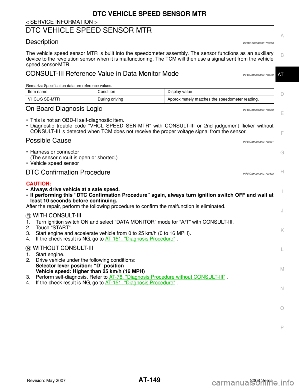
CONSULT-III Reference Value in Data Monitor ModeINFOID:0000000001703299
Remarks: Specification data are reference values.
On Board Diagnosis LogicINFOID:0000000001703300
• This is not an OBD-II self-diagnostic item.
• Diagnostic trouble code “VHCL SPEED SEN-MTR” with CONSULT-III or 2nd judgement flicker without
CONSULT-III is detected when TCM does not receive the proper voltage signal from the sensor.
Possible CauseINFOID:0000000001703301
• Harness or connector
(The sensor circuit is open or shorted.)
• Vehicle speed sensor
DTC Confirmation ProcedureINFOID:0000000001703302
CAUTION:
• Always drive vehicle at a safe speed.
• If performing this “DTC Confirmation Procedure” again, always turn ignition switch OFF and wait at
least 10 seconds before continuing.
After the repair, perform the following procedure to confirm the malfunction is eliminated.
WITH CONSULT-III
1. Turn ignition switch ON and select “DATA MONITOR” mode for “A/T” with CONSULT-III.
2. Touch “START”.
3. Start engine and accelerate vehicle from 0 to 25 km/h (0 to 16 MPH).
4. If the check result is NG, go to AT-151, "
Diagnosis Procedure" .
WITHOUT CONSULT-III
1. Start engine.
2. Drive vehicle under the following conditions:
Selector lever position: “D” position
Vehicle speed: Higher than 25 km/h (16 MPH)
3. Perform self-diagnosis. Refer to AT-78, "
Diagnosis Procedure without CONSULT-III" .
4. If the check result is NG, go to AT-151, "
Diagnosis Procedure" .
Item name Condition Display value
VHCL/S SE-MTR During driving Approximately matches the speedometer reading.
Page 163 of 2771
DTC VEHICLE SPEED SENSOR MTR
AT-151
< SERVICE INFORMATION >
D
E
F
G
H
I
J
K
L
MA
B
AT
N
O
P
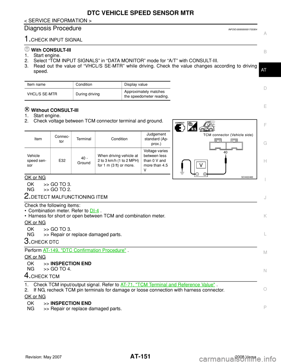
Diagnosis ProcedureINFOID:0000000001703304
1.CHECK INPUT SIGNAL
With CONSULT-III
1. Start engine.
2. Select “TCM INPUT SIGNALS” in “DATA MONITOR” mode for “A/T” with CONSULT-III.
3. Read out the value of “VHCL/S SE-MTR” while driving. Check the value changes according to driving
speed.
Without CONSULT-III
1. Start engine.
2. Check voltage between TCM connector terminal and ground.
OK or NG
OK >> GO TO 3.
NG >> GO TO 2.
2.DETECT MALFUNCTIONING ITEM
Check the following items:
• Combination meter. Refer to DI-4
.
• Harness for short or open between TCM and combination meter.
OK or NG
OK >> GO TO 3.
NG >> Repair or replace damaged parts.
3.CHECK DTC
Perform AT-149, "
DTC Confirmation Procedure" .
OK or NG
OK >>INSPECTION END
NG >> GO TO 4.
4.CHECK TCM
1. Check TCM input/output signal. Refer to AT-71, "
TCM Terminal and Reference Value" .
2. If NG, recheck TCM pin terminals for damage or loose connection with harness connector.
OK or NG
OK >>INSPECTION END
NG >> Repair or replace damaged parts.
Item name Condition Display value
VHCL/S SE-MTR During drivingApproximately matches
the speedometer reading.
Item Connec-
torTerminal ConditionJudgement
standard (Ap-
prox.)
Vehicle
speed sen-
sor E32 40 -
GroundWhen driving vehicle at
2 to 3 km/h (1 to 2 MPH)
for 1 m (3 ft) or more.Voltage varies
between less
than 0 V and
more than 4.5
V
SCIA3246E
Page 242 of 2771
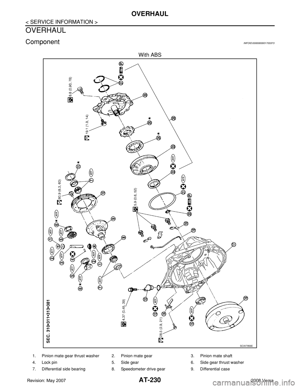
AT-230
< SERVICE INFORMATION >
OVERHAUL
OVERHAUL
ComponentINFOID:0000000001703373
With ABS
SCIA7956E
1. Pinion mate gear thrust washer 2. Pinion mate gear 3. Pinion mate shaft
4. Lock pin 5. Side gear 6. Side gear thrust washer
7. Differential side bearing 8. Speedometer drive gear 9. Differential case
Page 244 of 2771
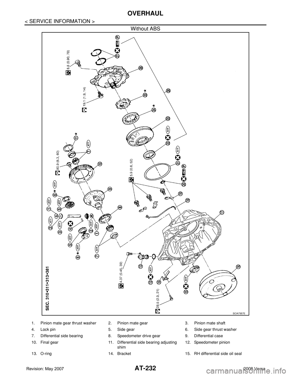
AT-232
< SERVICE INFORMATION >
OVERHAUL
Without ABS
SCIA7957E
1. Pinion mate gear thrust washer 2. Pinion mate gear 3. Pinion mate shaft
4. Lock pin 5. Side gear 6. Side gear thrust washer
7. Differential side bearing 8. Speedometer drive gear 9. Differential case
10. Final gear 11. Differential side bearing adjusting
shim12. Speedometer pinion
13. O-ring 14. Bracket 15. RH differential side oil seal
Page 253 of 2771
DISASSEMBLY
AT-241
< SERVICE INFORMATION >
D
E
F
G
H
I
J
K
L
MA
B
AT
N
O
P
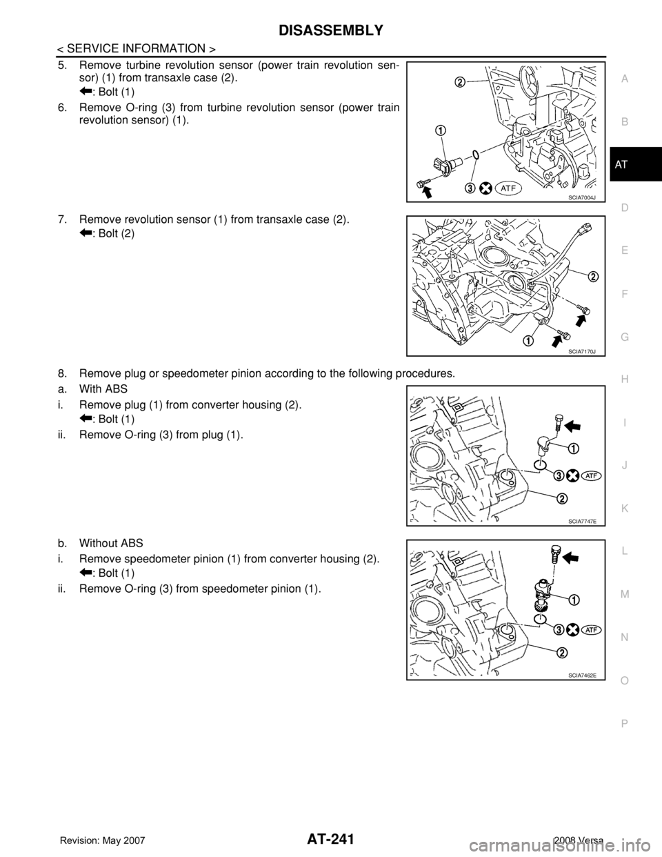
5. Remove turbine revolution sensor (power train revolution sen-
sor) (1) from transaxle case (2).
: Bolt (1)
6. Remove O-ring (3) from turbine revolution sensor (power train
revolution sensor) (1).
7. Remove revolution sensor (1) from transaxle case (2).
: Bolt (2)
8. Remove plug or speedometer pinion according to the following procedures.
a. With ABS
i. Remove plug (1) from converter housing (2).
: Bolt (1)
ii. Remove O-ring (3) from plug (1).
b. Without ABS
i. Remove speedometer pinion (1) from converter housing (2).
: Bolt (1)
ii. Remove O-ring (3) from speedometer pinion (1).
SCIA7004J
SCIA7170J
SCIA7747E
SCIA7462E
Page 325 of 2771
REPAIR FOR COMPONENT PARTS
AT-313
< SERVICE INFORMATION >
D
E
F
G
H
I
J
K
L
MA
B
AT
N
O
P
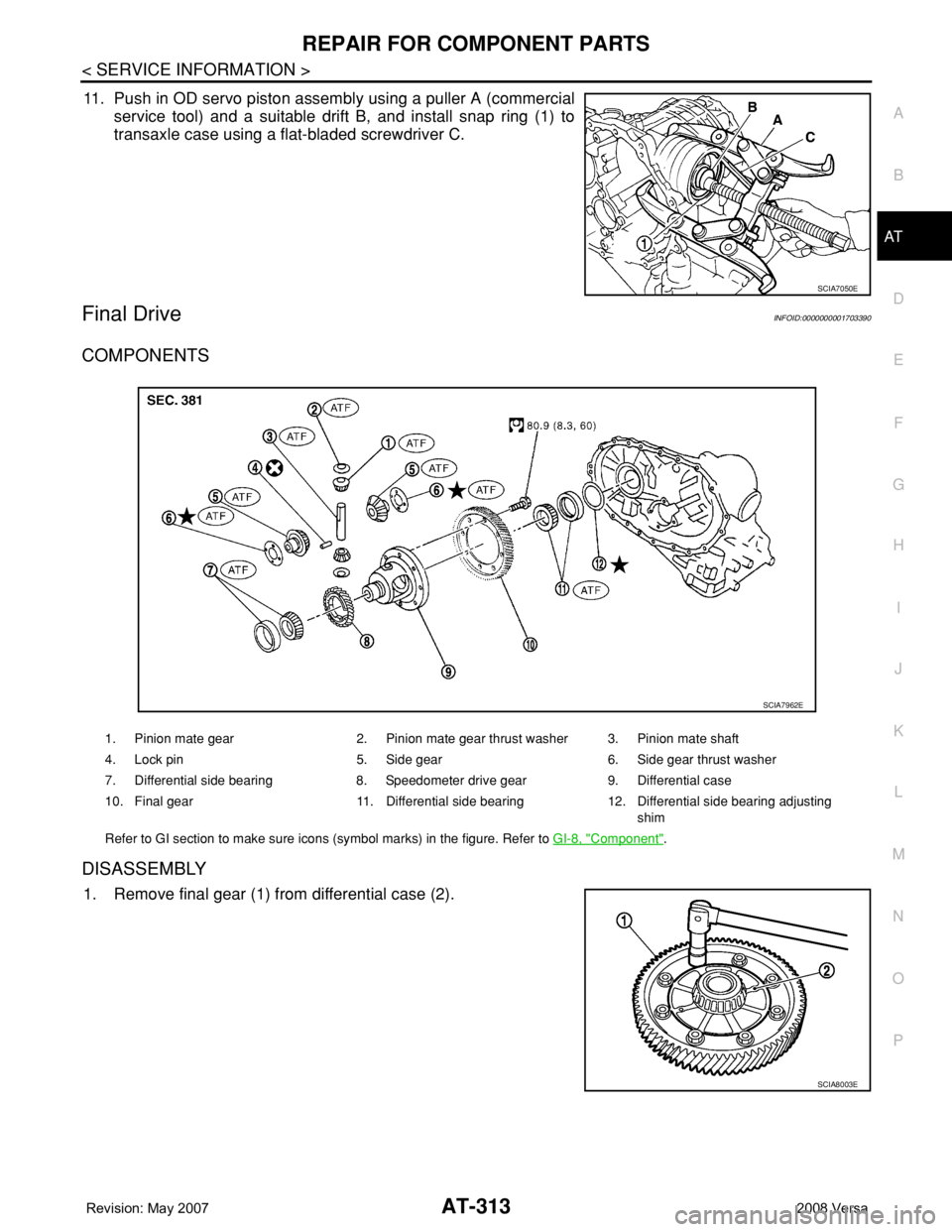
11. Push in OD servo piston assembly using a puller A (commercial
service tool) and a suitable drift B, and install snap ring (1) to
transaxle case using a flat-bladed screwdriver C.
Final DriveINFOID:0000000001703390
COMPONENTS
DISASSEMBLY
1. Remove final gear (1) from differential case (2).
SCIA7050E
1. Pinion mate gear 2. Pinion mate gear thrust washer 3. Pinion mate shaft
4. Lock pin 5. Side gear 6. Side gear thrust washer
7. Differential side bearing 8. Speedometer drive gear 9. Differential case
10. Final gear 11. Differential side bearing 12. Differential side bearing adjusting
shim
Refer to GI section to make sure icons (symbol marks) in the figure. Refer to GI-8, "
Component".
SCIA7962E
SCIA8003E
Page 326 of 2771
AT-314
< SERVICE INFORMATION >
REPAIR FOR COMPONENT PARTS
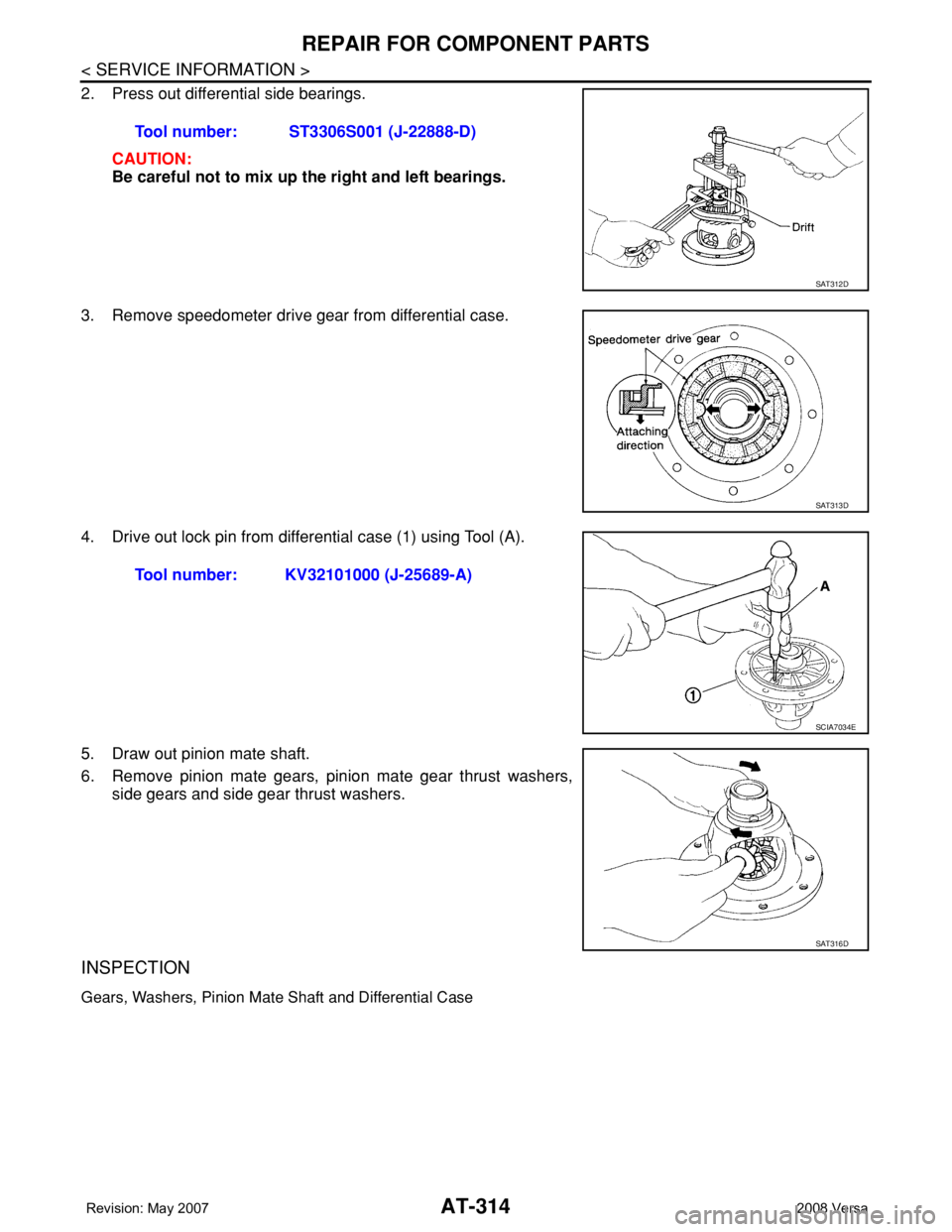
2. Press out differential side bearings.
CAUTION:
Be careful not to mix up the right and left bearings.
3. Remove speedometer drive gear from differential case.
4. Drive out lock pin from differential case (1) using Tool (A).
5. Draw out pinion mate shaft.
6. Remove pinion mate gears, pinion mate gear thrust washers,
side gears and side gear thrust washers.
INSPECTION
Gears, Washers, Pinion Mate Shaft and Differential Case
Tool number: ST3306S001 (J-22888-D)
SAT312D
SAT313D
Tool number: KV32101000 (J-25689-A)
SCIA7034E
SAT316D