steering rack NISSAN TIIDA 2008 Service Repair Manual
[x] Cancel search | Manufacturer: NISSAN, Model Year: 2008, Model line: TIIDA, Model: NISSAN TIIDA 2008Pages: 2771, PDF Size: 60.61 MB
Page 226 of 2771
AT-214
< SERVICE INFORMATION >
KEY INTERLOCK CABLE
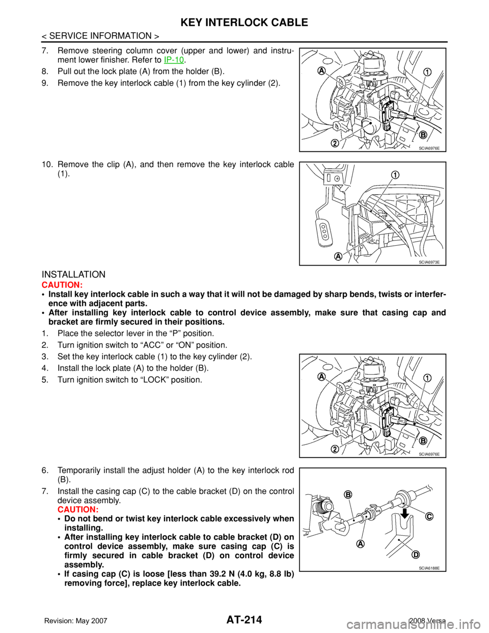
7. Remove steering column cover (upper and lower) and instru-
ment lower finisher. Refer to IP-10
.
8. Pull out the lock plate (A) from the holder (B).
9. Remove the key interlock cable (1) from the key cylinder (2).
10. Remove the clip (A), and then remove the key interlock cable
(1).
INSTALLATION
CAUTION:
• Install key interlock cable in such a way that it will not be damaged by sharp bends, twists or interfer-
ence with adjacent parts.
• After installing key interlock cable to control device assembly, make sure that casing cap and
bracket are firmly secured in their positions.
1. Place the selector lever in the “P” position.
2. Turn ignition switch to “ACC” or “ON” position.
3. Set the key interlock cable (1) to the key cylinder (2).
4. Install the lock plate (A) to the holder (B).
5. Turn ignition switch to “LOCK” position.
6. Temporarily install the adjust holder (A) to the key interlock rod
(B).
7. Install the casing cap (C) to the cable bracket (D) on the control
device assembly.
CAUTION:
• Do not bend or twist key interlock cable excessively when
installing.
• After installing key interlock cable to cable bracket (D) on
control device assembly, make sure casing cap (C) is
firmly secured in cable bracket (D) on control device
assembly.
• If casing cap (C) is loose [less than 39.2 N (4.0 kg, 8.8 lb)
removing force], replace key interlock cable.
SCIA6976E
SCIA6973E
SCIA6976E
SCIA6188E
Page 1013 of 2771
CVT-174
< SERVICE INFORMATION >
KEY INTERLOCK CABLE
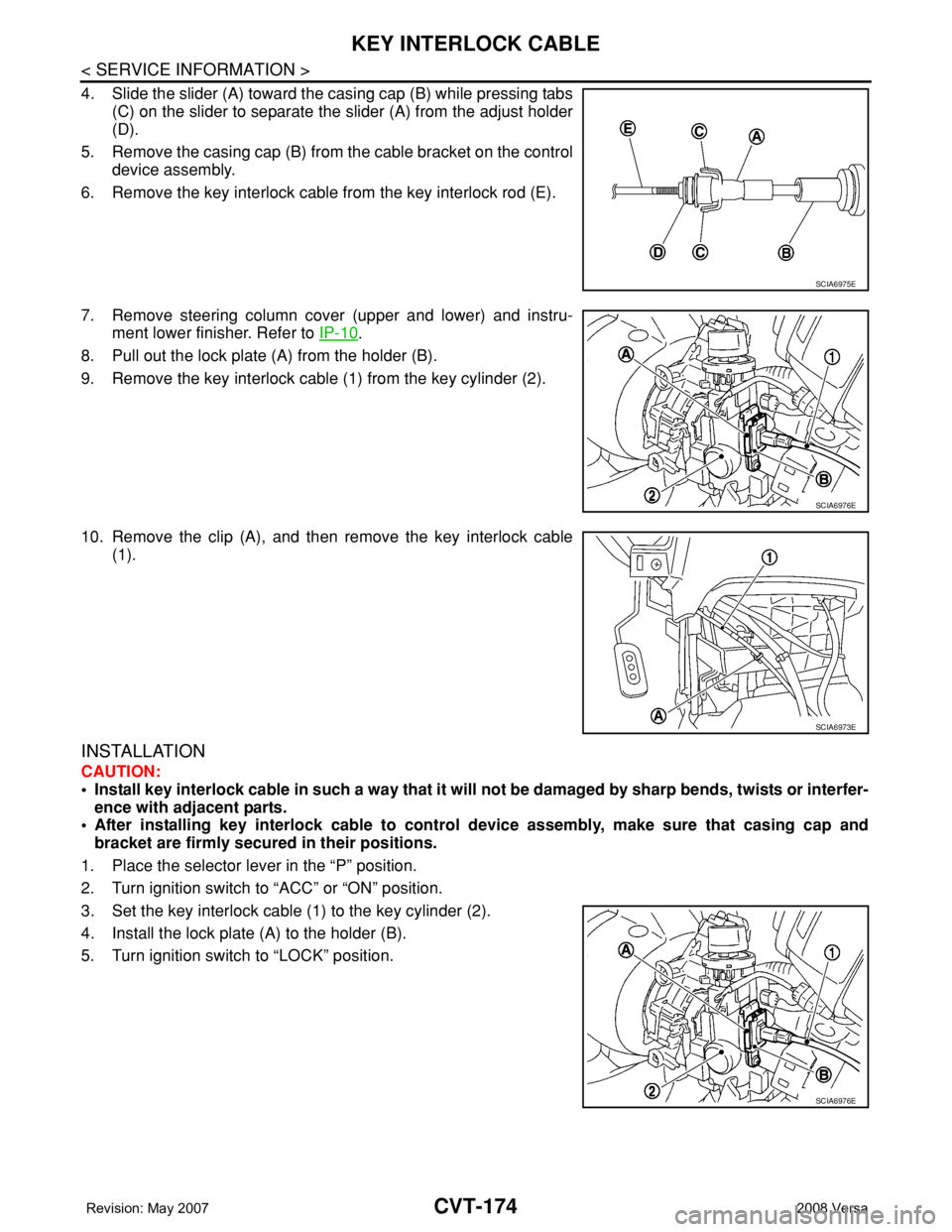
4. Slide the slider (A) toward the casing cap (B) while pressing tabs
(C) on the slider to separate the slider (A) from the adjust holder
(D).
5. Remove the casing cap (B) from the cable bracket on the control
device assembly.
6. Remove the key interlock cable from the key interlock rod (E).
7. Remove steering column cover (upper and lower) and instru-
ment lower finisher. Refer to IP-10
.
8. Pull out the lock plate (A) from the holder (B).
9. Remove the key interlock cable (1) from the key cylinder (2).
10. Remove the clip (A), and then remove the key interlock cable
(1).
INSTALLATION
CAUTION:
• Install key interlock cable in such a way that it will not be damaged by sharp bends, twists or interfer-
ence with adjacent parts.
• After installing key interlock cable to control device assembly, make sure that casing cap and
bracket are firmly secured in their positions.
1. Place the selector lever in the “P” position.
2. Turn ignition switch to “ACC” or “ON” position.
3. Set the key interlock cable (1) to the key cylinder (2).
4. Install the lock plate (A) to the holder (B).
5. Turn ignition switch to “LOCK” position.
SCIA6975E
SCIA6976E
SCIA6973E
SCIA6976E
Page 1014 of 2771
KEY INTERLOCK CABLE
CVT-175
< SERVICE INFORMATION >
D
E
F
G
H
I
J
K
L
MA
B
CVT
N
O
P
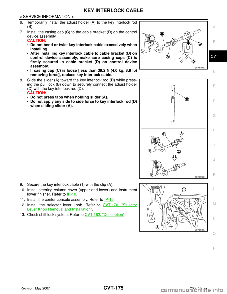
6. Temporarily install the adjust holder (A) to the key interlock rod
(B).
7. Install the casing cap (C) to the cable bracket (D) on the control
device assembly.
CAUTION:
• Do not bend or twist key interlock cable excessively when
installing.
• After installing key interlock cable to cable bracket (D) on
control device assembly, make sure casing caps (C) is
firmly secured in cable bracket (D) on control device
assembly.
• If casing cap (C) is loose [less than 39.2 N (4.0 kg, 8.8 lb)
removing force], replace key interlock cable.
8. Slide the slider (A) toward the key interlock rod (D) while press-
ing the pull lock (B) down to securely connect the adjust holder
(C) with the key interlock rod (D).
CAUTION:
• Do not press tabs when holding slider (A).
• Do not apply any side to side force to key interlock rod (D)
when sliding slider (A).
9. Secure the key interlock cable (1) with the clip (A).
10. Install steering column cover (upper and lower) and instrument
lower finisher. Refer to IP-10
.
11. Install the center console assembly. Refer to IP-10
.
12. Install the selector lever knob. Refer to CVT-170, "
Selector
Lever Knob Removal and Installation".
13. Check shift lock system. Refer to CVT-162, "
Description".
SCIA6188E
SCIA6978E
SCIA6973E
Page 1666 of 2771
FLOOR TRIM
EI-43
< ON-VEHICLE REPAIR >
C
D
E
F
G
H
J
K
L
MA
B
EI
N
O
P
FLOOR TRIM
Removal and InstallationINFOID:0000000001704238
REMOVAL
1. Disconnect both the negative and positive battery cables, then wait at least 3 minutes.
2. Remove front seat assembly RH/LH and rear seat cushion. Refer to SE-11, "
Removal and Installation"
and SE-15, "Removal and Installation".
3. Remove center console and floor bracket. Refer to IP-11, "
Removal and Installation".
4. Remove instrument lower cover. Refer to IP-11, "
Removal and Installation".
5. Remove front kicking plate inner RH/LH, center pillar lower garnish RH/LH, and rear kicking plate inner
RH/LH. Refer to EI-38, "
Removal and Installation".
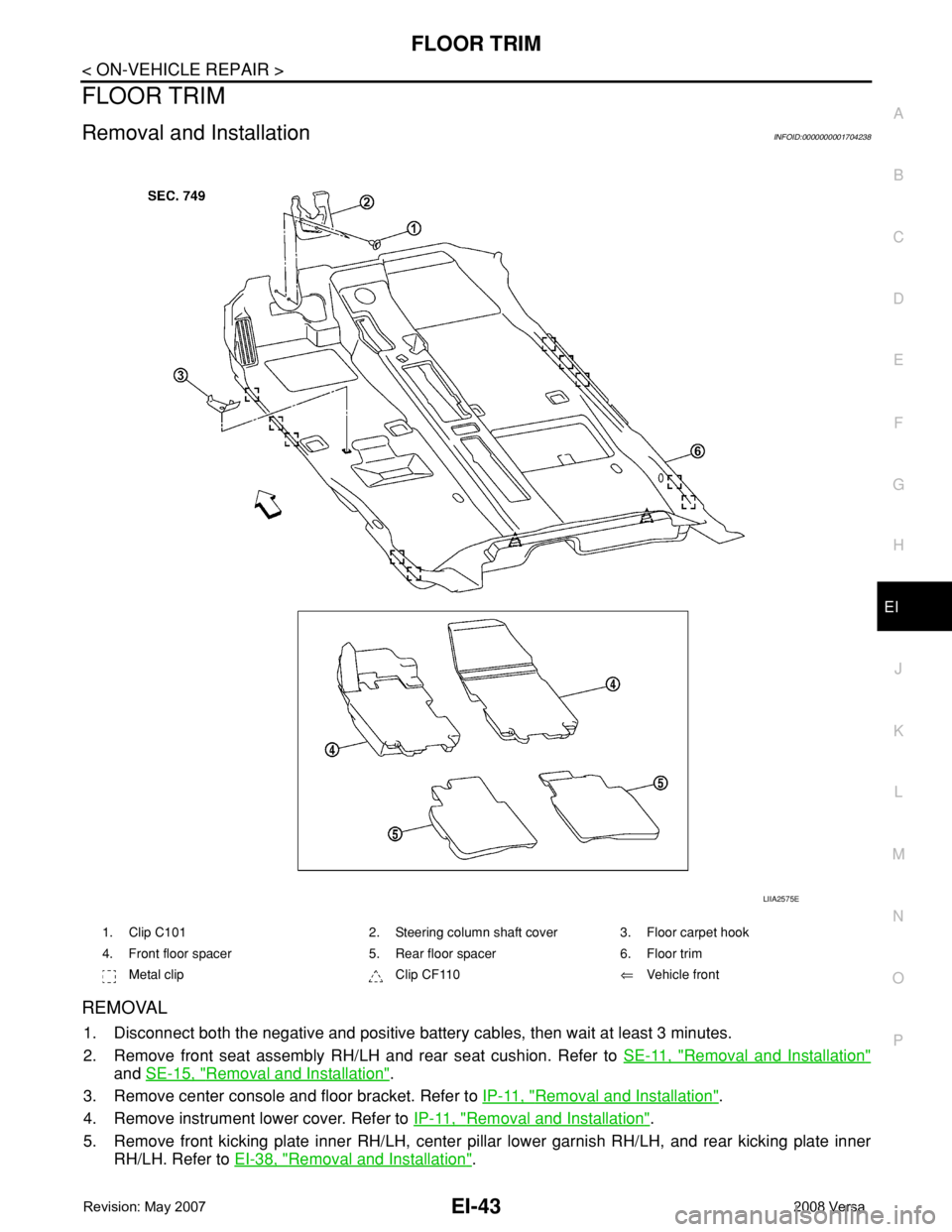
1. Clip C101 2. Steering column shaft cover 3. Floor carpet hook
4. Front floor spacer 5. Rear floor spacer 6. Floor trim
Metal clip Clip CF110⇐Vehicle front
LIIA2575E
Page 1803 of 2771
FRONT WHEEL HUB AND KNUCKLE
FAX-7
< SERVICE INFORMATION >
C
E
F
G
H
I
J
K
L
MA
B
FA X
N
O
P
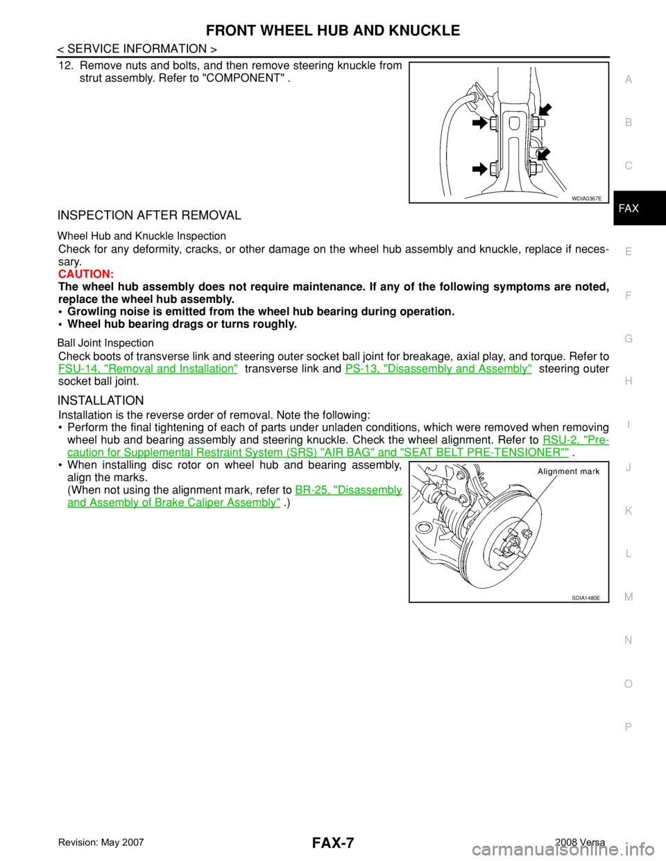
12. Remove nuts and bolts, and then remove steering knuckle from
strut assembly. Refer to "COMPONENT" .
INSPECTION AFTER REMOVAL
Wheel Hub and Knuckle Inspection
Check for any deformity, cracks, or other damage on the wheel hub assembly and knuckle, replace if neces-
sary.
CAUTION:
The wheel hub assembly does not require maintenance. If any of the following symptoms are noted,
replace the wheel hub assembly.
• Growling noise is emitted from the wheel hub bearing during operation.
• Wheel hub bearing drags or turns roughly.
Ball Joint Inspection
Check boots of transverse link and steering outer socket ball joint for breakage, axial play, and torque. Refer to
FSU-14, "
Removal and Installation" transverse link and PS-13, "Disassembly and Assembly" steering outer
socket ball joint.
INSTALLATION
Installation is the reverse order of removal. Note the following:
• Perform the final tightening of each of parts under unladen conditions, which were removed when removing
wheel hub and bearing assembly and steering knuckle. Check the wheel alignment. Refer to RSU-2, "
Pre-
caution for Supplemental Restraint System (SRS) "AIR BAG" and "SEAT BELT PRE-TENSIONER"" .
• When installing disc rotor on wheel hub and bearing assembly,
align the marks.
(When not using the alignment mark, refer to BR-25, "
Disassembly
and Assembly of Brake Caliper Assembly" .)
WDIA0367E
SDIA1480E
Page 1804 of 2771
FAX-8
< SERVICE INFORMATION >
FRONT DRIVE SHAFT
FRONT DRIVE SHAFT
On-Vehicle Inspection and ServiceINFOID:0000000001703703
• Check drive shaft mounting point and joint for looseness and other damage.
• Check boot for cracks and other damage.
Replace or repair components as necessary. Refer to FA X - 8 , "
Removal and Installation (Left Side)" , FA X - 9 ,
"Removal and Installation (Right Side)" , FAX-12, "Disassembly and Assembly (Left Side)" or FAX-17, "Disas-
sembly and Assembly (Right Side)" .
CAUTION:
Replace entire drive shaft assembly when noise or vibration occur from drive shaft.
Removal and Installation (Left Side)INFOID:0000000001703704
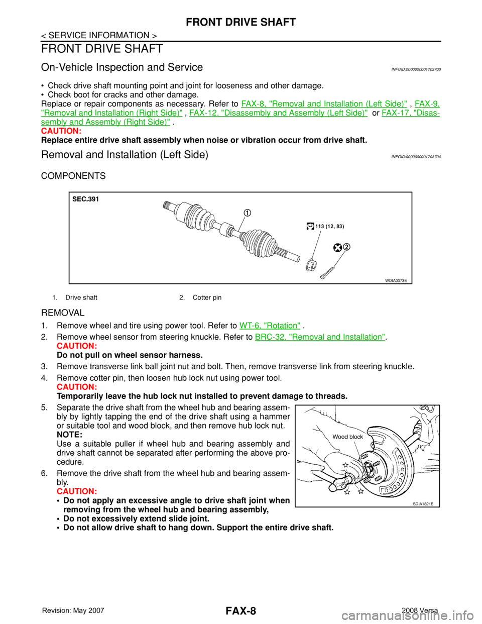
COMPONENTS
REMOVAL
1. Remove wheel and tire using power tool. Refer to WT-6, "Rotation" .
2. Remove wheel sensor from steering knuckle. Refer to BRC-32, "
Removal and Installation".
CAUTION:
Do not pull on wheel sensor harness.
3. Remove transverse link ball joint nut and bolt. Then, remove transverse link from steering knuckle.
4. Remove cotter pin, then loosen hub lock nut using power tool.
CAUTION:
Temporarily leave the hub lock nut installed to prevent damage to threads.
5. Separate the drive shaft from the wheel hub and bearing assem-
bly by lightly tapping the end of the drive shaft using a hammer
or suitable tool and wood block, and then remove hub lock nut.
NOTE:
Use a suitable puller if wheel hub and bearing assembly and
drive shaft cannot be separated after performing the above pro-
cedure.
6. Remove the drive shaft from the wheel hub and bearing assem-
bly.
CAUTION:
• Do not apply an excessive angle to drive shaft joint when
removing from the wheel hub and bearing assembly,
• Do not excessively extend slide joint.
• Do not allow drive shaft to hang down. Support the entire drive shaft.
1. Drive shaft 2. Cotter pin
WDIA0373E
SDIA1821E
Page 1806 of 2771
FAX-10
< SERVICE INFORMATION >
FRONT DRIVE SHAFT
REMOVAL
1. Remove wheel and tire using power tool. Refer to WT-6, "Rotation" .
2. Remove wheel sensor from steering knuckle. Refer to BRC-32, "
Removal and Installation".
CAUTION:
Do not pull on wheel sensor harness.
3. Remove transverse link ball joint nut and bolt. Then, remove transverse link from steering knuckle.
4. Remove cotter pin, then loosen hub lock nut using power tool.
CAUTION:
Temporarily leave the hub lock nut installed to prevent damage to threads.
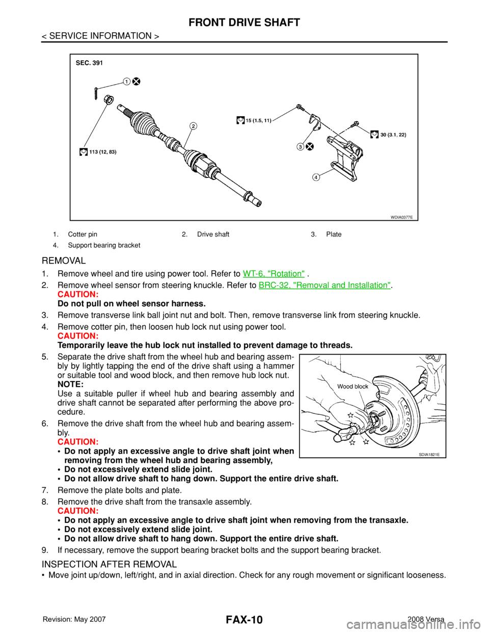
5. Separate the drive shaft from the wheel hub and bearing assem-
bly by lightly tapping the end of the drive shaft using a hammer
or suitable tool and wood block, and then remove hub lock nut.
NOTE:
Use a suitable puller if wheel hub and bearing assembly and
drive shaft cannot be separated after performing the above pro-
cedure.
6. Remove the drive shaft from the wheel hub and bearing assem-
bly.
CAUTION:
• Do not apply an excessive angle to drive shaft joint when
removing from the wheel hub and bearing assembly,
• Do not excessively extend slide joint.
• Do not allow drive shaft to hang down. Support the entire drive shaft.
7. Remove the plate bolts and plate.
8. Remove the drive shaft from the transaxle assembly.
CAUTION:
• Do not apply an excessive angle to drive shaft joint when removing from the transaxle.
• Do not excessively extend slide joint.
• Do not allow drive shaft to hang down. Support the entire drive shaft.
9. If necessary, remove the support bearing bracket bolts and the support bearing bracket.
INSPECTION AFTER REMOVAL
• Move joint up/down, left/right, and in axial direction. Check for any rough movement or significant looseness.
1. Cotter pin 2. Drive shaft 3. Plate
4. Support bearing bracket
WDIA0377E
SDIA1821E
Page 1848 of 2771
FSU-14
< SERVICE INFORMATION >
TRANSVERSE LINK
TRANSVERSE LINK
Removal and InstallationINFOID:0000000001703727
REMOVAL
1. Remove front tires using power tool.
2. Remove transverse link ball joint nut and bolt. Then, remove transverse link from steering knuckle.
3. Remove transverse link nuts and bolts, then remove transverse
link from front suspension member.
NOTE:
When removing LH transverse link it may be necessay to lower
the suspension member in order to remove bolts to avoid con-
tact with the transaxle.
a. Set jack under front suspension member.
b. Loosen RH upper link bolts, LH upper link bolt (front suspension
member side), front suspension member bolts (left/right). Lower
the front suspension member in order to remove transverse link
bolts.
4. Remove transverse link.
INSPECTION AFTER REMOVAL
Visual Inspection
Check the following:
• Transverse link and bushing for deformation, cracks or damage. Replace it if necessary.
• Ball joint boot for cracks or other damage, and also for grease leakage. Replace it if necessary.
Ball Joint Inspection
Manually move ball stud to confirm it moves smoothly with no binding.
Swing Torque Inspection
NOTE:
Before measurement, move ball stud at least ten times by hand to check for smooth movement.
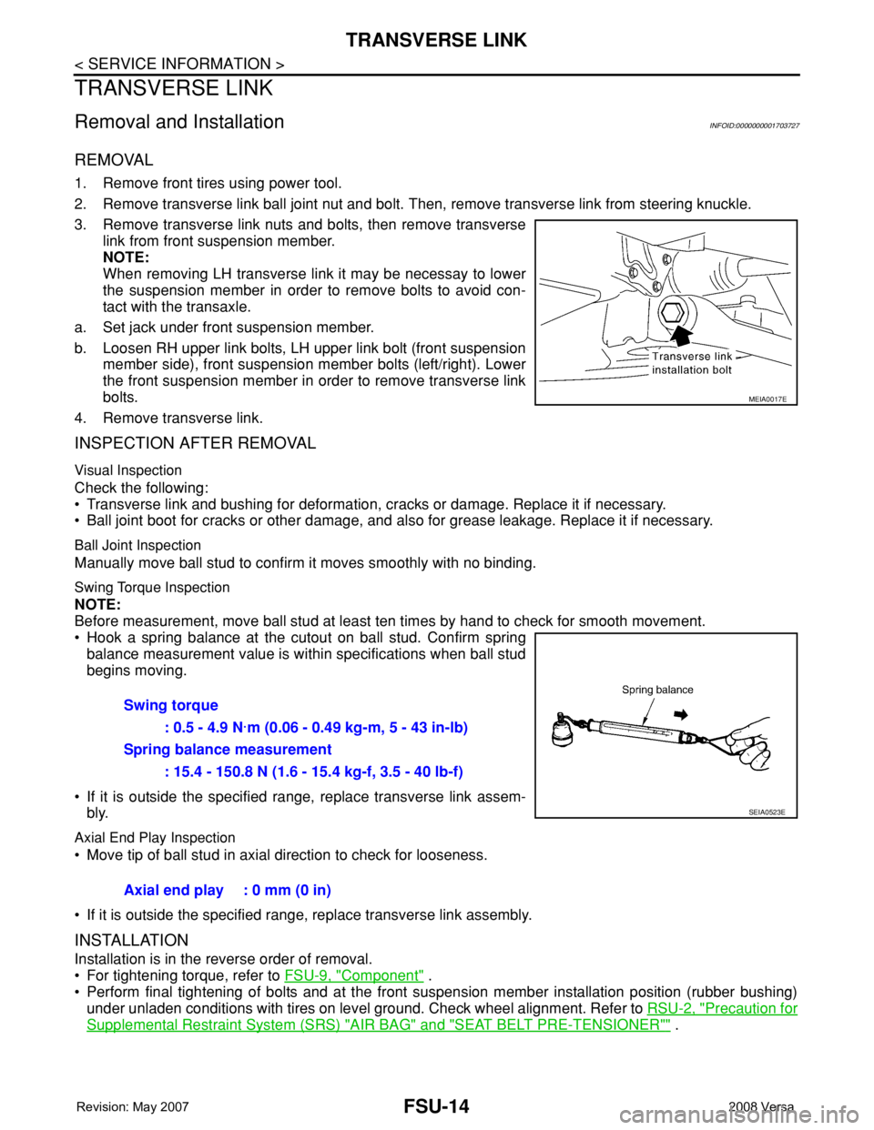
• Hook a spring balance at the cutout on ball stud. Confirm spring
balance measurement value is within specifications when ball stud
begins moving.
• If it is outside the specified range, replace transverse link assem-
bly.
Axial End Play Inspection
• Move tip of ball stud in axial direction to check for looseness.
• If it is outside the specified range, replace transverse link assembly.
INSTALLATION
Installation is in the reverse order of removal.
• For tightening torque, refer to FSU-9, "
Component" .
• Perform final tightening of bolts and at the front suspension member installation position (rubber bushing)
under unladen conditions with tires on level ground. Check wheel alignment. Refer to RSU-2, "
Precaution for
Supplemental Restraint System (SRS) "AIR BAG" and "SEAT BELT PRE-TENSIONER"" .
MEIA0017E
Swing torque
: 0.5 - 4.9 N·m (0.06 - 0.49 kg-m, 5 - 43 in-lb)
Spring balance measurement
: 15.4 - 150.8 N (1.6 - 15.4 kg-f, 3.5 - 40 lb-f)
SEIA0523E
Axial end play : 0 mm (0 in)
Page 1849 of 2771
STABILIZER BAR
FSU-15
< SERVICE INFORMATION >
C
D
F
G
H
I
J
K
L
MA
B
FSU
N
O
P
STABILIZER BAR
Removal and InstallationINFOID:0000000001703728
REMOVAL
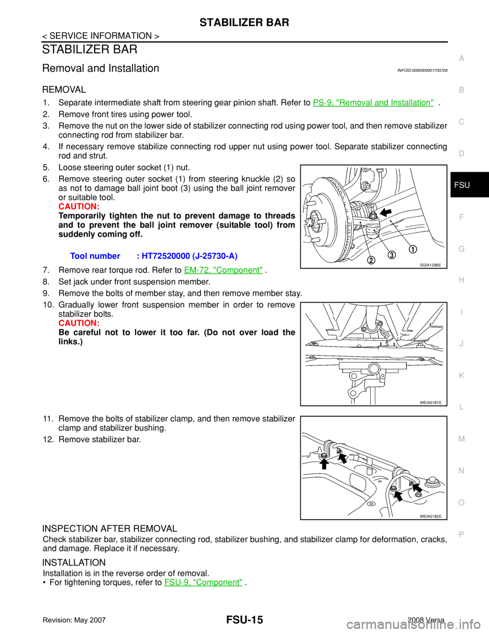
1. Separate intermediate shaft from steering gear pinion shaft. Refer to PS-9, "Removal and Installation" .
2. Remove front tires using power tool.
3. Remove the nut on the lower side of stabilizer connecting rod using power tool, and then remove stabilizer
connecting rod from stabilizer bar.
4. If necessary remove stabilize connecting rod upper nut using power tool. Separate stabilizer connecting
rod and strut.
5. Loose steering outer socket (1) nut.
6. Remove steering outer socket (1) from steering knuckle (2) so
as not to damage ball joint boot (3) using the ball joint remover
or suitable tool.
CAUTION:
Temporarily tighten the nut to prevent damage to threads
and to prevent the ball joint remover (suitable tool) from
suddenly coming off.
7. Remove rear torque rod. Refer to EM-72, "
Component" .
8. Set jack under front suspension member.
9. Remove the bolts of member stay, and then remove member stay.
10. Gradually lower front suspension member in order to remove
stabilizer bolts.
CAUTION:
Be careful not to lower it too far. (Do not over load the
links.)
11. Remove the bolts of stabilizer clamp, and then remove stabilizer
clamp and stabilizer bushing.
12. Remove stabilizer bar.
INSPECTION AFTER REMOVAL
Check stabilizer bar, stabilizer connecting rod, stabilizer bushing, and stabilizer clamp for deformation, cracks,
and damage. Replace it if necessary.
INSTALLATION
Installation is in the reverse order of removal.
• For tightening torques, refer to FSU-9, "
Component" . Tool number : HT72520000 (J-25730-A)
SGIA1298E
WEIA0181E
WEIA0182E
Page 2264 of 2771
MA-4
< SERVICE INFORMATION >
GENERAL MAINTENANCE
GENERAL MAINTENANCE
Explanation of General MaintenanceINFOID:0000000001704720
General MaintenanceINFOID:0000000001704721
General maintenance includes those items which should be checked during the normal day-to-day operation
of the vehicle. They are essential if the vehicle is to continue operating properly. The owners can perform
checks and inspections themselves or they can have their NISSAN dealers do them.
OUTSIDE THE VEHICLE
The maintenance items listed here should be performed from time to time, unless otherwise specified.
INSIDE THE VEHICLE
The maintenance items listed here should be checked on a regular basis, such as when performing periodic maintenance, cleaning the vehicle,
etc.
ItemReference page
TiresCheck the pressure including the spare, at least once a month and always prior
to a long distance trip. Adjust to the specified pressure if necessary. Check care-
fully for damage, cuts or excessive wear.WT-25, "
Tire"
Wheel nutsWhen checking the tires, make sure no nuts are missing, and check for any loose
nuts. Tighten if necessary.WT-6, "Rotation"
WindshieldClean the windshield on a regular basis. Check the windshield at least every six
months for cracks or other damage. Repair as necessary.—
Tire rotationTires should be rotated every 12,000 km (7,500 miles).WT-6, "
Rotation"
Transmitter compo-
nents in tire pressure
monitoring systemReplace grommet seal, valve core and cap of the transmitter in TPMS every tire
replacement by reaching wear limit of tire.WT-7
Wheel alignment and
balanceIf the vehicle pulls to either side while driving on a straight and level road, or if
you detect uneven or abnormal tire wear, there may be a need for wheel align-
ment. If the steering wheel or seat vibrates at normal highway speeds, wheel bal-
ancing may be needed.FSU-6, "Wheel Align-
ment Inspection" and
WT-6, "
Balancing
Wheels"
Windshield wiper
bladesCheck for cracks or wear if they do not wipe properly. —
Doors and engine
hoodCheck that all doors and the engine hood operate smoothly as well as the trunk
lid and back hatch. Also make sure that all latches lock securely. Lubricate if nec-
essary. Make sure that the secondary latch keeps the hood from opening when
the primary latch is released.
When driving in areas using road salt or other corrosive materials, check lubrica-
tion frequently.MA-27, "
Lubricating
Locks, Hinges and Hood
Latch"
LampsMake sure that the headlamps, stop lamps, tail lamps, turn signal lamps, and oth-
er lamps are all operating properly and installed securely. Also check headlamp
aim. Clean the headlamps on a regular basis.—
ItemReference page
Warning lamps and
buzzers/chimesMake sure that all warning lamps and buzzers/chimes are operating properly. —
Windshield wiper and
washerCheck that the wipers and washer operate properly and that the wipers do not
streak.—
Windshield defrosterCheck that the air comes out of the defroster outlets properly and in sufficient
quantity when operating the heater or air conditioning.—
Steering wheelCheck that it has the specified play. Be sure to check for changes in the steering
condition, such as excessive play, hard steering or strange noises.
Free play: Less than 35 mm (1.38 in)—
SeatsCheck seat position controls such as seat adjusters, seat back recliner, etc. to
make sure they operate smoothly and that all latches lock securely in every po-
sition. Check that the head restraints move up and down smoothly and that the
locks (if equipped) hold securely in all latched positions. Check that the latches
lock securely for folding-down rear seat backs.—