transmission input sensor NISSAN TIIDA 2008 Service Repair Manual
[x] Cancel search | Manufacturer: NISSAN, Model Year: 2008, Model line: TIIDA, Model: NISSAN TIIDA 2008Pages: 2771, PDF Size: 60.61 MB
Page 40 of 2771
AT-28
< SERVICE INFORMATION >
A/T CONTROL SYSTEM
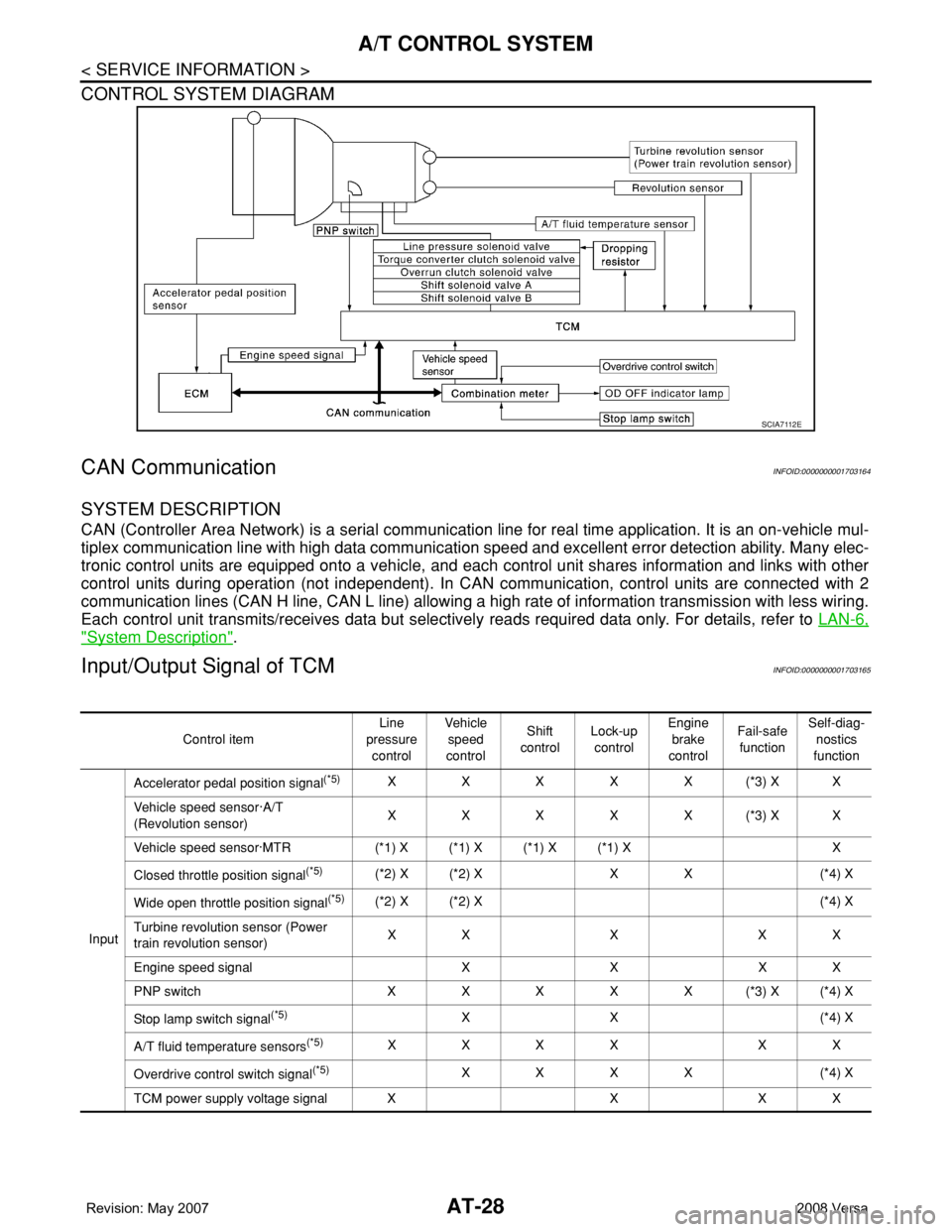
CONTROL SYSTEM DIAGRAM
CAN CommunicationINFOID:0000000001703164
SYSTEM DESCRIPTION
CAN (Controller Area Network) is a serial communication line for real time application. It is an on-vehicle mul-
tiplex communication line with high data communication speed and excellent error detection ability. Many elec-
tronic control units are equipped onto a vehicle, and each control unit shares information and links with other
control units during operation (not independent). In CAN communication, control units are connected with 2
communication lines (CAN H line, CAN L line) allowing a high rate of information transmission with less wiring.
Each control unit transmits/receives data but selectively reads required data only. For details, refer to LAN-6,
"System Description".
Input/Output Signal of TCMINFOID:0000000001703165
SCIA7112E
Control itemLine
pressure
controlVehicle
speed
controlShift
controlLock-up
controlEngine
brake
controlFail-safe
functionSelf-diag-
nostics
function
InputAccelerator pedal position signal
(*5)XXXXX(*3) XX
Vehicle speed sensor·A/T
(Revolution sensor)XXXXX(*3) XX
Vehicle speed sensor·MTR (*1) X (*1) X (*1) X (*1) X X
Closed throttle position signal
(*5)(*2) X (*2) X X X (*4) X
Wide open throttle position signal
(*5)(*2) X (*2) X (*4) X
Turbine revolution sensor (Power
train revolution sensor)XXXXX
Engine speed signal X X X X
PNP switch XXXXX(*3) X(*4) X
Stop lamp switch signal
(*5)XX (*4) X
A/T fluid temperature sensors
(*5)XXXX XX
Overdrive control switch signal
(*5)XXXX (*4) X
TCM power supply voltage signal X X X X
Page 868 of 2771

TROUBLE DIAGNOSIS
CVT-29
< SERVICE INFORMATION >
D
E
F
G
H
I
J
K
L
MA
B
CVT
N
O
P
TROUBLE DIAGNOSIS
DTC Inspection Priority ChartINFOID:0000000001703451
If some DTCs are displayed at the same time, perform inspections one by one based on the following priority
chart.
NOTE:
If DTC “U1000 CAN COMM CIRCUIT” is displayed with other DTCs, first perform the trouble diagnosis
for “DTC U1000 CAN COMMUNICATION LINE”. Refer to CVT-56
.
Fail-SafeINFOID:0000000001703452
The TCM has an electrical fail-safe mode. This mode makes it possible to operate even if there is an error in a
main electronic control input/output signal circuit.
FAIL-SAFE FUNCTION
If any malfunction occurs in a sensor or solenoid, this function controls the CVT to make driving possible.
Output Speed Sensor (Secondary Speed Sensor)
The shift pattern is changed in accordance with throttle position when an unexpected signal is sent from the
output speed sensor (secondary speed sensor) to the TCM. The overdrive-off mode is inhibited, and the tran-
saxle is put in “D”.
Input Speed Sensor (Primary Speed Sensor)
The shift pattern is changed in accordance with throttle position and secondary speed (vehicle speed) when
an unexpected signal is sent from the input speed sensor (primary speed sensor) to the TCM. The sport mode
is inhibited, and the transaxle is put in “D”.
PNP Switch
If an unexpected signal is sent from the PNP switch to the TCM, the transaxle is put in “D”.
CVT Fluid Temperature Sensor
If an unexpected signal is sent from the CVT fluid temperature sensor to the TCM, the gear ratio in use before
receiving the unexpected signal is maintained or the gear ratio is controlled to keep engine speed under 3500
rpm.
Transmission Fluid Pressure Sensor A (Secondary Pressure Sensor)
• If an unexpected signal is sent from the transmission fluid pressure sensor A (secondary pressure sensor) to
the TCM, the secondary pressure feedback control is stopped and the offset value obtained before the non-
standard condition occurs is used to control line pressure.
• If transmission fluid pressure sensor A (secondary pressure sensor) error signal is input to TCM, secondary
pressure feedback control stops, but line pressure is controlled normally.
Pressure Control Solenoid A (Line Pressure Solenoid)
If an unexpected signal is sent from the solenoid to the TCM, the pressure control solenoid A (line pressure
solenoid) is turned OFF to achieve the maximum fluid pressure.
Pressure Control Solenoid B (Secondary Pressure Solenoid)
If an unexpected signal is sent from the solenoid to the TCM, the pressure control solenoid B (secondary pres-
sure solenoid) is turned OFF to achieve the maximum fluid pressure.
Torque Converter Clutch Solenoid
If an unexpected signal is sent from the solenoid to the TCM, the torque converter clutch solenoid is turned
OFF to cancel the lock-up.
Ste p M oto r
If an unexpected signal is sent from the step motor to the TCM, the step motor coil phases “A” through “D” are
all turned OFF to hold the gear ratio used right before the non-standard condition occurred.
CVT Lock-up Select Solenoid
Priority Detected items (DTC)
1 U1000 CAN communication line
2 Except above
Page 886 of 2771
TROUBLE DIAGNOSIS
CVT-47
< SERVICE INFORMATION >
D
E
F
G
H
I
J
K
L
MA
B
CVT
N
O
P
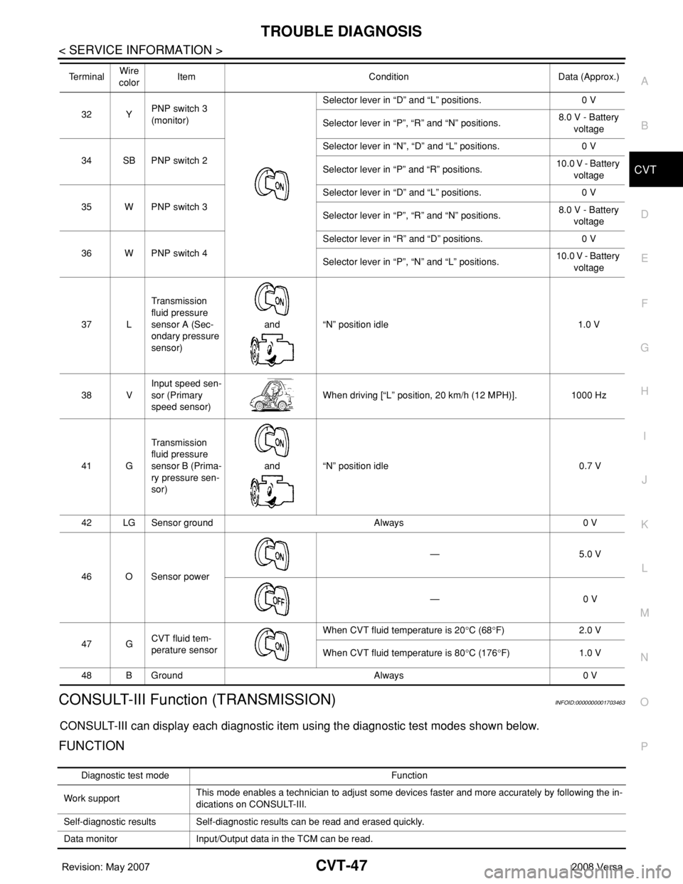
CONSULT-III Function (TRANSMISSION)INFOID:0000000001703463
CONSULT-III can display each diagnostic item using the diagnostic test modes shown below.
FUNCTION
32 YPNP switch 3
(monitor)Selector lever in “D” and “L” positions. 0 V
Selector lever in “P”, “R” and “N” positions.8.0 V - Battery
voltage
34 SB PNP switch 2Selector lever in “N”, “D” and “L” positions. 0 V
Selector lever in “P” and “R” positions.10.0 V - Battery
voltage
35 W PNP switch 3Selector lever in “D” and “L” positions. 0 V
Selector lever in “P”, “R” and “N” positions.8.0 V - Battery
voltage
36 W PNP switch 4Selector lever in “R” and “D” positions. 0 V
Selector lever in “P”, “N” and “L” positions.10.0 V - Battery
voltage
37 LTransmission
fluid pressure
sensor A (Sec-
ondary pressure
sensor)and “N” position idle 1.0 V
38 VInput speed sen-
sor (Primary
speed sensor)When driving [“L” position, 20 km/h (12 MPH)]. 1000 Hz
41 GTransmission
fluid pressure
sensor B (Prima-
ry pressure sen-
sor)and “N” position idle 0.7 V
42 LG Sensor ground Always 0 V
46 O Sensor power— 5.0 V
— 0 V
47 GCVT fluid tem-
perature sensor When CVT fluid temperature is 20°C (68°F) 2.0 V
When CVT fluid temperature is 80°C (176°F) 1.0 V
48 B Ground Always 0 V Te r m i n a lWire
colorItem Condition Data (Approx.)
Diagnostic test mode Function
Work supportThis mode enables a technician to adjust some devices faster and more accurately by following the in-
dications on CONSULT-III.
Self-diagnostic results Self-diagnostic results can be read and erased quickly.
Data monitor Input/Output data in the TCM can be read.
Page 890 of 2771
![NISSAN TIIDA 2008 Service Repair Manual TROUBLE DIAGNOSIS
CVT-51
< SERVICE INFORMATION >
D
E
F
G
H
I
J
K
L
MA
B
CVT
N
O
PVEH SPD SEN/
CIR AT• Signal from vehicle speed sensor CVT [Output speed sen-
sor (Secondary speed sensor)] not input NISSAN TIIDA 2008 Service Repair Manual TROUBLE DIAGNOSIS
CVT-51
< SERVICE INFORMATION >
D
E
F
G
H
I
J
K
L
MA
B
CVT
N
O
PVEH SPD SEN/
CIR AT• Signal from vehicle speed sensor CVT [Output speed sen-
sor (Secondary speed sensor)] not input](/img/5/57399/w960_57399-889.png)
TROUBLE DIAGNOSIS
CVT-51
< SERVICE INFORMATION >
D
E
F
G
H
I
J
K
L
MA
B
CVT
N
O
PVEH SPD SEN/
CIR AT• Signal from vehicle speed sensor CVT [Output speed sen-
sor (Secondary speed sensor)] not input due to open or
short circuit
• Unexpected signal input during runningP0720 P0720CVT-80
ENGINE SPEED
SIG• TCM does not receive the CAN communication signal from
the ECM
• Engine speed is too low while drivingP0725 —CVT-85
BELT DAMG Unexpected gear ratio detected P0730 —CVT-87
TCC SOLENOID/
CIRCNormal voltage not applied to solenoid due to open or short
circuitP0740 P0740CVT-88
A/T TCC S/V
FNCTN• CVT cannot perform lock-up even if electrical circuit is good
• TCM detects as irregular by comparing difference value
with slip rotation
• There is big difference engine speed and primary speed
when TCM lock-up signal is onP0744 P0744CVT-93
L/PRESS SOL/
CIRC• Normal voltage not applied to solenoid due to open or short
circuit
• TCM detects as irregular by comparing target value with
monitor valueP0745 P0745CVT-95
PRS CNT SOL/A
FCTNUnexpected gear ratio was detected in the LOW side due to
excessively low line pressureP0746 P0746CVT-100
PRS CNT SOL/B
FCTNSecondary pressure is too high or too low compared with the
commanded value while drivingP0776 P0776CVT-102
PRS CNT SOL/B
CIRC• Normal voltage not applied to solenoid due to cut line,
short, or the like
• TCM detects as irregular by comparing target value with
monitor valueP0778 P0778CVT-104
TR PRS SENS/A
CIRCSignal voltage of the transmission fluid pressure sensor A
(secondary pressure sensor) is too high or too low while driv-
ingP0840 P0840CVT-109
PRESS SEN/
FNCTNCorrelation between the values of the transmission fluid pres-
sure sensor A (secondary pressure sensor) and the transmis-
sion fluid pressure sensor B (primary pressure sensor) is out
of specificationP0841 —CVT-113
TR PRS SENS/B
CIRCSignal voltage of the transmission fluid pressure sensor B
(primary pressure sensor) is too high or too low while drivingP0845 P0845CVT-115
SEC/PRESS
DOWNSecondary fluid pressure is too low compared with the com-
manded value while drivingP0868 —CVT-119
TCM-POWER
SUPPLY• When the power supply to the TCM is cut OFF, for example
because the battery is removed, and the self-diagnosis
memory function stops
• This is not a malfunction message (Whenever shutting
OFF a power supply to the TCM, this message appears on
the screen)P1701 —CVT-121
TP SEN/CIRC A/TTCM does not receive the proper accelerator pedal position
signals (input by CAN communication) from ECMP1705 —CVT-125
ESTM VEH SPD
SIG*2• CAN communication with the ABS actuator and the electric
unit (control unit) is malfunctioning
• There is a great difference between the vehicle speed sig-
nal from the ABS actuator and the electric unit (control
unit), and the vehicle speed sensor signalP1722 —CVT-127
Items (CONSULT-
III screen terms)Malfunction is detected when...TCM self-di-
agnosisOBD-III (DTC)
Reference
page “TRANSMIS-
SION” with
CONSULT-IIIMIL indicator
lamp*1, “EN-
GINE” with
CONSULT-III
or GST
Page 912 of 2771
DTC P0710 CVT FLUID TEMPERATURE SENSOR CIRCUIT
CVT-73
< SERVICE INFORMATION >
D
E
F
G
H
I
J
K
L
MA
B
CVT
N
O
P
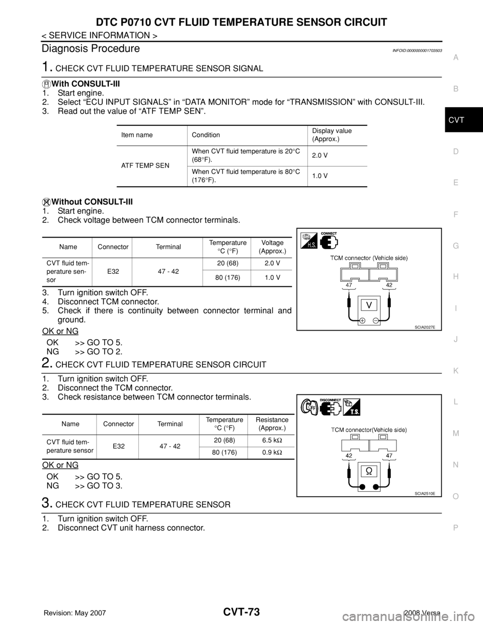
Diagnosis ProcedureINFOID:0000000001703503
1. CHECK CVT FLUID TEMPERATURE SENSOR SIGNAL
With CONSULT-III
1. Start engine.
2. Select “ECU INPUT SIGNALS” in “DATA MONITOR” mode for “TRANSMISSION” with CONSULT-III.
3. Read out the value of “ATF TEMP SEN”.
Without CONSULT-III
1. Start engine.
2. Check voltage between TCM connector terminals.
3. Turn ignition switch OFF.
4. Disconnect TCM connector.
5. Check if there is continuity between connector terminal and
ground.
OK or NG
OK >> GO TO 5.
NG >> GO TO 2.
2. CHECK CVT FLUID TEMPERATURE SENSOR CIRCUIT
1. Turn ignition switch OFF.
2. Disconnect the TCM connector.
3. Check resistance between TCM connector terminals.
OK or NG
OK >> GO TO 5.
NG >> GO TO 3.
3. CHECK CVT FLUID TEMPERATURE SENSOR
1. Turn ignition switch OFF.
2. Disconnect CVT unit harness connector.
Item name ConditionDisplay value
(Approx.)
ATF TEMP SENWhen CVT fluid temperature is 20°C
(68°F).2.0 V
When CVT fluid temperature is 80°C
(176°F).1.0 V
Name Connector TerminalTemperature
°C (°F)Voltage
(Approx.)
CVT fluid tem-
perature sen-
sorE32 47 - 4220 (68) 2.0 V
80 (176) 1.0 V
SCIA2027E
Name Connector TerminalTemperature
°C (°F)Resistance
(Approx.)
CVT fluid tem-
perature sensorE32 47 - 4220 (68) 6.5 kΩ
80 (176) 0.9 kΩ
SCIA2510E
Page 915 of 2771
CVT-76
< SERVICE INFORMATION >
DTC P0715 INPUT SPEED SENSOR CIRCUIT (PRI SPEED SENSOR)
DTC P0715 INPUT SPEED SENSOR CIRCUIT (PRI SPEED SENSOR)
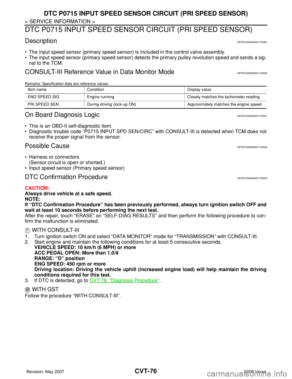
DescriptionINFOID:0000000001703505
• The input speed sensor (primary speed sensor) is included in the control valve assembly.
• The input speed sensor (primary speed sensor) detects the primary pulley revolution speed and sends a sig-
nal to the TCM.
CONSULT-III Reference Value in Data Monitor ModeINFOID:0000000001703506
Remarks: Specification data are reference values.
On Board Diagnosis LogicINFOID:0000000001703507
• This is an OBD-II self-diagnostic item.
• Diagnostic trouble code “P0715 INPUT SPD SEN/CIRC” with CONSULT-III is detected when TCM does not
receive the proper signal from the sensor.
Possible CauseINFOID:0000000001703508
• Harness or connectors
(Sensor circuit is open or shorted.)
• Input speed sensor (Primary speed sensor)
DTC Confirmation ProcedureINFOID:0000000001703509
CAUTION:
Always drive vehicle at a safe speed.
NOTE:
If “DTC Confirmation Procedure” has been previously performed, always turn ignition switch OFF and
wait at least 10 seconds before performing the next test.
After the repair, touch “ERASE” on “SELF-DIAG RESULTS” and then perform the following procedure to con-
firm the malfunction is eliminated.
WITH CONSULT-III
1. Turn ignition switch ON and select “DATA MONITOR” mode for “TRANSMISSION” with CONSULT-III.
2. Start engine and maintain the following conditions for at least 5 consecutive seconds.
VEHICLE SPEED: 10 km/h (6 MPH) or more
ACC PEDAL OPEN: More than 1.0/8
RANGE: “D” position
ENG SPEED: 450 rpm or more
Driving location: Driving the vehicle uphill (increased engine load) will help maintain the driving
conditions required for this test.
3. If DTC is detected, go to CVT-78, "
Diagnosis Procedure" .
WITH GST
Follow the procedure “WITH CONSULT-III”.
Item name Condition Display value
ENG SPEED SIG Engine running Closely matches the tachometer reading.
PRI SPEED SEN During driving (lock-up ON) Approximately matches the engine speed.
Page 917 of 2771
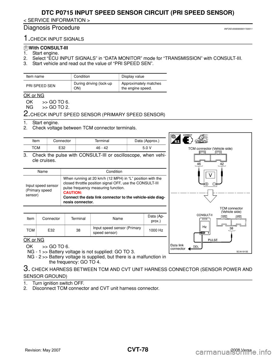
CVT-78
< SERVICE INFORMATION >
DTC P0715 INPUT SPEED SENSOR CIRCUIT (PRI SPEED SENSOR)
Diagnosis Procedure
INFOID:0000000001703511
1.CHECK INPUT SIGNALS
With CONSULT-III
1. Start engine.
2. Select “ECU INPUT SIGNALS” in “DATA MONITOR” mode for “TRANSMISSION” with CONSULT-III.
3. Start vehicle and read out the value of “PRI SPEED SEN”.
OK or NG
OK >> GO TO 6.
NG >> GO TO 2.
2.CHECK INPUT SPEED SENSOR (PRIMARY SPEED SENSOR)
1. Start engine.
2. Check voltage between TCM connector terminals.
3. Check the pulse with CONSULT-III or oscilloscope, when vehi-
cle cruises.
OK or NG
OK >> GO TO 6.
NG - 1 >> Battery voltage is not supplied: GO TO 3.
NG - 2 >> Battery voltage is supplied, but there is a malfunction in
the frequency: GO TO 4.
3. CHECK HARNESS BETWEEN TCM AND CVT UNIT HARNESS CONNECTOR (SENSOR POWER AND
SENSOR GROUND)
1. Turn ignition switch OFF.
2. Disconnect TCM connector and CVT unit harness connector.
Item name Condition Display value
PRI SPEED SENDuring driving (lock-up
ON)Approximately matches
the engine speed.
Item Connector Terminal Data (Approx.)
TCM E32 46 - 42 5.0 V
Name Condition
Input speed sensor
(Primary speed
sensor)When running at 20 km/h (12 MPH) in “L” position with the
closed throttle position signal OFF, use the CONSULT-III
pulse frequency measuring function.
CAUTION:
Connect the data link connector to the vehicle-side diag-
nosis connector.
Item Connector Terminal NameData (Ap-
prox.)
TCM E32 38Input speed sensor (Primary
speed sensor)1000 Hz
SCIA1915E
Page 921 of 2771
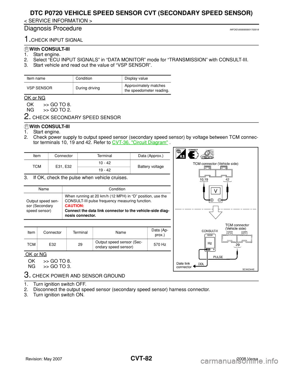
CVT-82
< SERVICE INFORMATION >
DTC P0720 VEHICLE SPEED SENSOR CVT (SECONDARY SPEED SENSOR)
Diagnosis Procedure
INFOID:0000000001703518
1.CHECK INPUT SIGNAL
With CONSULT-III
1. Start engine.
2. Select “ECU INPUT SIGNALS” in “DATA MONITOR” mode for “TRANSMISSION” with CONSULT-III.
3. Start vehicle and read out the value of “VSP SENSOR”.
OK or NG
OK >> GO TO 8.
NG >> GO TO 2.
2. CHECK SECONDARY SPEED SENSOR
With CONSULT-III
1. Start engine.
2. Check power supply to output speed sensor (secondary speed sensor) by voltage between TCM connec-
tor terminals 10, 19 and 42. Refer to CVT-36, "
Circuit Diagram" .
3. If OK, check the pulse when vehicle cruises.
OK or NG
OK >> GO TO 8.
NG >> GO TO 3.
3. CHECK POWER AND SENSOR GROUND
1. Turn ignition switch OFF.
2. Disconnect the output speed sensor (secondary speed sensor) harness connector.
3. Turn ignition switch ON.
Item name Condition Display value
VSP SENSOR During drivingApproximately matches
the speedometer reading.
Item Connector Terminal Data (Approx.)
TCM E31, E3210 - 42
Battery voltage
19 - 42
Name Condition
Output speed sen-
sor (Secondary
speed sensor)When running at 20 km/h (12 MPH) in “D” position, use the
CONSULT-III pulse frequency measuring function.
CAUTION:
Connect the data link connector to the vehicle-side diag-
nosis connector.
Item Connector Terminal NameData (Ap-
prox.)
TCM E32 29Output speed sensor (Sec-
ondary speed sensor)570 Hz
SCIA2344E
Page 926 of 2771
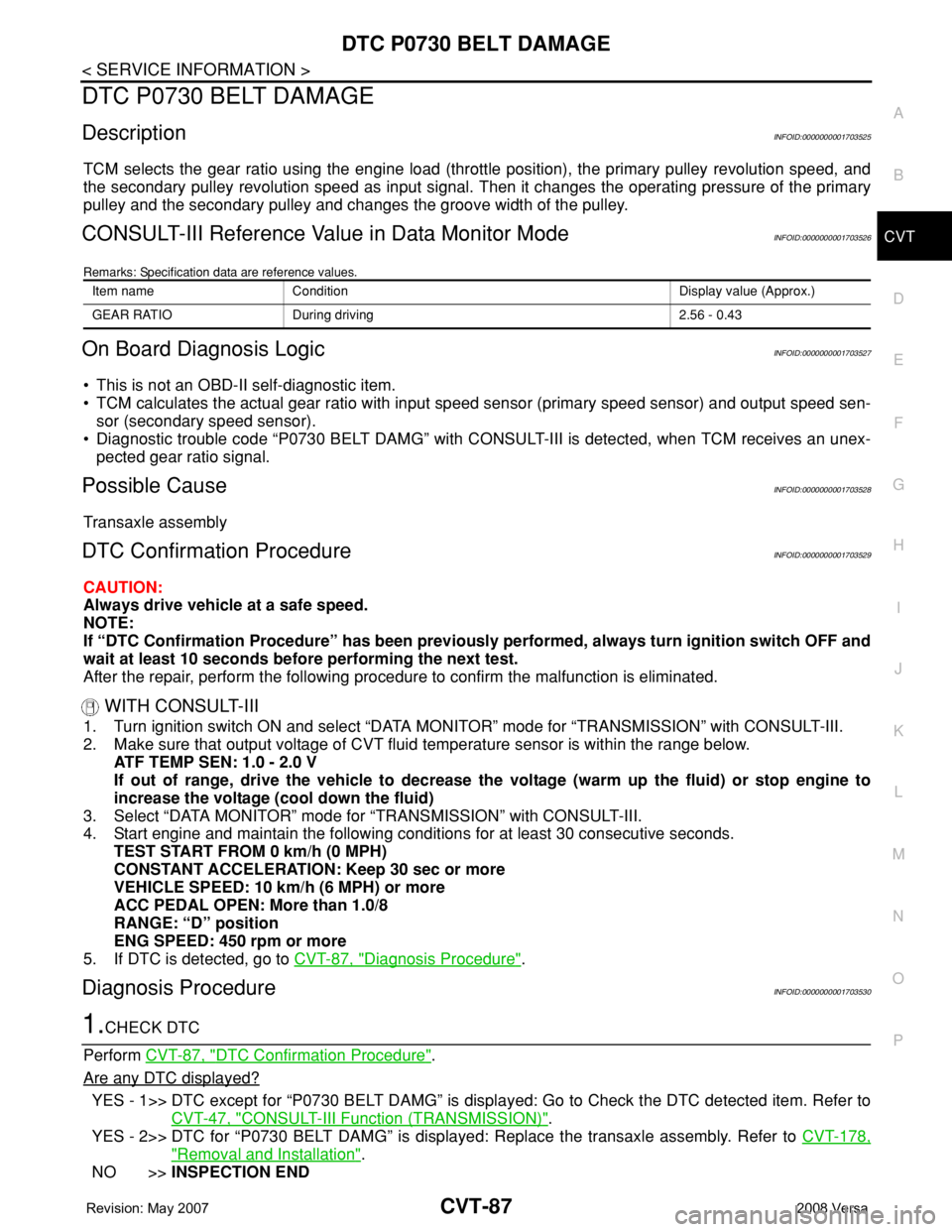
DTC P0730 BELT DAMAGE
CVT-87
< SERVICE INFORMATION >
D
E
F
G
H
I
J
K
L
MA
B
CVT
N
O
P
DTC P0730 BELT DAMAGE
DescriptionINFOID:0000000001703525
TCM selects the gear ratio using the engine load (throttle position), the primary pulley revolution speed, and
the secondary pulley revolution speed as input signal. Then it changes the operating pressure of the primary
pulley and the secondary pulley and changes the groove width of the pulley.
CONSULT-III Reference Value in Data Monitor ModeINFOID:0000000001703526
Remarks: Specification data are reference values.
On Board Diagnosis LogicINFOID:0000000001703527
• This is not an OBD-II self-diagnostic item.
• TCM calculates the actual gear ratio with input speed sensor (primary speed sensor) and output speed sen-
sor (secondary speed sensor).
• Diagnostic trouble code “P0730 BELT DAMG” with CONSULT-III is detected, when TCM receives an unex-
pected gear ratio signal.
Possible CauseINFOID:0000000001703528
Transaxle assembly
DTC Confirmation ProcedureINFOID:0000000001703529
CAUTION:
Always drive vehicle at a safe speed.
NOTE:
If “DTC Confirmation Procedure” has been previously performed, always turn ignition switch OFF and
wait at least 10 seconds before performing the next test.
After the repair, perform the following procedure to confirm the malfunction is eliminated.
WITH CONSULT-III
1. Turn ignition switch ON and select “DATA MONITOR” mode for “TRANSMISSION” with CONSULT-III.
2. Make sure that output voltage of CVT fluid temperature sensor is within the range below.
ATF TEMP SEN: 1.0 - 2.0 V
If out of range, drive the vehicle to decrease the voltage (warm up the fluid) or stop engine to
increase the voltage (cool down the fluid)
3. Select “DATA MONITOR” mode for “TRANSMISSION” with CONSULT-III.
4. Start engine and maintain the following conditions for at least 30 consecutive seconds.
TEST START FROM 0 km/h (0 MPH)
CONSTANT ACCELERATION: Keep 30 sec or more
VEHICLE SPEED: 10 km/h (6 MPH) or more
ACC PEDAL OPEN: More than 1.0/8
RANGE: “D” position
ENG SPEED: 450 rpm or more
5. If DTC is detected, go to CVT-87, "
Diagnosis Procedure".
Diagnosis ProcedureINFOID:0000000001703530
1.CHECK DTC
Perform CVT-87, "
DTC Confirmation Procedure".
Are any DTC displayed?
YES - 1>> DTC except for “P0730 BELT DAMG” is displayed: Go to Check the DTC detected item. Refer to
CVT-47, "
CONSULT-III Function (TRANSMISSION)".
YES - 2>> DTC for “P0730 BELT DAMG” is displayed: Replace the transaxle assembly. Refer to CVT-178,
"Removal and Installation".
NO >>INSPECTION END
Item name Condition Display value (Approx.)
GEAR RATIO During driving 2.56 - 0.43
Page 939 of 2771

CVT-100
< SERVICE INFORMATION >
DTC P0746 PRESSURE CONTROL SOLENOID A PERFORMANCE (LINE PRES-
SURE SOLENOID VALVE)
DTC P0746 PRESSURE CONTROL SOLENOID A PERFORMANCE (LINE
PRESSURE SOLENOID VALVE)
DescriptionINFOID:0000000001703553
• The pressure control solenoid valve A (line pressure solenoid valve) is included in the control valve assem-
bly.
• The pressure control solenoid valve A (line pressure solenoid valve) regulates the oil pump discharge pres-
sure to suit the driving condition in response to a signal sent from the TCM.
CONSULT-III Reference Value in Data Monitor ModeINFOID:0000000001703554
Remarks: Specification data are reference values.
On Board Diagnosis LogicINFOID:0000000001703555
• This is an OBD-II self-diagnostic item.
• Diagnostic trouble code “P0746 PRS CNT SOL/A FCTN” with CONSULT-III is detected under the following
conditions.
- Unexpected gear ratio was detected in the LOW side due to excessively low line pressure.
Possible CauseINFOID:0000000001703556
• Line pressure control system
• Output speed sensor (Secondary speed sensor)
• Input speed sensor (Primary speed sensor)
DTC Confirmation ProcedureINFOID:0000000001703557
CAUTION:
Always drive vehicle at a safe speed.
NOTE:
If “DTC Confirmation Procedure” has been previously performed, always turn ignition switch OFF and
wait at least 10 seconds before performing the next test.
After the repair, touch “ERASE” on “SELF-DIAG RESULTS” and then perform the following procedure to con-
firm the malfunction is eliminated.
WITH CONSULT-III
1. Turn ignition switch ON and select “DATA MONITOR” mode for “TRANSMISSION” with CONSULT-III.
2. Start engine and maintain the following conditions for at least 10 consecutive seconds. Test start from 0
km/h (0 MPH).
ATF TEMP SEN: 1.0 - 2.0 V
ACC PEDAL OPEN: More than 1.0/8
RANGE: “D” position
VEHICLE SPEED: 10 km/h (6 MPH) More than
Driving location: Driving the vehicle uphill (increased engine load) will help maintain the driving
conditions required for this test.
3. If DTC is detected, go to CVT-100, "
Diagnosis Procedure".
WITH GST
Follow the procedure “WITH CONSULT-III”.
Diagnosis ProcedureINFOID:0000000001703558
1.CHECK INPUT SIGNAL
With CONSULT-III
1. Start engine.
2. Select “MAIN SIGNALS” in “DATA MONITOR” mode for “TRANSMISSION” with CONSULT-III.
3. Start vehicle and read out the value of “PRI PRESS”.
Item name Condition Display value (Approx.)
PRI PRESS “N” position idle 0.4 MPa