window motor NISSAN TIIDA 2008 Service Repair Manual
[x] Cancel search | Manufacturer: NISSAN, Model Year: 2008, Model line: TIIDA, Model: NISSAN TIIDA 2008Pages: 2771, PDF Size: 60.61 MB
Page 423 of 2771
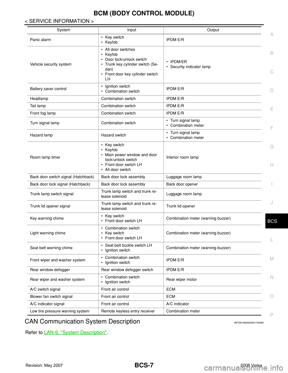
BCM (BODY CONTROL MODULE)
BCS-7
< SERVICE INFORMATION >
C
D
E
F
G
H
I
J
L
MA
B
BCS
N
O
P
CAN Communication System DescriptionINFOID:0000000001704585
Refer to LAN-6, "System Description".
Panic alarm• Key switch
•KeyfobIPDM E/R
Vehicle security system• All door switches
•Keyfob
• Door lock/unlock switch
• Trunk key cylinder switch (Se-
dan)
• Front door key cylinder switch
LH• IPDM/ER
• Security indicator lamp
Battery saver control• Ignition switch
• Combination switchIPDM E/R
Headlamp Combination switch IPDM E/R
Tail lamp Combination switch IPDM E/R
Front fog lamp Combination switch IPDM E/R
Turn signal lamp Combination switch• Turn signal lamp
• Combination meter
Hazard lamp Hazard switch• Turn signal lamp
• Combination meter
Room lamp timer• Key switch
•Keyfob
• Main power window and door
lock/unlock switch
• Front door switch LH
• All door switchInterior room lamp
Back door switch signal (Hatchback) Back door lock assembly Luggage room lamp
Back door lock signal (Hatchback) Back door lock assembly Back door opener
Trunk lamp switch signalTrunk lamp switch and trunk re-
lease solenoidLuggage room lamp
Trunk lid opener signalTrunk lamp switch and trunk re-
lease solenoidTrunk lid opener
Key warning chime• Key switch
• Front door switch LHCombination meter (warning buzzer)
Light warning chime• Combination switch
• Key switch
• Front door switch LHCombination meter (warning buzzer)
Seat belt warning chime• Seat belt buckle switch LH
• Ignition switchCombination meter (warning buzzer)
Front wiper and washer system• Combination switch
• Ignition switchIPDM E/R
Rear window defogger Rear window defogger switch IPDM E/R
Rear wiper and washer system• Combination switch
• Ignition switchRear wiper motor
A/C switch signal Front air control ECM
Blower fan switch signal Front air control ECM
A/C indicator signal Front air control A/C indicator
Low tire pressure warning system Remote keyless entry receiver Combination meterSystem Input Output
Page 1902 of 2771

GW-1
BODY
C
D
E
F
G
H
J
K
L
M
SECTION GW
A
B
GW
N
O
P
CONTENTS
GLASSES, WINDOW SYSTEM & MIRRORS
SERVICE INFORMATION ............................3
PRECAUTIONS ...................................................3
Precaution for Supplemental Restraint System
(SRS) "AIR BAG" and "SEAT BELT PRE-TEN-
SIONER" ...................................................................
3
Precaution for Procedure without Cowl Top Cover ......3
Handling for Adhesive and Primer ............................3
PREPARATION ...................................................4
Commercial Service Tool ..........................................4
SQUEAK AND RATTLE TROUBLE DIAG-
NOSES ................................................................
5
Work Flow .................................................................5
Generic Squeak and Rattle Troubleshooting ............7
Diagnostic Worksheet ...............................................9
WINDSHIELD GLASS ........................................11
Removal and Installation .........................................11
OPERA WINDOW GLASS .................................13
Removal and Installation .........................................13
REAR WINDOW GLASS AND MOLDING .........15
Removal and Installation .........................................15
POWER WINDOW SYSTEM ..............................18
Component Parts and Harness Connector Loca-
tion ..........................................................................
18
System Description .................................................18
CAN Communication System Description ...............22
Schematic ...............................................................22
Wiring Diagram - WINDOW- ...................................23
Main Power Window and Door Lock/Unlock
Switch Harness Connector Terminal Layout ...........
26
Terminal and Reference Value for Main Power
Window and Door Lock/Unlock Switch ...................
27
Terminal and Reference Value for BCM .................28
Work Flow ...............................................................28
CONSULT-III Function (BCM) .................................28
Power Window Auto Operation Initialization ...........29
Trouble Diagnosis Symptom Chart ..........................29
BCM Power Supply and Ground Circuit Inspection
....
30
Main Power Window and Door Lock/Unlock
Switch Power Supply and Ground Circuit Inspec-
tion ...........................................................................
30
Front Power Window Motor LH Circuit Inspection ....31
Front Power Window RH Circuit Inspection (Pow-
er Window and Door Lock/Unlock Switch RH Op-
eration) ....................................................................
32
Front Power Window Motor RH Circuit Inspection ....32
Encoder Circuit Inspection .......................................34
Door Switch Check ..................................................36
Rear Power Window LH Circuit Inspection (Rear
Power Window Switch LH Operation) .....................
37
Rear Power Window RH Circuit Inspection (Rear
Power Window Switch RH Operation) .....................
38
Rear Power Window Motor LH Circuit Inspection ....38
Rear Power Window Motor RH Circuit Inspection ....40
FRONT DOOR GLASS AND REGULATOR .....42
Removal and Installation .........................................42
Disassembly and Assembly .....................................44
Inspection after Installation ......................................44
REAR DOOR GLASS AND REGULATOR .......46
Removal and Installation .........................................46
Disassembly and Assembly .....................................48
Inspection after Installation ......................................48
REAR WINDOW DEFOGGER ..........................49
Component Parts and Harness Connector Loca-
tion ...........................................................................
49
System Description ..................................................49
CAN Communication System Description ...............50
Wiring Diagram - DEF - ...........................................51
Terminal and Reference Value for BCM ..................52
Terminal and Reference Value for IPDM E/R ..........52
Work Flow ................................................................53
CONSULT-III Function (BCM) .................................53
Trouble Diagnosis Symptom Chart ..........................53
Page 1917 of 2771
GW-16
< SERVICE INFORMATION >
REAR WINDOW GLASS AND MOLDING
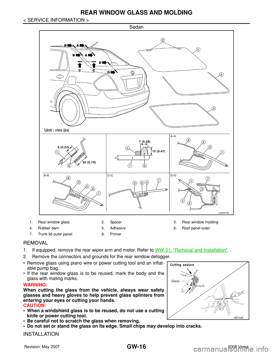
Sedan
REMOVAL
1. If equipped, remove the rear wiper arm and motor. Refer to WW-31, "Removal and Installation" .
2. Remove the connectors and grounds for the rear window defogger.
• Remove glass using piano wire or power cutting tool and an inflat-
able pump bag.
• If the rear window glass is to be reused, mark the body and the
glass with mating marks.
WARNING:
When cutting the glass from the vehicle, always wear safety
glasses and heavy gloves to help prevent glass splinters from
entering your eyes or cutting your hands.
CAUTION:
• When a windshield glass is to be reused, do not use a cutting
knife or power cutting tool.
• Be careful not to scratch the glass when removing.
• Do not set or stand the glass on its edge. Small chips may develop into cracks.
INSTALLATION
LIIA2913E
1. Rear window glass 2. Spacer 3. Rear window molding
4. Rubber dam 5. Adhesive 6. Roof panel outer
7. Trunk lid outer panel 8. Primer
SBF034B
Page 1919 of 2771

GW-18
< SERVICE INFORMATION >
POWER WINDOW SYSTEM
POWER WINDOW SYSTEM
Component Parts and Harness Connector LocationINFOID:0000000001704138
System DescriptionINFOID:0000000001704139
Power is supplied at all times
• through 40A fusible link (letter g , located in the fuse and fusible link box)
• to BCM terminal 70.
With ignition switch in ON or START position, power is supplied
• through 10A fuse [No. 6, located in the fuse block (J/B)]
• to BCM terminal 38
1. Main power window and door lock/
unlock switch D7, D82. Power window and door lock/unlock
switch RH D1053. Rear power window switch LH D203,
RH D303
4. BCM M18, M19, M20 (view with
glove box removed)5. Front power window motor LH D9,
RH D1046. Rear power window motor LH D204,
RH D304
7. Front door switch LH B8, RH B108
LIIA2529E
Page 1920 of 2771

POWER WINDOW SYSTEM
GW-19
< SERVICE INFORMATION >
C
D
E
F
G
H
J
K
L
MA
B
GW
N
O
P
• through BCM terminal 68
• to main power window and door lock/unlock switch terminal 10
• to power window and door lock/unlock switch RH terminal 8 and
• to rear power window switches LH and RH terminal 1.
Ground is supplied
• to BCM terminal 67
• to main power window and door lock/unlock switch terminal 17 and
• to power window and door lock/unlock switch RH terminal 3
• through body grounds M57 and M61.
With ignition switch in ACC or ON position, power is supplied
• through 10A fuse [No. 20, located in the fuse block (J/B)]
• to BCM terminal 11.
MANUAL OPERATION
Front Door LH
WINDOW UP
When the front LH switch in the main power window and door lock/unlock switch is pulled in the up position,
power is supplied
• through main power window and door lock/unlock switch terminal 8
• to front power window motor LH terminal 2.
Ground is supplied
• through main power window and door lock/unlock switch terminal 11
• to front power window motor LH terminal 3.
Then, the motor raises the window until the switch is released.
WINDOW DOWN
When the front LH switch in the main power window and door lock/unlock switch is pressed in the down posi-
tion, power is supplied
• through main power window and door lock/unlock switch terminal 11
• to front power window motor LH terminal 3.
Ground is supplied
• through main power window and door lock/unlock switch terminal 8
• to front power window motor LH terminal 2.
Then, the motor lowers the window until the switch is released.
Front Door RH
POWER WINDOW AND DOOR LOCK/UNLOCK SWITCH RH OPERATION
WINDOW UP
When the power window and door lock/unlock switch RH is pulled in the up position, power is supplied
• through power window and door lock/unlock switch RH terminal 7
• to front power window motor RH terminal 2.
Ground is supplied
• through power window and door lock/unlock switch RH terminal 6
• to front power window motor RH terminal 1.
Then, the motor raises the window until the switch is released.
WINDOW DOWN
When the power window and door lock/unlock switch RH is pressed in the down position, power is supplied
• through power window and door lock/unlock switch RH terminal 6
• to front power window motor RH terminal 1.
Ground is supplied
• through power window and door lock/unlock switch RH terminal 7
• to front power window motor RH terminal 2.
Then, the motor lowers the window until the switch is released.
MAIN POWER WINDOW AND DOOR LOCK/UNLOCK SWITCH OPERATION
WINDOW UP
When the main power window and door lock/unlock switch (front RH) is pulled in the up position, power is sup-
plied
• through main power window and door lock/unlock switch terminal 16
• to power window and door lock/unlock switch RH terminal 12
• through power window and door lock/unlock switch RH terminal 7
• to front power window motor RH terminal 2.
Ground is supplied
Page 1921 of 2771

GW-20
< SERVICE INFORMATION >
POWER WINDOW SYSTEM
• through main power window and door lock/unlock switch terminal 12
• to power window and door lock/unlock switch RH terminal 11
• through power window and door lock/unlock switch LH terminal 6
• to front power window motor RH terminal 1.
Then, the motor raises the window until the switch is released.
WINDOW DOWN
When the main power window and door lock/unlock switch (front RH) is pressed in the down position, power is
supplied
• through main power window and door lock/unlock switch terminal 12
• to power window and door lock/unlock switch LH terminal 11
• through power window and door lock/unlock switch LH terminal 6
• to front power window motor RH terminal 1.
Ground is supplied
• through main power window and door lock/unlock switch terminal 16
• to power window and door lock/unlock switch RH terminal 12
• through power window and door lock/unlock switch LH terminal 7
• to front power window motor RH terminal 2.
Then, the motor lowers the window until the switch is released.
Rear Door (LH or RH)
REAR POWER WINDOW SWITCH LH OR RH OPERATION
WINDOW UP
When the rear power window switch LH or RH is pulled in the up position, power is supplied
• through rear power window switch LH or RH terminal 5
• to rear power window motor LH or RH terminal 2.
Ground is supplied
• through rear power window switch LH or RH terminal 4
• to rear power window motor LH or RH terminal 1.
Then, the motor raises the window until the switch is released.
WINDOW DOWN
When the rear power window switch LH or RH is pressed in the down position, power is supplied
• through rear power window switch LH or RH terminal 4
• to rear power window motor LH or RH terminal 1.
Ground is supplied
• through rear power window switch LH or RH terminal 5
• to rear power window motor LH or RH terminal 2.
Then, the motor lowers the window until the switch is released.
MAIN POWER WINDOW AND DOOR LOCK/UNLOCK SWITCH OPERATION
WINDOW UP
When the main power window and door lock/unlock switch (rear LH) is pulled in the up position, power is sup-
plied
• through main power window and door lock/unlock switch terminal 1
• to rear power window switch LH terminal 2
• through rear power window switch LH terminal 5
• to rear power window motor LH terminal 2.
Ground is supplied
• through main power window and door lock/unlock switch terminal 3
• to rear power window switch LH terminal 3
• through rear power window switch LH terminal 4
• to rear power window motor LH terminal 1.
Then, the motor raises the window until the switch is released.
When the main power window and door lock/unlock switch (rear RH) is pulled in the up position, power is sup-
plied
• through main power window and door lock/unlock switch terminal 7
• to rear power window switch RH terminal 2
• through rear power window switch RH terminal 5
• to rear power window motor RH terminal 2.
Ground is supplied
• through main power window and door lock/unlock switch terminal 5
• through rear power window switch RH terminal 3
• to rear power window switch RH terminal 4
• to rear power window motor RH terminal 1.
Page 1922 of 2771
POWER WINDOW SYSTEM
GW-21
< SERVICE INFORMATION >
C
D
E
F
G
H
J
K
L
MA
B
GW
N
O
P
Then, the motor raises the window until the switch is released.
WINDOW DOWN
When the main power window and door lock/unlock switch (rear LH) is pressed in the down position, power is
supplied
• through main power window and door lock/unlock switch terminal 3
• to rear power window switch LH terminal 3
• through rear power window switch LH terminal 4
• to rear power window motor LH terminal 1.
Ground is supplied
• through main power window and door lock/unlock switch terminal 1
• to rear power window switch LH terminal 2
• through rear power window switch LH terminal 5
• to rear power window motor LH terminal 2.
Then, the motor lowers the window until the switch is released.
When the main power window and door lock/unlock switch (rear RH) is pressed in the down position, power is
supplied
• through main power window and door lock/unlock switch terminal 5
• to rear power window switch RH terminal 3
• through rear power window switch RH terminal 4
• to rear power window motor RH terminal 1.
Ground is supplied
• through main power window and door lock/unlock switch terminal 7
• to rear power window switch RH terminal 2
• through rear power window switch RH terminal 5
• to rear power window motor RH terminal 2.
Then, the motor lowers the window until the switch is released.
AUTO OPERATION
The power window AUTO feature enables the driver to open the window without holding the window switch in
the down position.
POWER WINDOW LOCK
The power window lock is designed to lock operation of all windows except for front door window LH.
When in the lock position, the power window lock disables power window and door lock/unlock switch RH and
rear power window switch LH and RH by disconnecting switch ground signal. This prevents the power window
motors from operating.
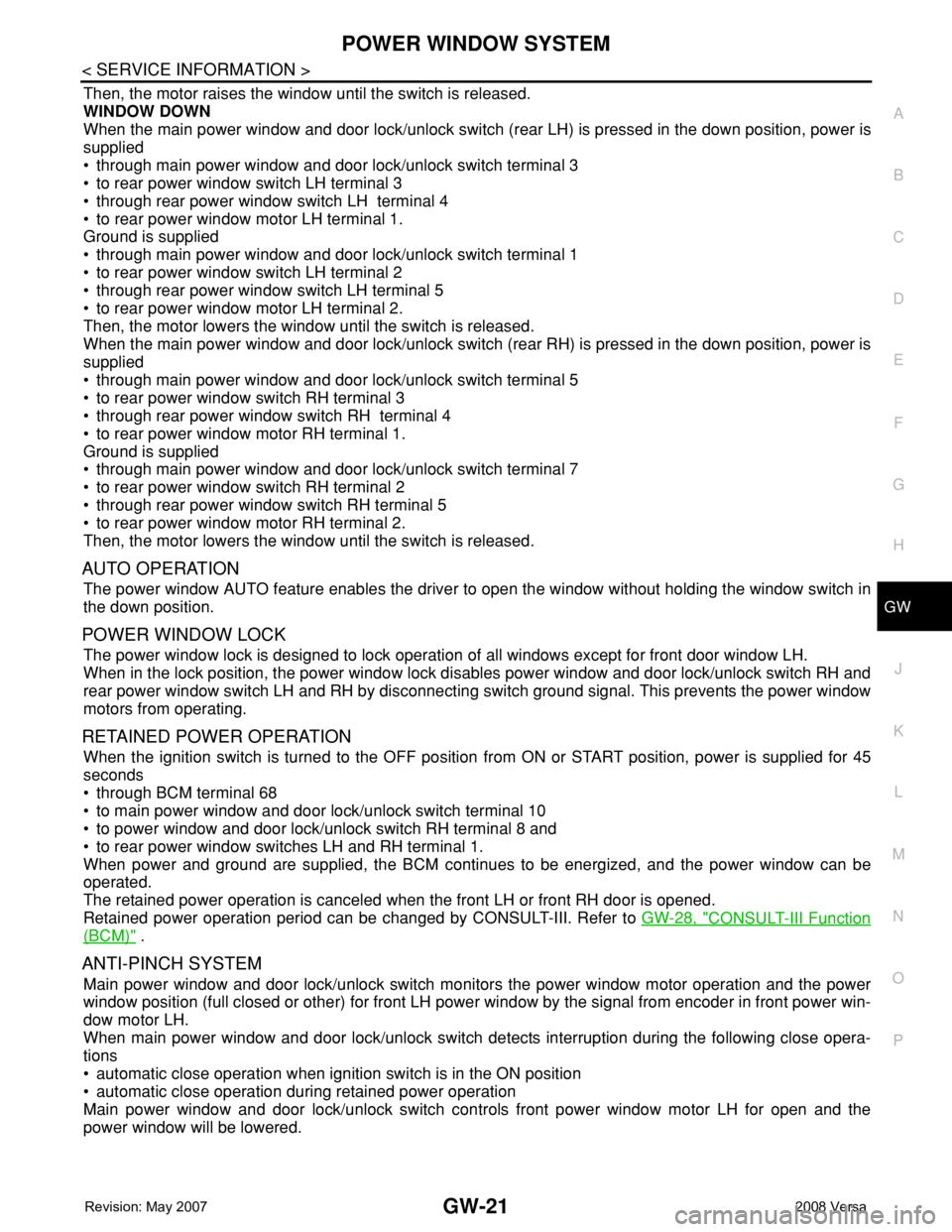
RETAINED POWER OPERATION
When the ignition switch is turned to the OFF position from ON or START position, power is supplied for 45
seconds
• through BCM terminal 68
• to main power window and door lock/unlock switch terminal 10
• to power window and door lock/unlock switch RH terminal 8 and
• to rear power window switches LH and RH terminal 1.
When power and ground are supplied, the BCM continues to be energized, and the power window can be
operated.
The retained power operation is canceled when the front LH or front RH door is opened.
Retained power operation period can be changed by CONSULT-III. Refer to GW-28, "
CONSULT-III Function
(BCM)" .
ANTI-PINCH SYSTEM
Main power window and door lock/unlock switch monitors the power window motor operation and the power
window position (full closed or other) for front LH power window by the signal from encoder in front power win-
dow motor LH.
When main power window and door lock/unlock switch detects interruption during the following close opera-
tions
• automatic close operation when ignition switch is in the ON position
• automatic close operation during retained power operation
Main power window and door lock/unlock switch controls front power window motor LH for open and the
power window will be lowered.
Page 1928 of 2771
POWER WINDOW SYSTEM
GW-27
< SERVICE INFORMATION >
C
D
E
F
G
H
J
K
L
MA
B
GW
N
O
P
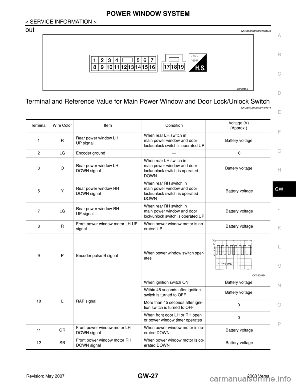
outINFOID:0000000001704143
Terminal and Reference Value for Main Power Window and Door Lock/Unlock Switch
INFOID:0000000001704144
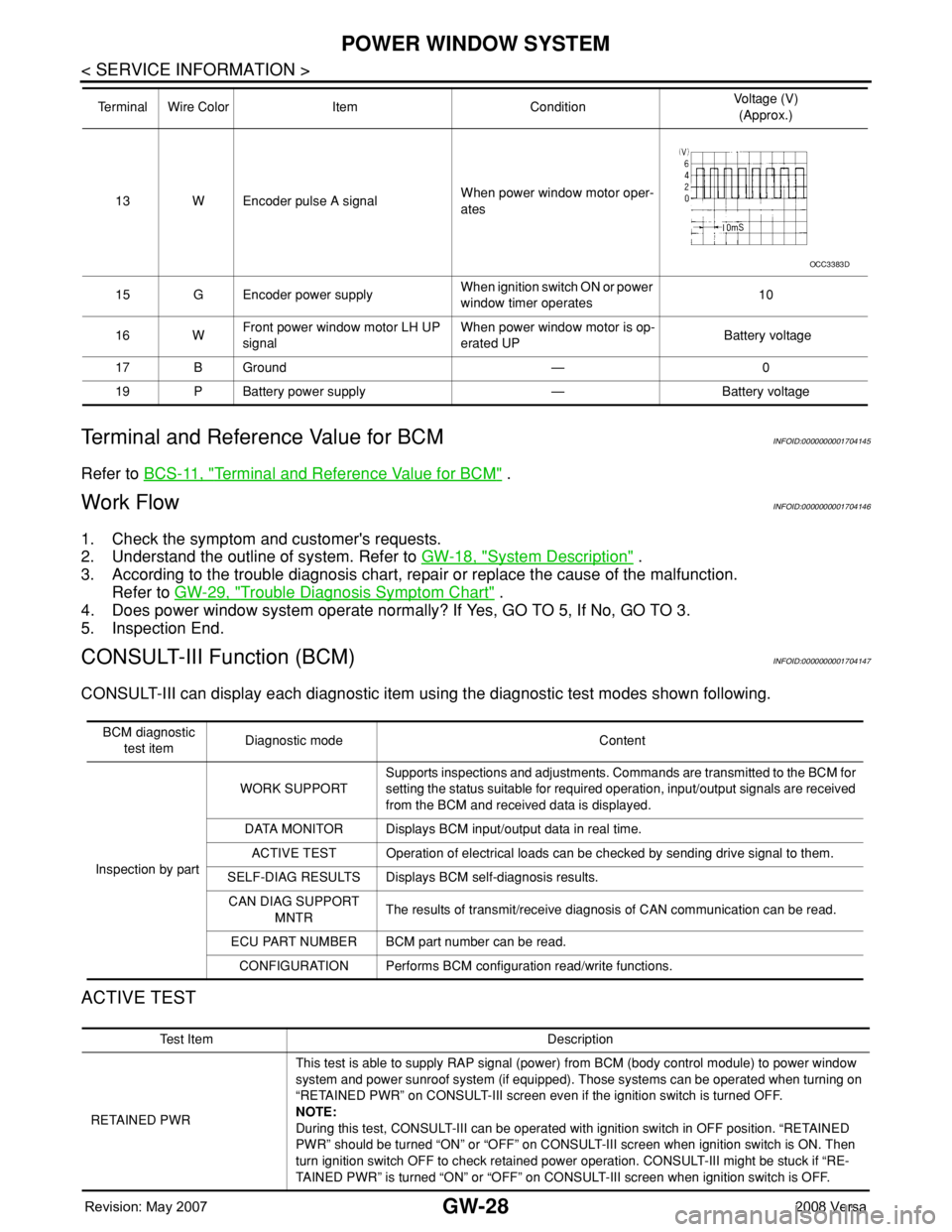
LIIA2455E
Terminal Wire Color Item ConditionVoltage (V)
(Approx.)
1RRear power window LH
UP signalWhen rear LH switch in
main power window and door
lock/unlock switch is operated UPBattery voltage
2 LG Encoder ground — 0
3ORear power window LH
DOWN signalWhen rear LH switch in
main power window and door
lock/unlock switch is operated
DOWNBattery voltage
5YRear power window RH
DOWN signalWhen rear RH switch in
main power window and door
lock/unlock switch is operated
DOWN Battery voltage
7LGRear power window RH
UP signalWhen rear RH switch in
main power window and door
lock/unlock switch is operated UP Battery voltage
8RFront power window motor LH UP
signalWhen power window motor is op-
erated UP Battery voltage
9 P Encoder pulse B signalWhen power window switch oper-
ates
10 L RAP signalWhen ignition switch ON Battery voltage
Within 45 seconds after ignition
switch is turned to OFFBattery voltage
More than 45 seconds after igni-
tion switch is turned to OFF0
When front door LH or RH open
or power window timer operates0
11 G RFront power window motor LH
DOWN signalWhen power window motor is op-
erated DOWN Battery voltage
12 SBFront power window motor RH
DOWN signalWhen power window motor is op-
erated DOWN Battery voltage
OCC3383D
Page 1929 of 2771
GW-28
< SERVICE INFORMATION >
POWER WINDOW SYSTEM
Terminal and Reference Value for BCM
INFOID:0000000001704145
Refer to BCS-11, "Terminal and Reference Value for BCM" .
Work FlowINFOID:0000000001704146
1. Check the symptom and customer's requests.
2. Understand the outline of system. Refer to GW-18, "
System Description" .
3. According to the trouble diagnosis chart, repair or replace the cause of the malfunction.
Refer to GW-29, "
Trouble Diagnosis Symptom Chart" .
4. Does power window system operate normally? If Yes, GO TO 5, If No, GO TO 3.
5. Inspection End.
CONSULT-III Function (BCM)INFOID:0000000001704147
CONSULT-III can display each diagnostic item using the diagnostic test modes shown following.
ACTIVE TEST
13 W Encoder pulse A signalWhen power window motor oper-
ates
15 G Encoder power supplyWhen ignition switch ON or power
window timer operates10
16 WFront power window motor LH UP
signalWhen power window motor is op-
erated UP Battery voltage
17 B Ground — 0
19 P Battery power supply — Battery voltage Terminal Wire Color Item ConditionVoltage (V)
(Approx.)
OCC3383D
BCM diagnostic
test itemDiagnostic mode Content
Inspection by partWORK SUPPORTSupports inspections and adjustments. Commands are transmitted to the BCM for
setting the status suitable for required operation, input/output signals are received
from the BCM and received data is displayed.
DATA MONITOR Displays BCM input/output data in real time.
ACTIVE TEST Operation of electrical loads can be checked by sending drive signal to them.
SELF-DIAG RESULTS Displays BCM self-diagnosis results.
CAN DIAG SUPPORT
MNTRThe results of transmit/receive diagnosis of CAN communication can be read.
ECU PART NUMBER BCM part number can be read.
CONFIGURATION Performs BCM configuration read/write functions.
Te s t I t e m D e s c r i p t i o n
RETAINED PWRThis test is able to supply RAP signal (power) from BCM (body control module) to power window
system and power sunroof system (if equipped). Those systems can be operated when turning on
“RETAINED PWR” on CONSULT-III screen even if the ignition switch is turned OFF.
NOTE:
During this test, CONSULT-III can be operated with ignition switch in OFF position. “RETAINED
PWR” should be turned “ON” or “OFF” on CONSULT-III screen when ignition switch is ON. Then
turn ignition switch OFF to check retained power operation. CONSULT-III might be stuck if “RE-
TAINED PWR” is turned “ON” or “OFF” on CONSULT-III screen when ignition switch is OFF.
Page 1930 of 2771

POWER WINDOW SYSTEM
GW-29
< SERVICE INFORMATION >
C
D
E
F
G
H
J
K
L
MA
B
GW
N
O
P
WORK SUPPORT
DATA MONITOR
Power Window Auto Operation InitializationINFOID:0000000001871741
1. Turn the ignition switch ON.
2. Open the window—all the way DOWN.
3. Pull all the way UP on the switch and hold (close the window).
• Continue holding the switch all the way UP for 4 seconds after the window is closed.
4. Confirm the window is now operating correctly.
NOTE:
• If the window is still not operating correctly, refer to GW-29, "
Trouble Diagnosis Symptom Chart".
• The above initialization procedure must be performed if any of the following occur:
- Battery cable is disconnected
- Power window switch connector is disconnected
- Power window regulator is replaced
- Power window motor is replaced
- Window glass is removed
- Window glass run rubber is replaced
- Power window fuse is blown
- Window is partly opened and/or closed many times without being fully closed.
Trouble Diagnosis Symptom ChartINFOID:0000000001704148
Check that other systems using the signal of the following systems operate normally.
Work item Description
RETAINED PWRRAP signal’s power supply period can be changed by mode setting. Selects RAP signal’s power
supply period between three steps
• MODE1 (45 sec.)/MODE2 (OFF)/MODE3 (2 min.).
Work item Description
IGN ON SW Indicates (ON/OFF) condition of ignition switch
DOOR SW-DR Indicates (ON/OFF) condition of front door switch LH
DOOR SW-AS Indicates (ON/OFF) condition of front door switch RH
Symptom Repair order Refer to page
None of the power windows can be operated using any switch1. BCM power supply and ground circuit checkBCS-15
2. Main power window and door lock/unlock
power supply and ground circuit checkGW-30
3. Replace main power window and door lock/
unlock switchEI-32
Front power window LH alone does not operate1. Front power window motor LH circuit checkGW-312. Replace main power window and door lock/
unlock switchEI-32
Front power window RH does not operate from power window and
door lock/unlock switch RH only1. Front power window RH circuit check (power
window and door lock/unlock switch RH opera-
tion)GW-32
Front power window RH does not operate from main power window
and door lock/unlock switch only1. Replace main power window and door lock/
unlock switchEI-32
Front power window RH does not operate from any switch 1. Front power window motor RH circuit checkGW-32