coolant temperature NISSAN TIIDA 2009 Service Repair Manual
[x] Cancel search | Manufacturer: NISSAN, Model Year: 2009, Model line: TIIDA, Model: NISSAN TIIDA 2009Pages: 4331, PDF Size: 58.04 MB
Page 3762 of 4331
ENGINE MAINTENANCE (HR16DE)
MA-19
< SERVICE INFORMATION >
C
D E
F
G H
I
J
K
M A
B MA
N
O P
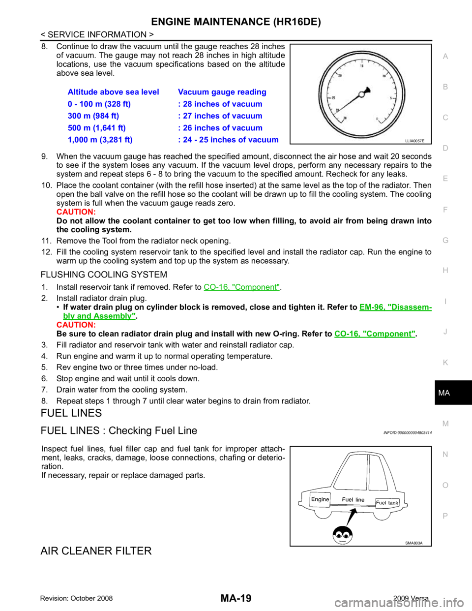
8. Continue to draw the vacuum until the gauge reaches 28 inches
of vacuum. The gauge may not reach 28 inches in high altitude
locations, use the vacuum specifications based on the altitude
above sea level.
9. When the vacuum gauge has reached the specified amount, disconnect the air hose and wait 20 seconds
to see if the system loses any vacuum. If the vacuum level drops, perform any necessary repairs to the
system and repeat steps 6 - 8 to br ing the vacuum to the specified amount. Recheck for any leaks.
10. Place the coolant container (with the refill hose inserted) at the same level as the top of the radiator. Then
open the ball valve on the refill hose so the coolant will be drawn up to fill the cooling system. The cooling
system is full when the vacuum gauge reads zero.
CAUTION:
Do not allow the coolant container to get too low when filling, to avoid air from being drawn into
the cooling system.
11. Remove the Tool from the radiator neck opening.
12. Fill the cooling system reservoir tank to the specif ied level and install the radiator cap. Run the engine to
warm up the cooling system and top up the system as necessary.
FLUSHING COOLING SYSTEM 1. Install reservoir tank if removed. Refer to CO-16, " Component " .
2. Install radiator drain plug. •If water drain plug on cylinder block is removed, close and tighten it. Refer to EM-96, " Disassem-
bly and Assembly " .
CAUTION:
Be sure to clean radiator drain plug and install with new O-ring. Refer to CO-16, " Component " .
3. Fill radiator and reservoir tank with water and reinstall radiator cap.
4. Run engine and warm it up to normal operating temperature.
5. Rev engine two or three times under no-load.
6. Stop engine and wait until it cools down.
7. Drain water from the cooling system.
8. Repeat steps 1 through 7 until clear water begins to drain from radiator.
FUEL LINES
FUEL LINES : Checking Fuel Line INFOID:0000000004803414
Inspect fuel lines, fuel filler cap and fuel tank for improper attach-
ment, leaks, cracks, damage, loos e connections, chafing or deterio-
ration.
If necessary, repair or replace damaged parts.
AIR CLEANER FILTER Altitude above sea level Vacuum gauge reading
0 - 100 m (328 ft) : 28 inches of vacuum
300 m (984 ft) : 27 inches of vacuum
500 m (1,641 ft) : 26 inches of vacuum
1,000 m (3,281 ft) : 24 - 25 inches of vacuum LLIA0057E
SMA803A
Page 3938 of 4331
MTC
N
O P
YES >> GO TO 6.
NO >> Adjust or replace air mix door cable. Refer to MTC-64, " Air Mix Door Cable Adjustment " .
OK >> GO TO 7.
NG >> Repair air leaks. YES >> GO TO 8.
NO >> Both hoses warm: GO TO 9. Component Inspection " (MR TYPE 1),
EC-1196," Component Inspection " (MR TYPE 2) or
EC-169, " Component Inspection " (HR16DE).
OK or NG OK >> System OK.
NG >> Repair or replace as necessary. Retest. OK >> GO TO 10.
NG >> Repair /replace as necessary. Retest GO TO 7. Changing Engine Coolant " (HR16DE) or
CO-35, " Changing Engine Coolant " (MR18DE) .
4. Start engine and warm it up to normal operating temperature.
5. Touch both the inlet and outlet heater hoses.
Is the inlet hose hot and the outlet hose warm? YES >> System OK.
NO >> Replace heater core and refill engine coolant. Refer to MTC-67, " Removal and Installation " .
Noise INFOID:0000000004307075
SYMPTOM: Noise
INSPECTION FLOW
Page 4028 of 4331
PG
N
O P
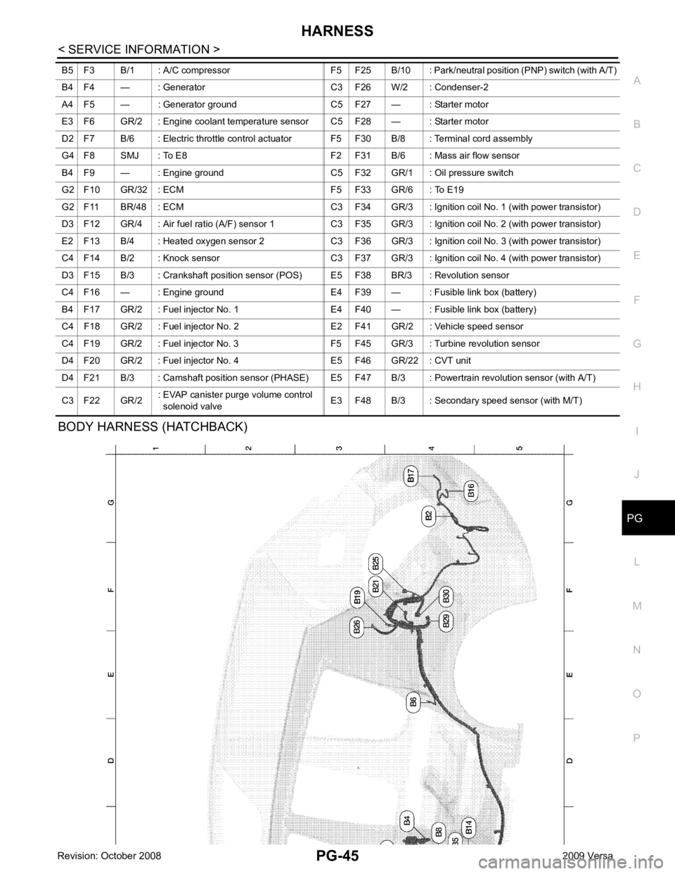
BODY HARNESS (HATCHBACK) B5 F3 B/1 : A/C compressor F5 F25 B/10 : Park/n
eutral position (PNP) switch (with A/T)
B4 F4 — : Generator C3 F26 W/2 : Condenser-2
A4 F5 — : Generator ground C5 F27 — : Starter motor
E3 F6 GR/2 : Engine coolant temperature sensor C5 F28 — : Starter motor
D2 F7 B/6 : Electric throttle control actuator F5 F30 B/8 : Terminal cord assembly
G4 F8 SMJ : To E8 F2 F31 B/6 : Mass air flow sensor
B4 F9 — : Engine ground C5 F32 GR/1 : Oil pressure switch
G2 F10 GR/32 : ECM F5 F33 GR/6 : To E19
G2 F11 BR/48 : ECM C3 F34 GR/3 : Ignition coil No. 1 (with power transistor)
D3 F12 GR/4 : Air fuel ratio (A/F) sensor 1 C3 F35 GR/3 : Ignition coil No. 2 (with power transistor)
E2 F13 B/4 : Heated oxygen sensor 2 C3 F36 GR/3 : Ignition coil No. 3 (with power transistor)
C4 F14 B/2 : Knock sensor C3 F37 GR/3 : Ignition coil No. 4 (with power transistor)
D3 F15 B/3 : Crankshaft position sensor (POS) E5 F38 BR/3 : Revolution sensor
C4 F16 — : Engine ground E4 F39 — : Fusible link box (battery)
B4 F17 GR/2 : Fuel injector No. 1 E4 F40 — : Fusible link box (battery)
C4 F18 GR/2 : Fuel injector No. 2 E2 F41 GR/2 : Vehicle speed sensor
C4 F19 GR/2 : Fuel injector No. 3 F5 F45 GR/3 : Turbine revolution sensor
D4 F20 GR/2 : Fuel injector No. 4 E5 F46 GR/22 : CVT unit
D4 F21 B/3 : Camshaft position sensor (PHASE) E5 F4 7 B/3 : Powertrain revolution sensor (with A/T)
C3 F22 GR/2 : EVAP canister purge volume control
solenoid valve E3 F48 B/3 : Secondary speed sensor (with M/T)
Page 4040 of 4331

PG
N
O P
Wiring Diagram Codes (Cell Codes)
INFOID:0000000004306667
Use the chart below to find out what each wiring diagram code stands for.
Refer to the wiring diagram code in the alphabetical index to find the location (page number) of each wiring
diagram. D4 D405 W/4 : Back door lock assembly C2 D413 B/1 : Rear window defogger (-)
D4 D406 W/2 : Back door request switch F3 D414 — : Body ground
E2 D407 W/2 : High mounted stop lamp Code Section Wiring Diagram Name
ABS BRC Anti-lock Brake System
A/C,M MTC Manual Air Conditioner
APPS1 EC Accelerator Pe dal Position Sensor
A/F EC Air Fuel Ratio Sensor 1
A/FH EC Air Fuel Ratio Sensor 1 Heater
APPS2 EC Accelerator Pe dal Position Sensor
APPS3 EC Accelerator Pe dal Position Sensor
ASC/BS EC ASCD Brake Switch
ASC/SW EC ASCD Steering Switch
ASCBOF EC ASCD Brake Switch
ASCIND EC ASCD Indicator
AT/IND DI A/T Indicator Lamp
AUDIO AV Audio
BACK/L LT Back-up Lamp
BA/FTS AT A/T Fluid Temperature Sensor and TCM Power Supply
B/DOOR BL Back Door Opener
BRK/SW EC Brake Switch
CAN AT CAN Communication Line
CAN CVT CAN Comm unication Line
CAN EC CAN Communication Line
CAN LAN CAN System
CHARGE SC Charging System
CHIME DI Warning Chime
COOL/F EC Cooling Fan Control
COMBSW LT Combination Switch
CVTIND DI CVT Indicator Lamp
D/LOCK BL Power Door Lock
DEF GW Rear Window Defogger
DTRL LT Headlamp - Wi th Daytime Light System
ECTS EC Engine Coolant Temperature Sensor
ENGSS AT Engine Speed Signal
EPS STC Electronic Controlled Power Steering
ETC1 EC Electric Throttle Control Function
ETC2 EC Throttle Control Motor Relay
ETC3 EC Throttle Control Motor
F/FOG LT Front Fog Lamp
F/PUMP EC Fuel Pump
FTS AT A/T Fluid Temperature Sensor
FTS CVT CVT Fluid Temperature Sensor Circuit
FTTS EC Fuel Tank Temperature Sensor
FUEL EC Fuel Ignition System Function
HEATER MTC Heater System