window NISSAN TIIDA 2009 Service User Guide
[x] Cancel search | Manufacturer: NISSAN, Model Year: 2009, Model line: TIIDA, Model: NISSAN TIIDA 2009Pages: 4331, PDF Size: 58.04 MB
Page 526 of 4331
REMOTE KEYLESS ENTRY SYSTEM
BL-65
< SERVICE INFORMATION >
C
D E
F
G H
J
K L
M A
B BL
N
O P
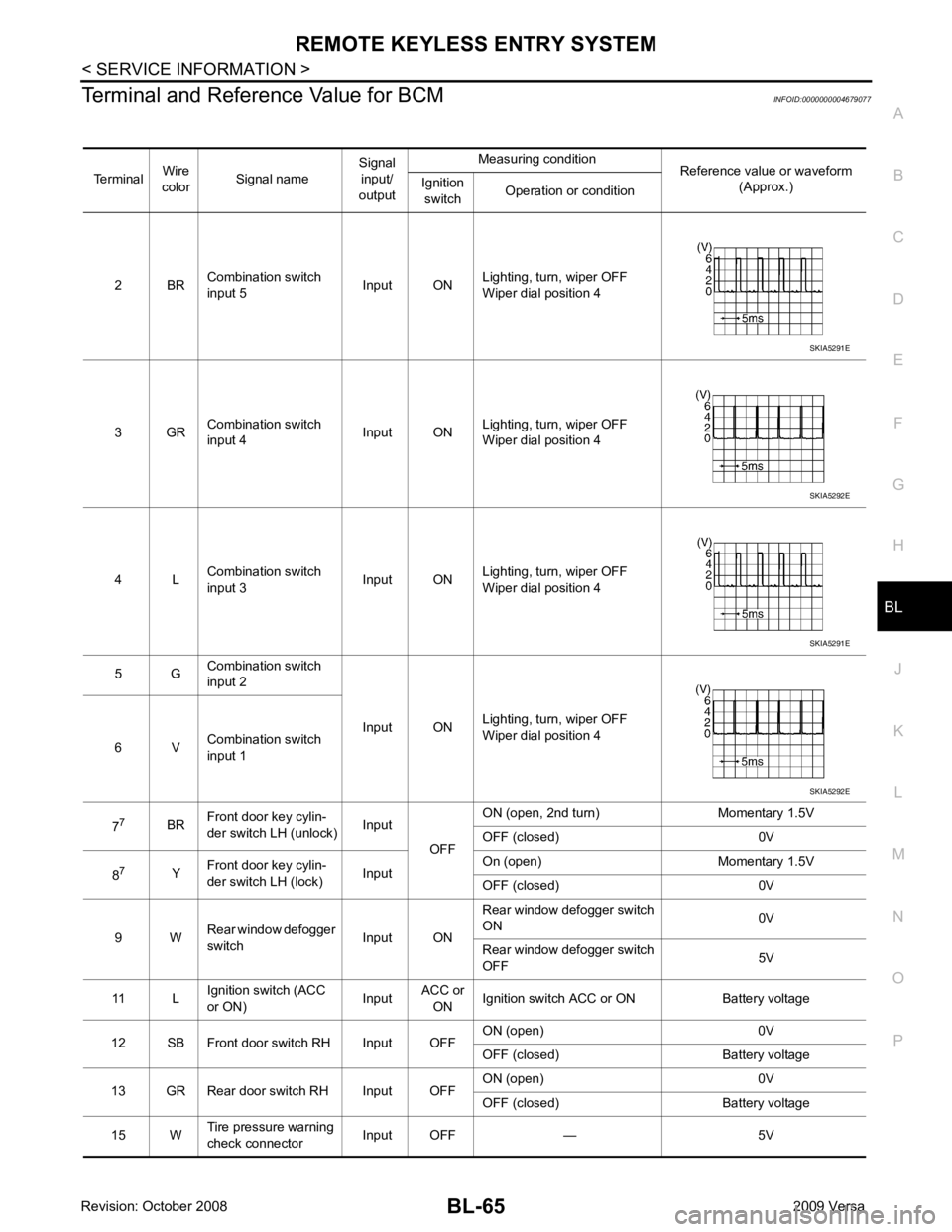
Terminal and Reference Value for BCM
INFOID:0000000004679077
Terminal Wire
color Signal name Signal
input/
output Measuring condition
Reference value or waveform
(Approx.)
Ignition
switch Operation or condition
2 BR Combination switch
input 5 Input ONLighting, turn, wiper OFF
Wiper dial position 4
3 GR Combination switch
input 4 Input ONLighting, turn, wiper OFF
Wiper dial position 4
4 L Combination switch
input 3 Input ONLighting, turn, wiper OFF
Wiper dial position 4
5 G Combination switch
input 2
Input ONLighting, turn, wiper OFF
Wiper dial position 4
6 V Combination switch
input 1
7 7
BRFront door key cylin-
der switch LH (unlock) Input
OFFON (open, 2nd turn) Momentary 1.5V
OFF (closed) 0V
8 7
YFront door key cylin-
der switch LH (lock) InputOn (open) Momentary 1.5V
OFF (closed) 0V
9 W Rear window defogger
switch Input ONRear window defogger switch
ON 0V
Rear window defogger switch
OFF 5V
11 L Ignition switch (ACC
or ON) InputACC or
ON Ignition switch ACC or ON Battery voltage
12 SB Front door switch RH Input OFF ON (open) 0V
OFF (closed) Battery voltage
13 GR Rear door switch RH Input OFF ON (open) 0V
OFF (closed) Battery voltage
15 W Tire pressure warning
check connector Input OFF — 5V SKIA5291E
SKIA5292E
SKIA5291E
SKIA5292E
Page 530 of 4331
BL
N
O P
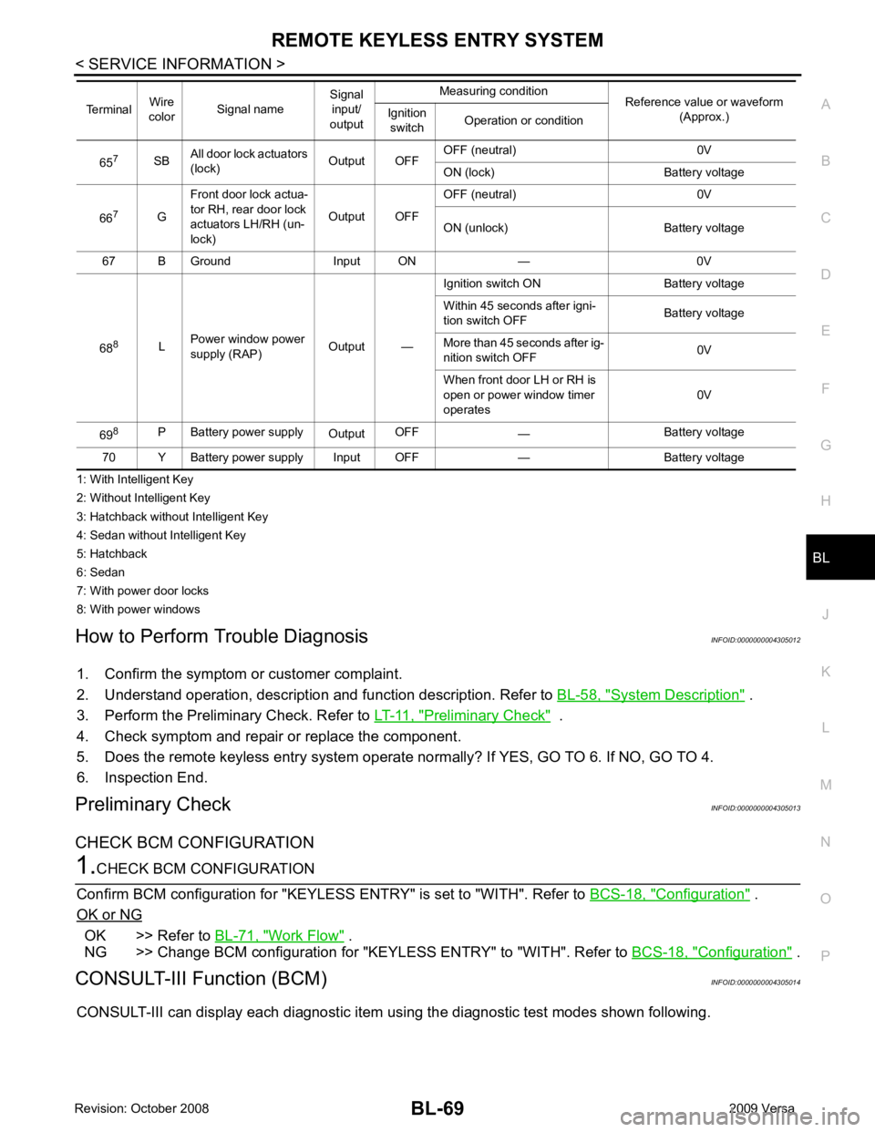
1: With Intelligent Key
2: Without Intelligent Key
3: Hatchback without Intelligent Key
4: Sedan without Intelligent Key
5: Hatchback
6: Sedan
7: With power door locks
8: With power windows
How to Perform Trouble Diagnosis INFOID:0000000004305012
1. Confirm the symptom or customer complaint.
2. Understand operation, description and function description. Refer to BL-58, " System Description " .
3. Perform the Preliminary Check. Refer to LT-11, " Preliminary Check " .
4. Check symptom and repair or replace the component.
5. Does the remote keyless entry system operate normally? If YES, GO TO 6. If NO, GO TO 4.
6. Inspection End.
Preliminary Check INFOID:0000000004305013
CHECK BCM CONFIGURATION Configuration " .
OK or NG OK >> Refer to
BL-71, " Work Flow " .
NG >> Change BCM configuration for "KEYLESS ENTRY" to "WITH". Refer to BCS-18, " Configuration " .
CONSULT-III Function (BCM) INFOID:0000000004305014
CONSULT-III can display each diagnostic item using the diagnostic test modes shown following. 65
7
SBAll door lock actuators
(lock) Output OFFOFF (neutral) 0V
ON (lock) Battery voltage
66 7
GFront door lock actua-
tor RH, rear door lock
actuators LH/RH (un-
lock) Output OFFOFF (neutral) 0V
ON (unlock) Battery voltage
67 B Ground Input ON — 0V
68 8
LPower window power
supply (RAP) Output —Ignition switch ON Battery voltage
Within 45 seconds after igni-
tion switch OFF Battery voltage
More than 45 seconds after ig-
nition switch OFF 0V
When front door LH or RH is
open or power window timer
operates 0V
69 8
P Battery power supply
OutputOFF
— Battery voltage
70 Y Battery power supply Input OFF — Battery voltage
Terminal
Wire
color Signal name Signal
input/
output Measuring condition
Reference value or waveform
(Approx.)
Ignition
switch Operation or condition
Page 556 of 4331
BL
N
O P
CHANGE SETTINGS FUNCTION
The settings for each function c an be changed with the CONSULT-III.
Changing Settings Using CONSULT-III The settings for the Intelligent Key system func tions can be changed using CONSULT-III (WORK SUPPORT).
Refer to BL-117, " CONSULT-III Application Item " .
NOTE:
Once a function setting is changed, it will remain effective even if the battery is disconnected.
INTELLIGENT KEY REGISTRATION Intelligent Key-ID registration is performed using the CONSULT-III.
CAUTION:
• After a new Intelligent Key-ID is regi stered, be sure to check the function.
• When registering an additional Intelligent Key-ID , take any Intelligent Keys already registered and
Intelligent Keys for any other vehicles out of the vehicle before starting.
CONSULT-III can be used to check and delete Intelligent Key-IDs.
For further information, see the CONS ULT-III Operation Manual NATS.
STEERING LOCK SOLENOID REGISTRATION
Steering Lock Solenoid ID Registration CAUTION:
• The method for registering a st eering lock solenoid ID depends on the status of the steering lock
solenoid and Intelligent Key unit (new or old unit).
• After registration is completed, press ignition switch with an Intelligent Key in the vehicle so that it
can be turned, and confirm that it cannot be turn ed even when ignition switch is pressed without an
Intelligent Key in the vehicle.
For further information, see the CONSULT- III Operation Manual NATS-IVIS/NVIS.
CAN Communication System Description INFOID:0000000004305033
Refer to LAN-8 .
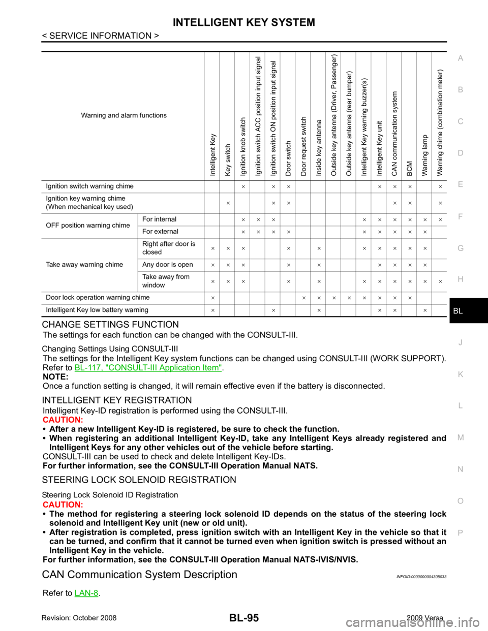
Warning and alarm functionsIntelligent Key
Key switch
Ignition knob switch
Ignition switch ACC position input signal
Ignition switch ON position input signal
Door switch
Door request switch
Inside key antenna
Outside key antenna (Driver, Passenger)
Outside key antenna (rear bumper)
Intelligent Key warning buzzer(s)
Intelligent Key unit
CAN communication system
BCM
Warning lamp
Warning chime (combination meter)
Ignition switch warning chime × × × × × × ×
Ignition key warning chime
(When mechanical key used) × × × × × ×
OFF position warning chime For internal
× × × × × × × × ×
For external × × × × × × × × ×
Take away warning chime Right after door is
closed × × × × × × × × × ×
Any door is open × × × × × × × × ×
Take away from
window × × × × × × × × × × ×
Door lock operation warning chime × × × × × × × × ×
Intelligent Key low battery warning × × × × × ×
Page 572 of 4331
INTELLIGENT KEY SYSTEM
BL-111
< SERVICE INFORMATION >
C
D E
F
G H
J
K L
M A
B BL
N
O P
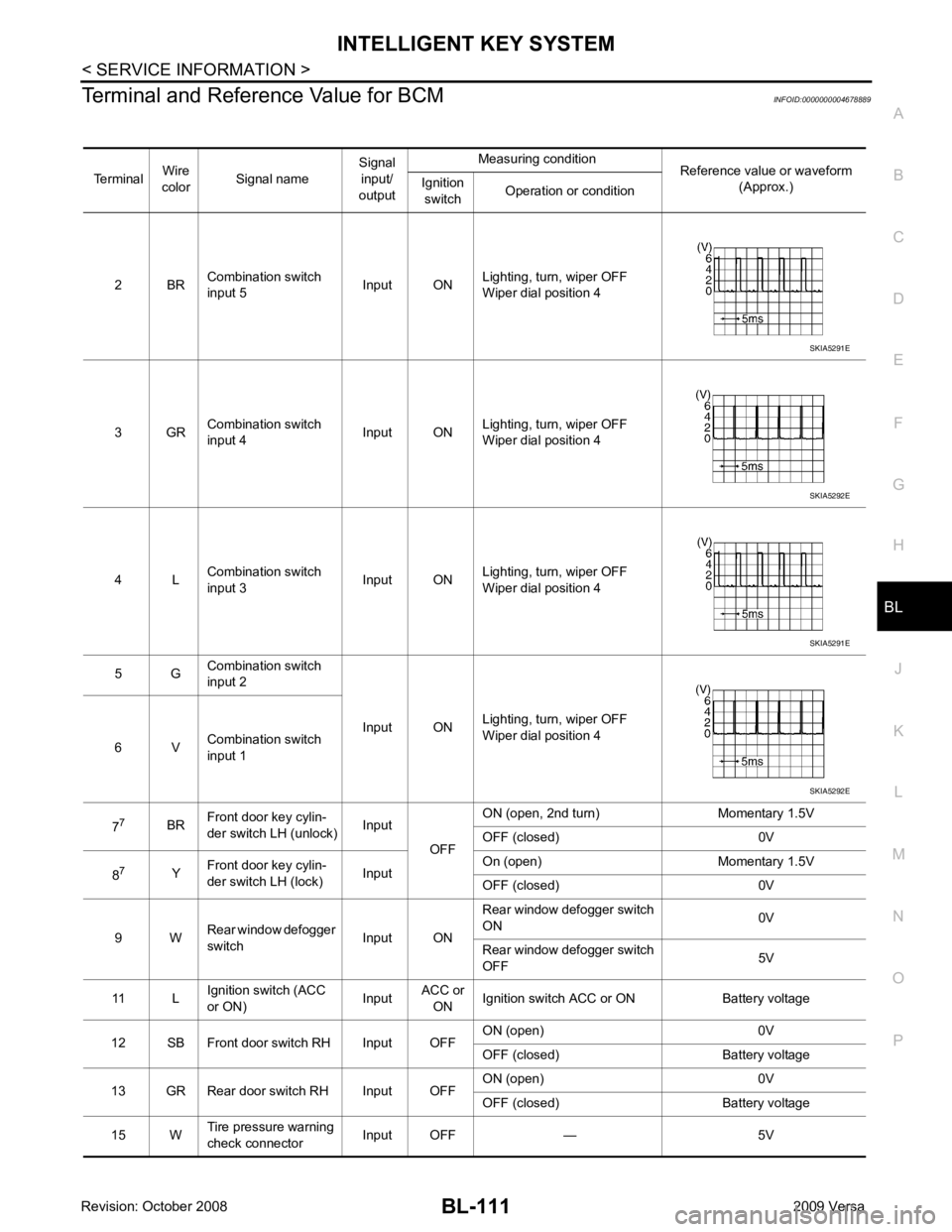
Terminal and Reference Value for BCM
INFOID:0000000004678889
Terminal Wire
color Signal name Signal
input/
output Measuring condition
Reference value or waveform
(Approx.)
Ignition
switch Operation or condition
2 BR Combination switch
input 5 Input ONLighting, turn, wiper OFF
Wiper dial position 4
3 GR Combination switch
input 4 Input ONLighting, turn, wiper OFF
Wiper dial position 4
4 L Combination switch
input 3 Input ONLighting, turn, wiper OFF
Wiper dial position 4
5 G Combination switch
input 2
Input ONLighting, turn, wiper OFF
Wiper dial position 4
6 V Combination switch
input 1
7 7
BRFront door key cylin-
der switch LH (unlock) Input
OFFON (open, 2nd turn) Momentary 1.5V
OFF (closed) 0V
8 7
YFront door key cylin-
der switch LH (lock) InputOn (open) Momentary 1.5V
OFF (closed) 0V
9 W Rear window defogger
switch Input ONRear window defogger switch
ON 0V
Rear window defogger switch
OFF 5V
11 L Ignition switch (ACC
or ON) InputACC or
ON Ignition switch ACC or ON Battery voltage
12 SB Front door switch RH Input OFF ON (open) 0V
OFF (closed) Battery voltage
13 GR Rear door switch RH Input OFF ON (open) 0V
OFF (closed) Battery voltage
15 W Tire pressure warning
check connector Input OFF — 5V SKIA5291E
SKIA5292E
SKIA5291E
SKIA5292E
Page 576 of 4331

BL
N
O P
1: With Intelligent Key
2: Without Intelligent Key
3: Hatchback without Intelligent Key
4: Sedan without Intelligent Key
5: Hatchback
6: Sedan
7: With power door locks
8: With power windows
Trouble Diagnosis Procedure INFOID:0000000004305041
PRELIMINARY CHECK Configuration " .
OK or NG OK >> GO TO 3
NG >> Change BCM configuration for "I-KEY" to "WITH". Refer to BCS-18, " Configuration " .
Intelligent Key Battery Replacement " .
The engine cannot be started by all Intelligent Keys >> GO TO 4 65
7
SBAll door lock actuators
(lock) Output OFFOFF (neutral) 0V
ON (lock) Battery voltage
66 7
GFront door lock actua-
tor RH, rear door lock
actuators LH/RH (un-
lock) Output OFFOFF (neutral) 0V
ON (unlock) Battery voltage
67 B Ground Input ON — 0V
68 8
LPower window power
supply (RAP) Output —Ignition switch ON Battery voltage
Within 45 seconds after igni-
tion switch OFF Battery voltage
More than 45 seconds after ig-
nition switch OFF 0V
When front door LH or RH is
open or power window timer
operates 0V
69 8
P Battery power supply
OutputOFF
— Battery voltage
70 Y Battery power supply Input OFF — Battery voltage
Terminal
Wire
color Signal name Signal
input/
output Measuring condition
Reference value or waveform
(Approx.)
Ignition
switch Operation or condition
Page 580 of 4331

BL
N
O P
Trouble Diagnosis Symptom Chart INFOID:0000000004305044
KEY WARNING LAMP (GREEN) ILLUMINATES NOTE: Monitor item Description
CONFIRM KEY FOB ID It can be checked whether Intelligent Key ID code is registered or not in this mode.
TAKE OUT FROM WINDOW
WARN Take away warning chime (from window) mode can be changed to operate (ON) or not operate
(OFF) with this mode. The operation mode will be changed when “CHANGE SETT” on CONSULT-
III screen is touched.
LOW BAT OF KEY FOB WARN Intelligent Key low battery warning mode can be changed to operate (ON) or not operate (OFF)
with this mode. The operation mode will be changed when “CHANGE SETT” on CONSULT-III
screen is touched.
ANSWER BACK FUNCTION Buzzer reminder function mode by Intelligent button can be changed to operate (ON) or not oper-
ate (OFF) with this mode. The operation mode will be changed when “CHANGE SETT” on CON-
SULT-III screen is touched.
SELECTIVE UNLOCK FUNC-
TION Selective unlock function mode can be changed to operate (ON) or not operate (OFF) with this
mode. The operation mode will be changed when “CHANGE SETT” on CONSULT-III screen is
touched.
ANTI KEY LOCK IN FUNCTION Key reminder function mode can be changed to operate (ON) or not operate (OFF) with this mode.
The operation mode will be changed when “CHANGE SETT” on CONSULT-III screen is touched.
HORN WITH KEYLESS LOCK Horn reminder function mode by Intelligent Key remote control button can be changed to operate
(ON) or not operate (OFF) with this mode. The operation mode will be changed when “CHANGE
SETT” on CONSULT-III screen is touched.
HAZARD ANSWER BACK Hazard reminder function mode can be selected from the following with this mode. The operation
mode will be changed when “CHANGE SE TT” on CONSULT-III screen is touched.
• LOCK ONLY: Door lock operation only
• UNLOCK ONLY: Door unlock operation only
• LOCK/UNLOCK: Lock/Unlock operation
• OFF: Non-operation
ANSWER BACK WITH I-KEY
LOCK Buzzer reminder function (lock operation) mode by door request switch (driver side, passenger
side and back door side) can be selected from the following with this mode. The operation mode
will be changed when “ CHANGE SETT” on CONSULT- III screen is touched.
• BUZZER: Sound buzzer
• OFF: Non-operation
ANSWER BACK WITH I-KEY UN-
LOCK Buzzer reminder function (unlock operation) mode by door request switch can be changed to op-
erate (ON) or not operate (OFF) with this mode.
AUTO RELOCK TIMER Auto door lock timer mode can select the following with this mode.
• 1 minute
• OFF: Non-operation
PANIC ALARM DELAY Panic alarm button's pressing time on Intelligent Key remote control button can be selected from
the following with this mode. The operation mode will be changed when “CHANGE SETT” on
CONSULT-III screen is touched.
• 0.5 second
• 1.5 second
• OFF: Non-operation
P/W DOWN DELAY Unlock button's pressing time on Intelligent Key remote control button can be selected from the
following with this mode. The operation mode will be changed when “CHANGE SETT” on CON-
SULT-III screen is touched.
• 3 seconds
• 5 seconds
• OFF: Non-operation
ENGINE START BY I-KEY Engine start function mode can be changed to operate (ON) or not operate (OFF) with this mode.
The operation mode will be changed when “CHANGE SETT” on CONSULT-III screen is touched.
LOCK/UNLOCK BY I-KEY Door lock/unlock function by door request switch (driver side, passenger side and back door side)
mode can be changed to operate (ON) or not operate (OFF) with this mode. The operation mode
will be changed when “ CHANGE SETT” on CONSULT- III screen is touched.
Page 586 of 4331
BL
N
O P
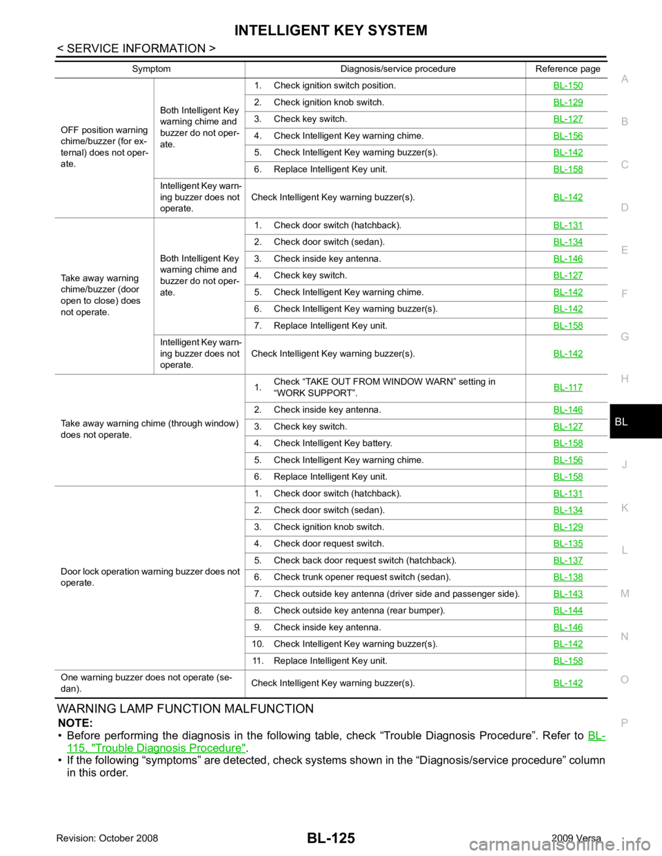
WARNING LAMP FUNCTION MALFUNCTION
NOTE:
• Before performing the diagnosis in the following table, check “Trouble Diagnosis Procedure”. Refer to BL-115, " Trouble Diagnosis Procedure " .
• If the following “symptoms” are detected, check syst ems shown in the “Diagnosis/service procedure” column
in this order.
OFF position warning
chime/buzzer (for ex-
ternal) does not oper-
ate. Both Intelligent Key
warning chime and
buzzer do not oper-
ate. 1. Check ignition switch position.
BL-1502. Check ignition knob switch.
BL-1293. Check key switch.
BL-1274. Check Intelligent Key warning chime.
BL-1565. Check Intelligent Ke
y warning buzzer(s). BL-142 6. Replace Intelligent Key unit.
BL-158Intelligent Key warn-
ing buzzer does not
operate. Check Intelligent Key warning buzzer(s).
BL-142Take away warning
chime/buzzer (door
open to close) does
not operate. Both Intelligent Key
warning chime and
buzzer do not oper-
ate. 1. Check door switch (hatchback).
BL-1312. Check door switch (sedan).
BL-1343. Check inside key antenna.
BL-1464. Check key switch.
BL-1275. Check Intelligent Key warning chime.
BL-1426. Check Intelligent Ke
y warning buzzer(s). BL-142 7. Replace Intelligent Key unit.
BL-158Intelligent Key warn-
ing buzzer does not
operate. Check Intelligent Key warning buzzer(s).
BL-142Take away warning chime (through window)
does not operate. 1.
Check “TAKE OUT FROM WINDOW WARN” setting in
“WORK SUPPORT”. BL-1172. Check inside key antenna.
BL-1463. Check key switch.
BL-1274. Check Intelligent Key battery.
BL-1585. Check Intelligent Key warning chime.
BL-1566. Replace Intelligent Key unit.
BL-158Door lock operation warning buzzer does not
operate. 1. Check door switch (hatchback).
BL-1312. Check door switch (sedan).
BL-1343. Check ignition knob switch.
BL-1294. Check door request switch.
BL-1355. Check back door request switch (hatchback).
BL-1376. Check trunk opener request switch (sedan).
BL-1387. Check outside key antenna (driver side and passenger side).
BL-1438. Check outside key antenna (rear bumper).
BL-1449. Check inside key antenna.
BL-14610. Check Intelligent Key warning buzzer(s).
BL-14211. Replace Intelligent Key unit.
BL-158One warning buzzer does not operate (se-
dan). Check Intelligent Key warning buzzer(s).
BL-142Symptom Diagnosis/service procedure Reference page
Page 627 of 4331
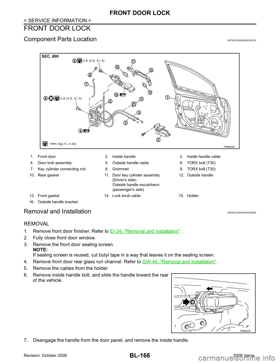
Removal and Installation " .
2. Fully close front door window.
3. Remove the front door sealing screen. NOTE:
If sealing screen is reused, cut butyl tape in a way that leaves it on the sealing screen.
4. Remove front door rear glass run channel. Refer to GW-44, " Removal and Installation " .
5. Remove the cables from the holder.
6. Remove inside handle bolt, and slide the handle toward the rear of the vehicle.
7. Disengage the handle from the door panel, and remove the inside handle. 1. Front door 2. Inside handle 3. Inside handle cable
4. Door lock assembly 5. Outside handle cable 6. TORX bolt (T30)
7. Key cylinder connecting rod 8. Grommet 9. TORX bolt (T30)
10. Rear gasket 11. Door key cylinder assembly (Driver's side)
Outside handle escutcheon
(passenger's side) 12. Outside handle
13. Front gasket 14. Lock knob cable 15. Holder
16. Outside handle bracket PIIB6524E
Page 630 of 4331
BL
N
O P
REAR DOOR LOCK
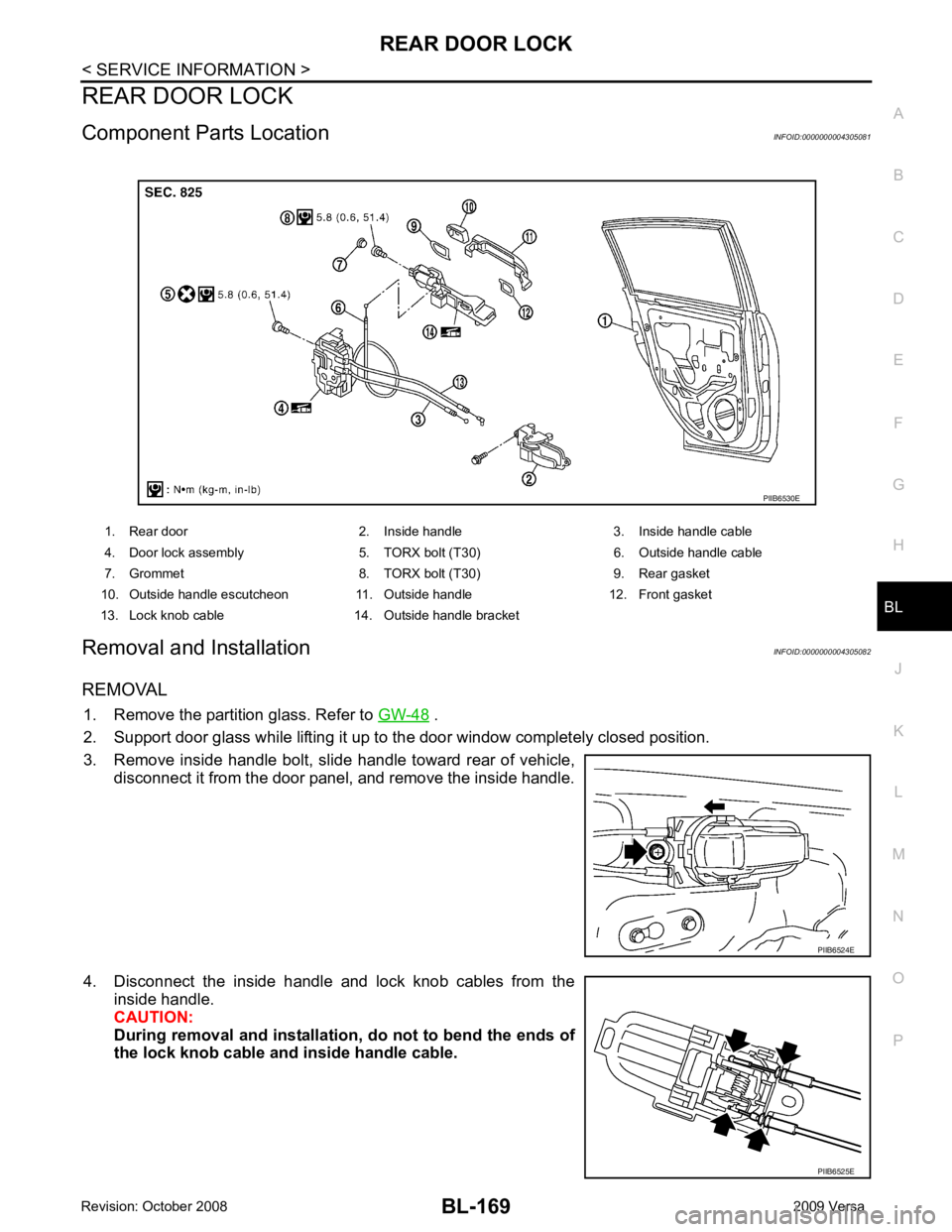
Component Parts Location INFOID:0000000004305081
Removal and Installation INFOID:0000000004305082
REMOVAL 1. Remove the partition glass. Refer to GW-48 .
2. Support door glass while lifting it up to the door window completely closed position.
3. Remove inside handle bolt, slide handle toward rear of vehicle, disconnect it from the door panel, and remove the inside handle.
4. Disconnect the inside handle and lock knob cables from the inside handle.
CAUTION:
During removal and installation, do not to bend the ends of
the lock knob cable and inside handle cable.
1. Rear door 2. Inside handle 3. Inside handle cable
4. Door lock assembly 5. TORX bolt (T30) 6. Outside handle cable
7. Grommet 8. TORX bolt (T30) 9. Rear gasket
10. Outside handle escutcheon 11. Outside handle 12. Front gasket
13. Lock knob cable 14. Outside handle bracket PIIB6525E
Page 636 of 4331
BACK DOOR LOCK
BL-175
< SERVICE INFORMATION >
C
D E
F
G H
J
K L
M A
B BL
N
O P
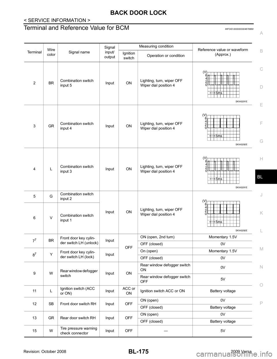
Terminal and Reference Value for BCM
INFOID:0000000004678868
Terminal Wire
color Signal name Signal
input/
output Measuring condition
Reference value or waveform
(Approx.)
Ignition
switch Operation or condition
2 BR Combination switch
input 5 Input ONLighting, turn, wiper OFF
Wiper dial position 4
3 GR Combination switch
input 4 Input ONLighting, turn, wiper OFF
Wiper dial position 4
4 L Combination switch
input 3 Input ONLighting, turn, wiper OFF
Wiper dial position 4
5 G Combination switch
input 2
Input ONLighting, turn, wiper OFF
Wiper dial position 4
6 V Combination switch
input 1
7 7
BRFront door key cylin-
der switch LH (unlock) Input
OFFON (open, 2nd turn) Momentary 1.5V
OFF (closed) 0V
8 7
YFront door key cylin-
der switch LH (lock) InputOn (open) Momentary 1.5V
OFF (closed) 0V
9 W Rear window defogger
switch Input ONRear window defogger switch
ON 0V
Rear window defogger switch
OFF 5V
11 L Ignition switch (ACC
or ON) InputACC or
ON Ignition switch ACC or ON Battery voltage
12 SB Front door switch RH Input OFF ON (open) 0V
OFF (closed) Battery voltage
13 GR Rear door switch RH Input OFF ON (open) 0V
OFF (closed) Battery voltage
15 W Tire pressure warning
check connector Input OFF — 5V SKIA5291E
SKIA5292E
SKIA5291E
SKIA5292E