diagram NISSAN TIIDA 2009 Service Owner's Manual
[x] Cancel search | Manufacturer: NISSAN, Model Year: 2009, Model line: TIIDA, Model: NISSAN TIIDA 2009Pages: 4331, PDF Size: 58.04 MB
Page 136 of 4331
DTC P0744 A/T TCC S/
V FUNCTION (LOCK-UP)
AT-131
< SERVICE INFORMATION >
D
E
F
G H
I
J
K L
M A
B AT
N
O P
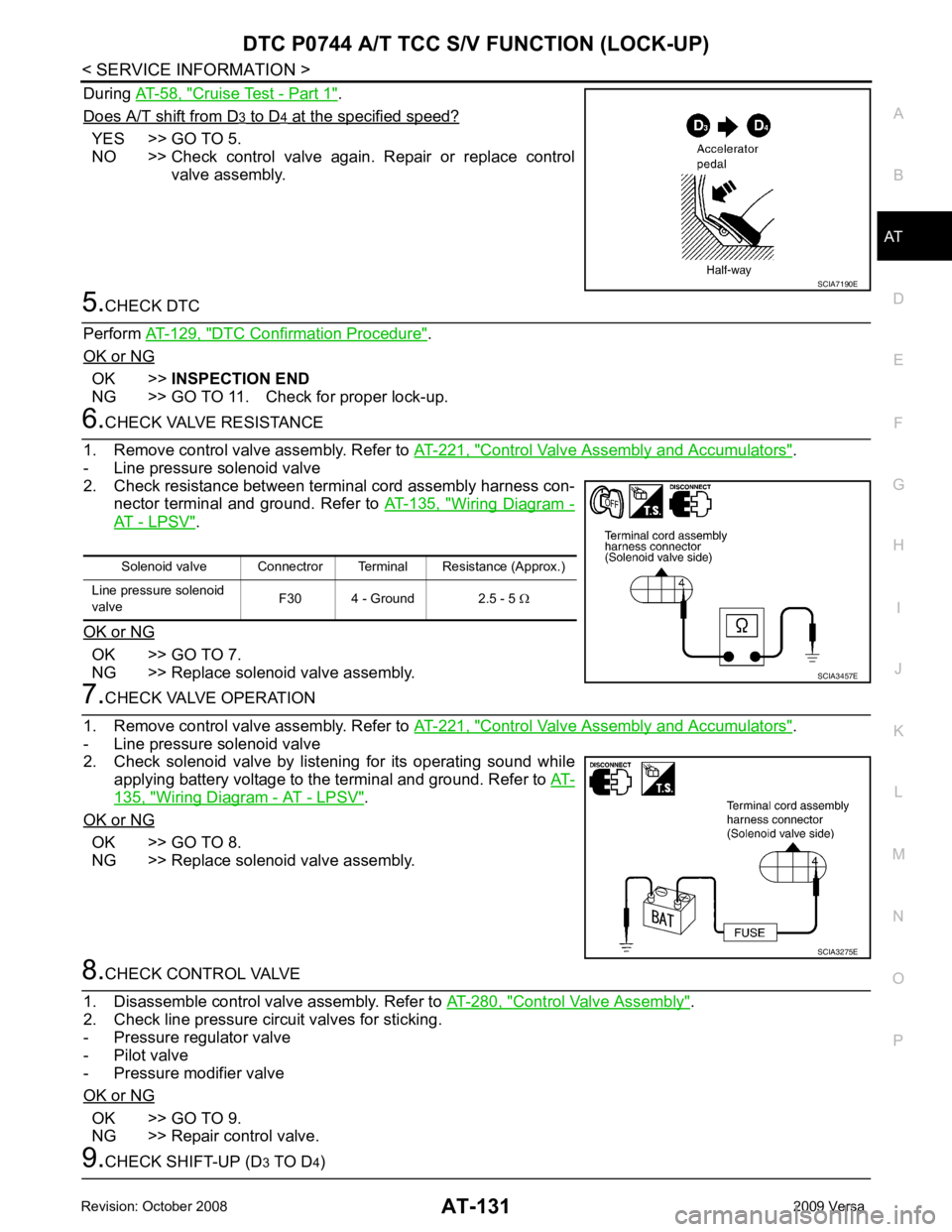
During
AT-58, " Cruise Test - Part 1 " .
Does A/T shift from D 3 to D 4 at the specified speed?
YES >> GO TO 5.
NO >> Check control valve again. Repair or replace control valve assembly. 5.
CHECK DTC
Perform AT-129, " DTC Confirmation Procedure " .
OK or NG OK >>
INSPECTION END
NG >> GO TO 11. Check for proper lock-up. 6.
CHECK VALVE RESISTANCE
1. Remove control valve assembly. Refer to AT-221, " Control Valve Assembly and Accumulators " .
- Line pressure solenoid valve
2. Check resistance between terminal cord assembly harness con- nector terminal and ground. Refer to AT-135, " Wiring Diagram -
AT - LPSV " .
OK or NG OK >> GO TO 7.
NG >> Replace solenoid valve assembly. 7.
CHECK VALVE OPERATION
1. Remove control valve assembly. Refer to AT-221, " Control Valve Assembly and Accumulators " .
- Line pressure solenoid valve
2. Check solenoid valve by listening for its operating sound while
applying battery voltage to the terminal and ground. Refer to AT-135, " Wiring Diagram - AT - LPSV " .
OK or NG OK >> GO TO 8.
NG >> Replace solenoid valve assembly. 8.
CHECK CONTROL VALVE
1. Disassemble control valve assembly. Refer to AT-280, " Control Valve Assembly " .
2. Check line pressure circuit valves for sticking.
- Pressure regulator valve
- Pilot valve
- Pressure modifier valve
OK or NG OK >> GO TO 9.
NG >> Repair control valve. 9.
CHECK SHIFT-UP (D 3 TO D 4) SCIA7190E
Solenoid valve Connectror Terminal Resistance (Approx.)
Line pressure solenoid
valve F30 4 - Ground 2.5 - 5
Ω SCIA3457E
SCIA3275E
Page 137 of 4331
AT-132< SERVICE INFORMATION >
DTC P0744 A/T TCC S/V FUNCTION (LOCK-UP)
During AT-58, " Cruise Test - Part 1 " .
Does A/T shift from D 3 to D 4 at the specified speed?
YES >> GO TO 10.
NO >> Check control valve again. Repair or replace control valve assembly. 10.
CHECK DTC
Perform AT-129, " DTC Confirmation Procedure " .
OK or NG OK >>
INSPECTION END
NG >> GO TO 11. Check for proper lock-up. 11.
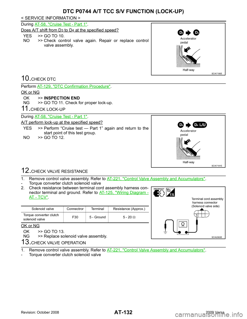
CHECK LOCK-UP
During AT-58, " Cruise Test - Part 1 " .
A/T perform lock-up at the specified speed? YES >> Perform “Cruise test — Part 1” again and return to the
start point of this test group.
NO >> GO TO 12. 12.
CHECK VALVE RESISTANCE
1. Remove control valve assembly. Refer to AT-221, " Control Valve Assembly and Accumulators " .
- Torque converter clutch solenoid valve
2. Check resistance between terminal cord assembly harness con-
nector terminal and ground. Refer to AT-125, " Wiring Diagram -
AT - TCV " .
OK or NG OK >> GO TO 13.
NG >> Replace solenoid valve assembly. 13.
CHECK VALVE OPERATION
1. Remove control valve assembly. Refer to AT-221, " Control Valve Assembly and Accumulators " .
- Torque converter clutch solenoid valve SCIA7190E
SCIA7191E
Solenoid valve Connectror Terminal Resistance (Approx.)
Torque converter clutch
solenoid valve F30 5 - Ground 5 - 20
Ω SCIA2063E
Page 138 of 4331
DTC P0744 A/T TCC S/
V FUNCTION (LOCK-UP)
AT-133
< SERVICE INFORMATION >
D
E
F
G H
I
J
K L
M A
B AT
N
O P
2. Check solenoid valve by listening for its operating sound while
applying battery voltage to the terminal and ground. Refer to AT-125, " Wiring Diagram - AT - TCV " .
OK or NG OK >> GO TO 14.
NG >> Replace solenoid valve assembly. 14.
CHECK CONTROL VALVE
1. Disassemble control valve assembly. Refer to AT-280, " Control Valve Assembly " .
2. Check control valves for sticking.
- Torque converter clutch control valve
- Torque converter clutch relief valve
OK or NG OK >> GO TO 15.
NG >> Repair control valve. 15.
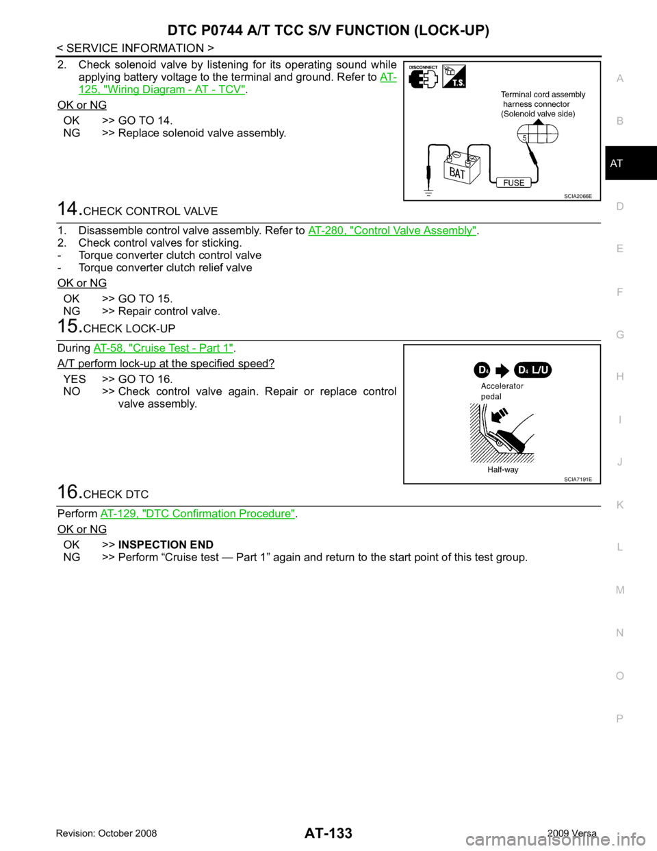
CHECK LOCK-UP
During AT-58, " Cruise Test - Part 1 " .
A/T perform lock-up at the specified speed? YES >> GO TO 16.
NO >> Check control valve again. Repair or replace control
valve assembly. 16.
CHECK DTC
Perform AT-129, " DTC Confirmation Procedure " .
OK or NG OK >>
INSPECTION END
NG >> Perform “Cruise test — Part 1” again and re turn to the start point of this test group. SCIA2066E
SCIA7191E
Page 140 of 4331
AT
N
O P
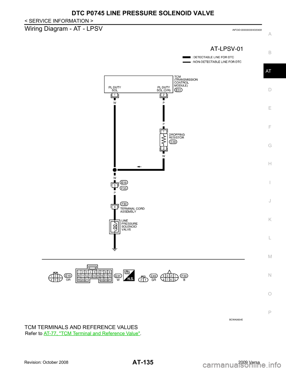
Wiring Diagram - AT - LPSV
INFOID:0000000004305408
TCM TERMINALS AND REFERENCE VALUES Refer to AT-77, " TCM Terminal and Reference Value " .
Page 150 of 4331
AT
N
O P
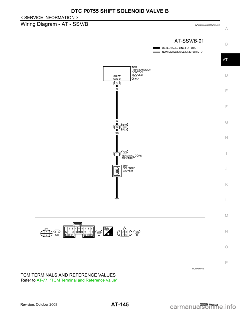
Wiring Diagram - AT - SSV/B
INFOID:0000000004305424
TCM TERMINALS AND REFERENCE VALUES Refer to AT-77, " TCM Terminal and Reference Value " .
Page 160 of 4331
AT
N
O P
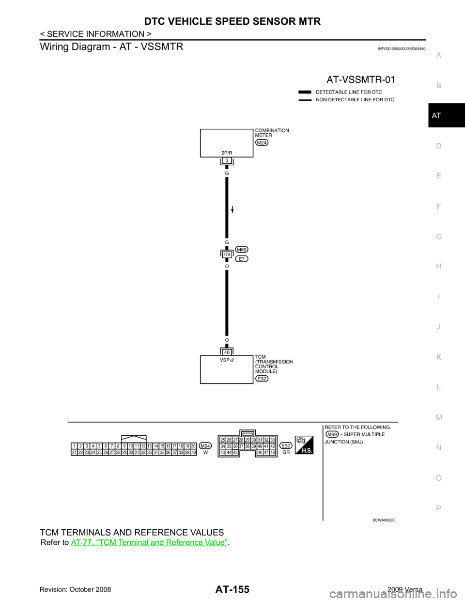
Wiring Diagram - AT - VSSMTR
INFOID:0000000004305440
TCM TERMINALS AND REFERENCE VALUES Refer to AT-77, " TCM Terminal and Reference Value " .
Page 165 of 4331
AT-160< SERVICE INFORMATION >
DTC BATT/FLUID TEMP SEN (A/T FLU
ID TEMP SENSOR CIRCUIT AND TCM
POWER SOURCE)
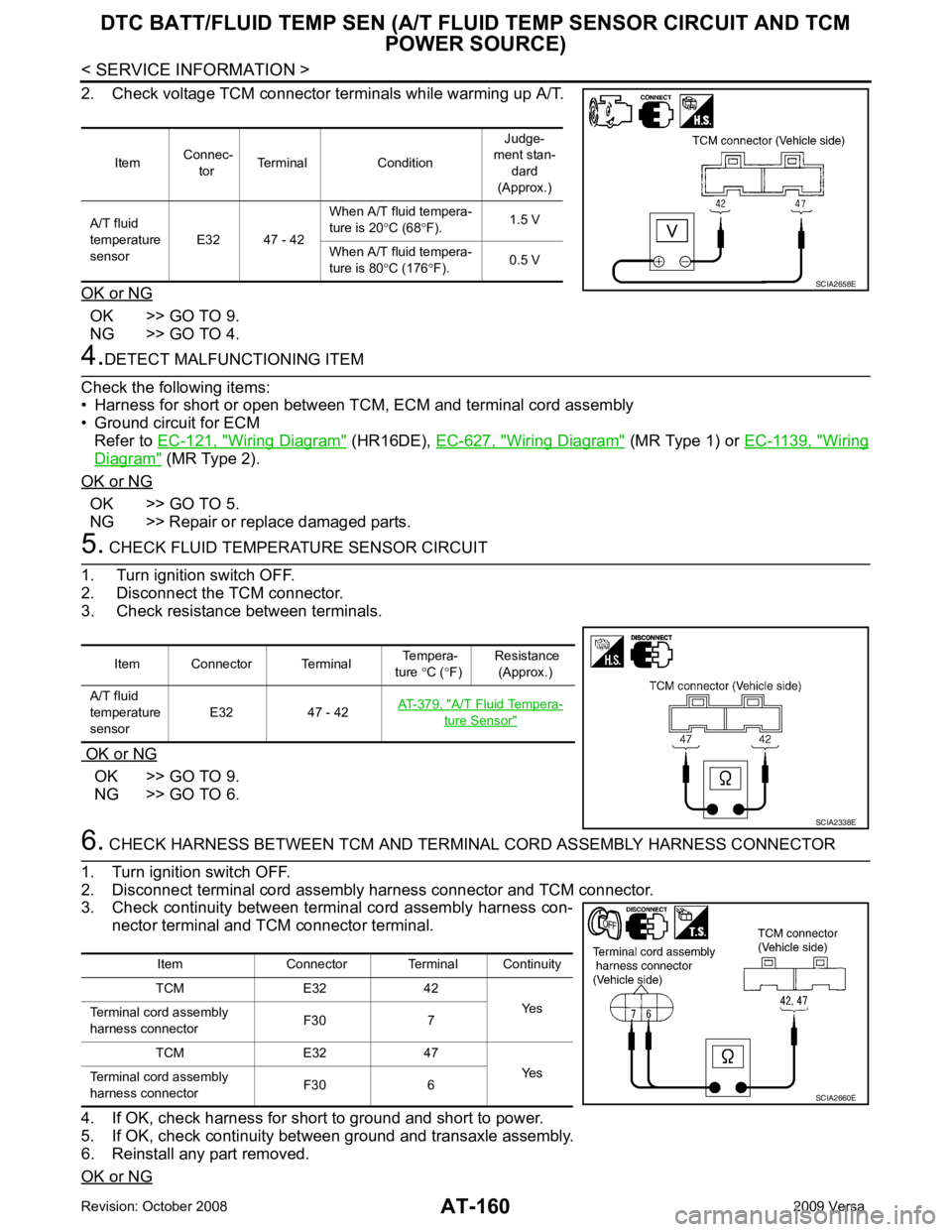
2. Check voltage TCM connector terminals while warming up A/T.
OK or NG OK >> GO TO 9.
NG >> GO TO 4. 4.
DETECT MALFUNCTIONING ITEM
Check the following items:
• Harness for short or open between TCM, ECM and terminal cord assembly
• Ground circuit for ECM
Refer to EC-121, " Wiring Diagram " (HR16DE),
EC-627, " Wiring Diagram " (MR Type 1) or
EC-1139, " Wiring
Diagram " (MR Type 2).
OK or NG OK >> GO TO 5.
NG >> Repair or replace damaged parts. 5.
CHECK FLUID TEMPERATURE SENSOR CIRCUIT
1. Turn ignition switch OFF.
2. Disconnect the TCM connector.
3. Check resistance between terminals.
OK or NG OK >> GO TO 9.
NG >> GO TO 6. 6.
CHECK HARNESS BETWEEN TCM AND TERM INAL CORD ASSEMBLY HARNESS CONNECTOR
1. Turn ignition switch OFF.
2. Disconnect terminal cord assembly harness connector and TCM connector.
3. Check continuity between terminal cord assembly harness con-
nector terminal and TCM connector terminal.
4. If OK, check harness for short to ground and short to power.
5. If OK, check continuity bet ween ground and transaxle assembly.
6. Reinstall any part removed.
OK or NG Item
Connec-
tor Terminal Condition Judge-
ment stan-
dard
(Approx.)
A/T fluid
temperature
sensor E32 47 - 42 When A/T fluid tempera-
ture is 20 °C (68 °F). 1.5 V
When A/T fluid tempera-
ture is 80 °C (176 °F). 0.5 V SCIA2658E
Item Connector Terminal
Tempera-
ture °C ( °F) Resistance
(Approx.)
A/T fluid
temperature
sensor E32 47 - 42
AT-379, " A/T Fluid Tempera-
ture Sensor "
SCIA2338E
Item Connector Terminal Continuity
TCM E32 42 Yes
Terminal cord assembly
harness connector F30 7
TCM E32 47 Yes
Terminal cord assembly
harness connector F30 6 SCIA2660E
Page 170 of 4331
AT
N
O P
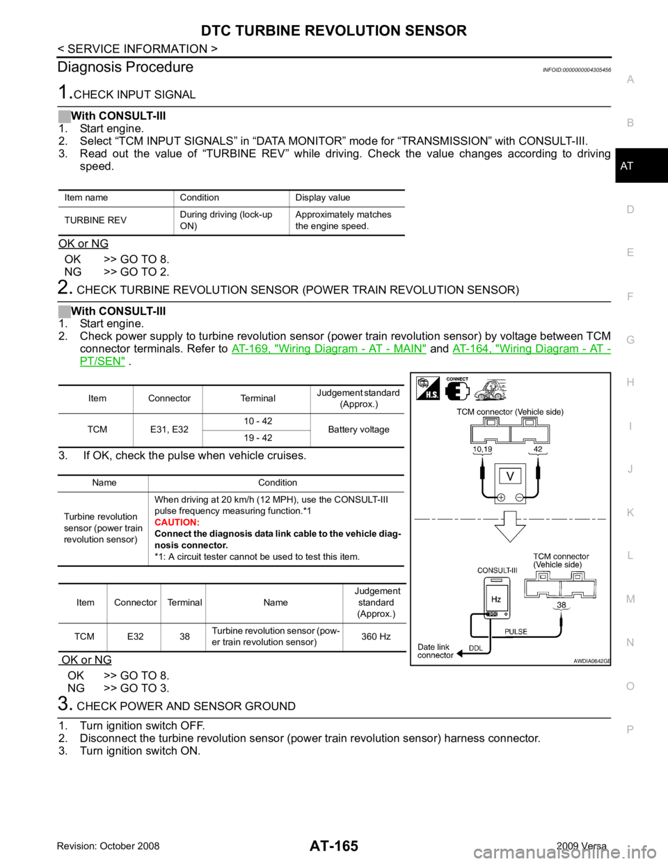
Diagnosis Procedure
INFOID:0000000004305456OK >> GO TO 8.
NG >> GO TO 2. Wiring Diagram - AT - MAIN " and
AT-164, " Wiring Diagram - AT -
PT/SEN " .
3. If OK, check the pulse when vehicle cruises.
OK or NG OK >> GO TO 8.
NG >> GO TO 3. Item Connector Terminal
Judgement standard
(Approx.)
TCM E31, E32 10 - 42
Battery voltage
19 - 42
Name Condition
Turbine revolution
sensor (power train
revolution sensor) When driving at 20 km/h (12 MPH), use the CONSULT-III
pulse frequency measuring function.*1
CAUTION:
Connect the diagnosis data link cable to the vehicle diag-
nosis connector.
*1: A circuit tester cannot be used to test this item.
Item Connector Terminal Name Judgement
standard
(Approx.)
TCM E32 38 Turbine revolution sensor (pow-
er train revolution sensor) 360 Hz B
Page 172 of 4331
AT
N
O P
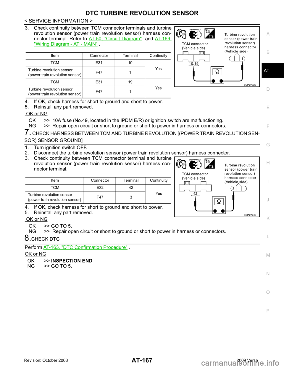
3. Check continuity between TCM connector terminals and turbine
revolution sensor (power train revolution sensor) harness con-
nector terminal. Refer to AT-50, " Circuit Diagram " and
AT-169, " Wiring Diagram - AT - MAIN " .
4. If OK, check harness for short to ground and short to power.
5. Reinstall any part removed.
OK or NG OK >> 10A fuse (No.49, located in the IPDM
E/R) or ignition switch are malfunctioning.
NG >> Repair open circuit or short to ground or short to power in harness or connectors.
7. CHECK HARNESS BETWEEN TCM AND TURBINE R EVOLUTION [(POWER TRAIN REVOLUTION SEN- OK >> GO TO 5.
NG >> Repair open circuit or short to ground or short to power in harness or connectors. DTC Confirmation Procedure " .
OK or NG OK >>
INSPECTION END
NG >> GO TO 5. Item Connector Terminal Continuity
TCM E31 10 Yes
Turbine revolu tion sensor
(power train revolution sensor) F47 1
TCM E31 19 Yes
Turbine revolu tion sensor
(power train revolution sensor) F47 1
Page 174 of 4331
AT
N
O P
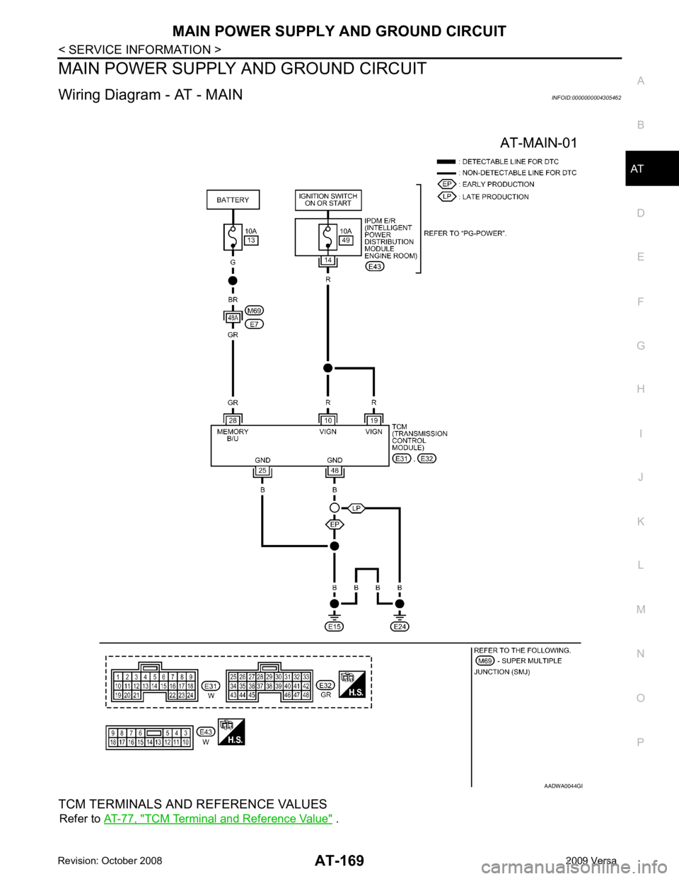
MAIN POWER SUPPLY AND GROUND CIRCUIT
Wiring Diagram - AT - MAIN INFOID:0000000004305462
TCM TERMINALS AND REFERENCE VALUES Refer to AT-77, " TCM Terminal and Reference Value " . B