engine overheat NISSAN TIIDA 2009 Service Owner's Manual
[x] Cancel search | Manufacturer: NISSAN, Model Year: 2009, Model line: TIIDA, Model: NISSAN TIIDA 2009Pages: 4331, PDF Size: 58.04 MB
Page 2453 of 4331
EC
NP
O
1 - 6: The numbers refer to the order of inspection.
(continued on next table)
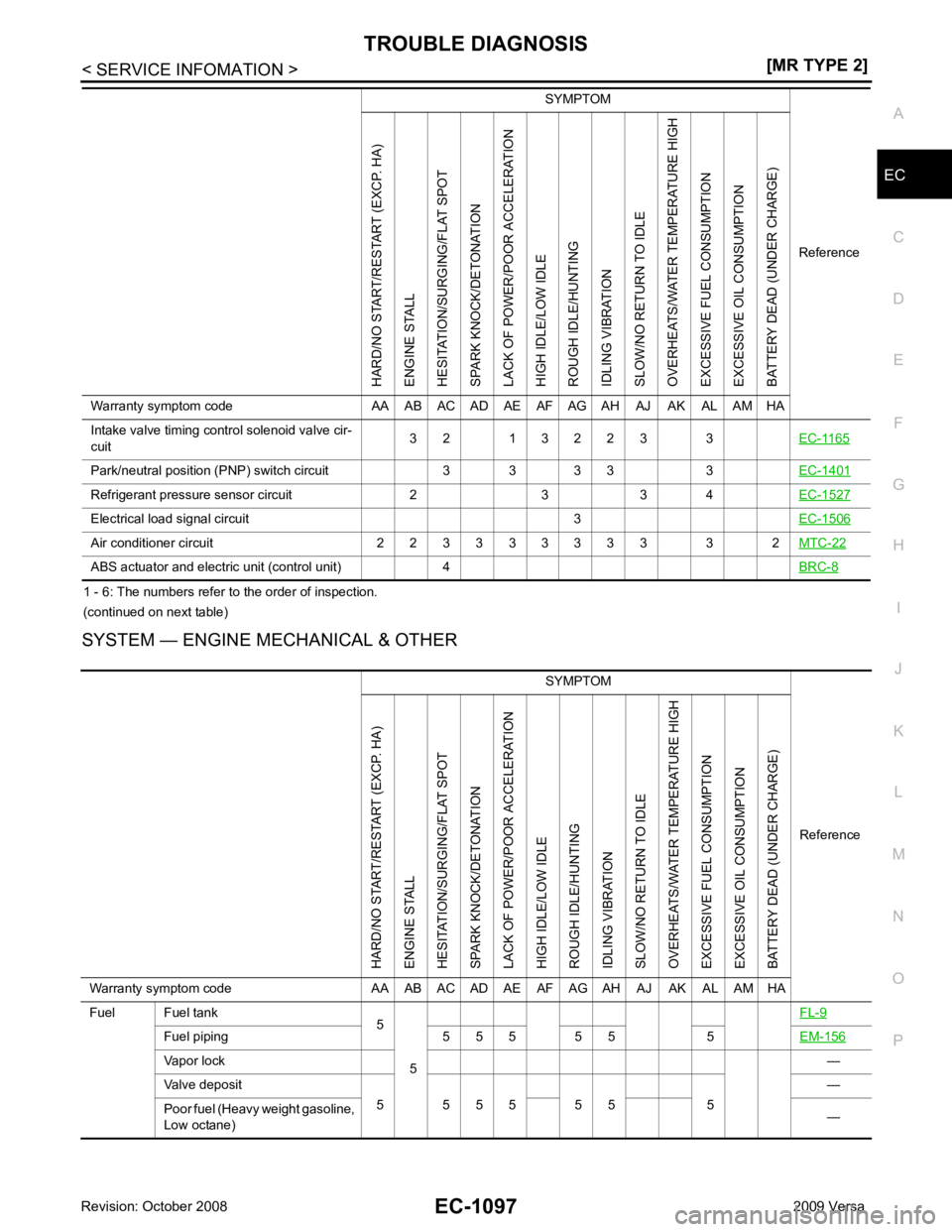
SYSTEM — ENGINE MECHANICAL & OTHER Intake valve timing control solenoid valve cir-
cuit 3 2 1 3 2 2 3 3
EC-1165Park/neutral position (P
NP) switch circuit 3 3 3 3 3 EC-1401Refrigerant pressure sensor circuit 2 3 3 4
EC-1527Electrical load signal circuit 3
EC-1506Air conditioner circuit 2 2 3 3 3 3 3 3 3 3 2
MTC-22ABS actuator and electric unit (control unit) 4
BRC-8SYMPTOM
ReferenceHARD/NO START/RESTART (EXCP. HA)
ENGINE STALL
HESITATION/SURGING/FLAT SPOT
SPARK KNOCK/DETONATION
LACK OF POWER/POOR ACCELERATION
HIGH IDLE/LOW IDLE
ROUGH IDLE/HUNTING
IDLING VIBRATION
SLOW/NO RETURN TO IDLE
OVERHEATS/WATER TEMPERATURE HIGH
EXCESSIVE FUEL CONSUMPTION
EXCESSIVE OIL CONSUMPTION
BATTERY DEAD (UNDER CHARGE)
Warranty symptom code AA AB AC AD AE AF AG AH AJ AK AL AM HA SYMPTOM
Reference
HARD/NO START/RESTART (EXCP. HA)
ENGINE STALL
HESITATION/SURGING/FLAT SPOT
SPARK KNOCK/DETONATION
LACK OF POWER/POOR ACCELERATION
HIGH IDLE/LOW IDLE
ROUGH IDLE/HUNTING
IDLING VIBRATION
SLOW/NO RETURN TO IDLE
OVERHEATS/WATER TEMPERATURE HIGH
EXCESSIVE FUEL CONSUMPTION
EXCESSIVE OIL CONSUMPTION
BATTERY DEAD (UNDER CHARGE)
Warranty symptom code AA AB AC AD AE AF AG AH AJ AK AL AM HA
Fuel Fuel tank 5
5 FL-9Fuel piping 5 5 5 5 5 5
EM-156Vapor lock
—
Valve deposit 5 5 5 5 5 5 5 —
Poor fuel (Heavy weight gasoline,
Low octane) —
Page 2454 of 4331
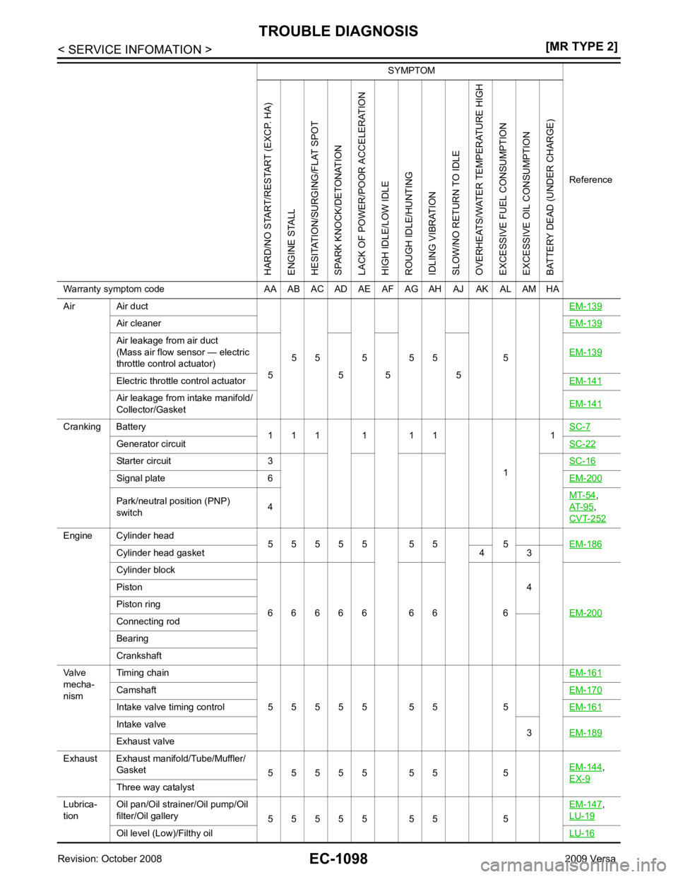
Air cleaner
EM-139Air leakage from air duct
(Mass air flow sensor — electric
throttle control actuator) 5 5 5 5 EM-139Electric throttle control actuator
EM-141Air leakage from intake manifold/
Collector/Gasket EM-141Cranking Battery
1 1 1 1 1 1
11
SC-7 Generator circuit
SC-22Starter circuit 3
SC-16Signal plate 6
EM-200Park/neutral position (PNP)
switch 4 MT-54 ,
AT-95 ,
CVT-252 Engine Cylinder head
5 5 5 5 5 5 5 5 EM-186Cylinder head gasket 4 3
Cylinder block
6 6 6 6 6 6 6 6 4
EM-200 Piston
Piston ring
Connecting rod
Bearing
Crankshaft
Valve
mecha-
nism Timing chain
5 5 5 5 5 5 5 5 EM-161Camshaft
EM-170Intake valve timing control
EM-161Intake valve
3EM-189 Exhaust valve
Exhaust Exhaust manifold/Tube/Muffler/ Gasket 5 5 5 5 5 5 5 5 EM-144 ,
EX-9 Three way catalyst
Lubrica-
tion Oil pan/Oil strainer/Oil pump/Oil
filter/Oil gallery 5 5 5 5 5 5 5 5 EM-147 ,
LU-19 Oil level (Low)/Filthy oil
LU-16SYMPTOM
ReferenceHARD/NO START/RESTART (EXCP. HA)
ENGINE STALL
HESITATION/SURGING/FLAT SPOT
SPARK KNOCK/DETONATION
LACK OF POWER/POOR ACCELERATION
HIGH IDLE/LOW IDLE
ROUGH IDLE/HUNTING
IDLING VIBRATION
SLOW/NO RETURN TO IDLE
OVERHEATS/WATER TEMPERATURE HIGH
EXCESSIVE FUEL CONSUMPTION
EXCESSIVE OIL CONSUMPTION
BATTERY DEAD (UNDER CHARGE)
Warranty symptom code AA AB AC AD AE AF AG AH AJ AK AL AM HA
Page 2455 of 4331
EC
NP
O
1 - 6: The numbers refer to the order of inspection.
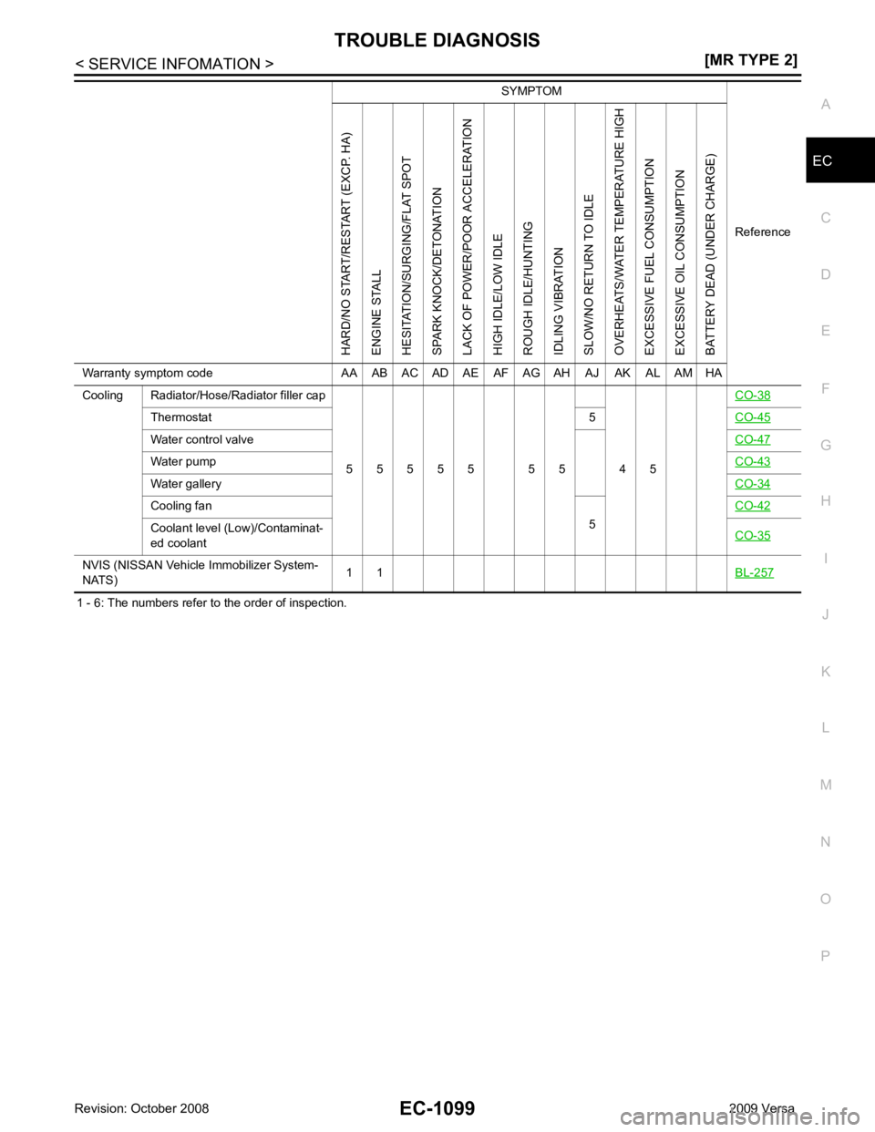
Cooling Radiator/Hose/Radiator filler cap
5 5 5 5 5 5 5 4 5 CO-38Thermostat
5CO-45 Water control valve
CO-47Water pump
CO-43Water gallery
CO-34Cooling fan
5CO-42 Coolant level (Low)/Contaminat-
ed coolant CO-35NVIS (NISSAN Vehicle
Immobilizer System-
NATS) 1 1
BL-257 SYMPTOM
ReferenceHARD/NO START/RESTART (EXCP. HA)
ENGINE STALL
HESITATION/SURGING/FLAT SPOT
SPARK KNOCK/DETONATION
LACK OF POWER/POOR ACCELERATION
HIGH IDLE/LOW IDLE
ROUGH IDLE/HUNTING
IDLING VIBRATION
SLOW/NO RETURN TO IDLE
OVERHEATS/WATER TEMPERATURE HIGH
EXCESSIVE FUEL CONSUMPTION
EXCESSIVE OIL CONSUMPTION
BATTERY DEAD (UNDER CHARGE)
Warranty symptom code AA AB AC AD AE AF AG AH AJ AK AL AM HA
Page 2480 of 4331
![NISSAN TIIDA 2009 Service Owners Manual EC-1124< SERVICE INFOMATION >
[MR TYPE 2]
TROUBLE DIAGNOSIS
*: Leaving cooling fan OFF with CONSULT-III while engine is running may cause the engine to overheat.
DTC & SRT CONFIRMATION MODE
SRT STATUS](/img/5/57398/w960_57398-2479.png "NISSAN TIIDA 2009 Service Owners Manual EC-1124< SERVICE INFOMATION >
[MR TYPE 2]
TROUBLE DIAGNOSIS
*: Leaving cooling fan OFF with CONSULT-III while engine is running may cause the engine to overheat.
DTC & SRT CONFIRMATION MODE
SRT STATUS")
EC-1124< SERVICE INFOMATION >
[MR TYPE 2]
TROUBLE DIAGNOSIS
*: Leaving cooling fan OFF with CONSULT-III while engine is running may cause the engine to overheat.
DTC & SRT CONFIRMATION MODE
SRT STATUS Mode
For details, refer to EC-1052, " Emission-related Diagnostic Information " .
SRT WORK SUPPORT Mode
This mode enables a technician to drive a vehicle to set the SRT while monitoring the SRT status.
DTC WORK SUPPORT Mode
*: DTC P1442 and P1456 does not apply to C11 models but appears in DTC Work Support Mode screens.
Generic Scan Tool (GST) Function INFOID:0000000004499947
DESCRIPTION
Generic Scan Tool (OBDII scan tool) complying with SAE J1978 has
8 different functions explained below.
ISO 15765-4 is used as the protocol.
The name GST or Generic Scan Tool is used in this service manual.
FUNCTION VENT CON-
TROL/V • Ignition switch: ON
(Engine stopped)
• Turn solenoid valve “ON” and “OFF” with the CONSULT-III and
listen to operating sound. Solenoid valve makes an operating
sound. • Harness and connectors
• EVAP canister vent control valve
V/T ASSIGN AN-
GLE • Engine: Return to the original
trouble condition
• Change intake valve timing using CONSULT-III. If trouble symptom disappears, see
CHECK ITEM. • Harness and connectors
• Intake valve timing control sole-
noid valve
TEST ITEM CONDITION JUDGMENT CHECK ITEM (REMEDY) Test mode Test item Corresponding DTC No. Reference
EVAPORATIVE SYS-
TEM PURG FLOW P0441 P0441
EC-1310EVP SML LEAK P0442/P1442*
P0442
EC-1315 P0455
EC-1366 EVP V/S LEAK P0456/P1456* P0456
EC-1373PURG VOL CN/V P1444 P0443
EC-1322A/F SEN1
A/F SEN1 (B1) P1276 P0130
EC-1210A/F SEN1 (B1) P1278/P1279 P0133
EC-1228HO2S2
HO2S2 (B1) P0139 P0139
EC-1251HO2S2 (B1) P1146 P0138
EC-1242HO2S2 (B1) P1147 P0137
EC-1235 SEF139P
Page 2558 of 4331
![NISSAN TIIDA 2009 Service Owners Manual EC-1202< SERVICE INFOMATION >
[MR TYPE 2]
DTC P0125 ECT SENSOR
DTC P0125 ECT SENSOR
Component Description INFOID:0000000004501093
The engine coolant temperature sensor is used to detect the engine
coo](/img/5/57398/w960_57398-2557.png "NISSAN TIIDA 2009 Service Owners Manual EC-1202< SERVICE INFOMATION >
[MR TYPE 2]
DTC P0125 ECT SENSOR
DTC P0125 ECT SENSOR
Component Description INFOID:0000000004501093
The engine coolant temperature sensor is used to detect the engine
coo")
EC-1202< SERVICE INFOMATION >
[MR TYPE 2]
DTC P0125 ECT SENSOR
DTC P0125 ECT SENSOR
Component Description INFOID:0000000004501093
The engine coolant temperature sensor is used to detect the engine
coolant temperature. The sensor modifies a voltage signal from the
ECM. The modified signal returns to the ECM as the engine coolant
temperature input. The sensor uses a thermistor which is sensitive to
the change in temperature. The elec trical resistance of the ther-
mistor decreases as temperature increases.
*: This data is reference value and is measured between ECM terminal 38 (Engine
coolant temperature sensor) and ground.
CAUTION:
Do not use ECM ground terminals when measuring in put/output voltage. Doing so may result in dam-
age to the ECM's transistor. Use a ground ot her than ECM terminals, such as the ground.
On Board Diagn osis Logic INFOID:0000000004500038
NOTE:
• If DTC P0125 is displayed with P0117 or P0118, firs t perform the trouble diagnosis for DTC P0117 or P0118.
Refer to EC-1193, " DTC Confirmation Procedure " .
• If DTC P0125 is displayed with P0116, first perform the trouble diagnosis for DTC P0116. Refer to EC-1202," DTC Confirmation Procedure " .
DTC Confirmation Procedure INFOID:0000000004500039
CAUTION:
Be careful not to overheat engine.
NOTE:
If DTC Confirmation Procedure has been previously conduc ted, always turn ignition switch OFF and wait at
least 10 seconds before conducting the next test.
WITH CONSULT-III
1. Turn ignition switch ON.
2. Select “DATA MONITOR” mode with CONSULT-III.
3. Check that “COOLAN TEMP/S” is above 10 °C (50 °F). SEF594K
Engine coolant temperature
°C ( °F) Voltage* V Resistance k
Ω
–10 (14) 4.4 7.0 - 11.4 20 (68) 3.5 2.1 - 2.9
50 (122) 2.2 0.68 - 1.00
90 (194) 0.9 0.236 - 0.260 SEF012P
DTC No. Trouble diagnosis name DTC detecting condition Possible cause
P0125
0125 Insufficient engine cool-
ant temperature for
closed loop fuel control • Voltage sent to ECM from the sensor is not
practical, even when some time has passed
after starting the engine.
• Engine coolant temperature is insufficient for closed loop fuel control. • Harness or connectors
(High resistance in the circuit)
• Engine coolant temperature sensor
• Thermostat
Page 2639 of 4331

EC
NP
O
DTC P0300 - P0304 MULTIPLE CYLINDER
MISFIRE, NO. 1 - 4 CYLINDER
MISFIRE
On Board Diagnosis Logic INFOID:0000000004500140
When a misfire occurs, engine speed will fluctuate. If the engine speed fluctuates enough to cause the crank-
shaft position (CKP) sensor (POS) signal to vary , ECM can determine that a misfire is occurring.
The misfire detection logic consists of the following two conditions.
1. One Trip Detection Logic (Three Way Catalyst Damage) On the 1st trip, when a misfire condition occurs that can damage the three way catalyst (TWC) due to
overheating, the MIL will blink.
When a misfire condition occurs, the ECM monitors the CKP sensor (POS) signal every 200 engine revo-
lutions for a change.
When the misfire condition decreases to a level t hat will not damage the TWC, the MIL will turn off.
If another misfire condition occurs that can damage the TWC on a second trip, the MIL will blink.
When the misfire condition decreases to a level t hat will not damage the TWC, the MIL will remain on.
If another misfire condition occurs that can damage the TWC, the MIL will begin to blink again.
2. Two Trip Detection Logic (Exhaust quality deterioration) For misfire conditions that will not damage the TWC (but will affect vehicle emissions), the MIL will only
light when the misfire is detected on a second trip. Du ring this condition, the ECM monitors the CKP sen-
sor signal every 1,000 engine revolutions.
A misfire malfunction can be detected on any one cylinder or on multiple cylinders.
DTC Confirmation Procedure INFOID:0000000004500141
CAUTION:
Always drive vehicle in safe manner according to traf fic conditions and obey all traffic laws when driv-
ing.
NOTE:
If DTC Confirmation Procedure has been previously conduc ted, always turn ignition switch OFF and wait at
least 10 seconds before conducting the next test.
1. Start engine and warm it up to normal operating temperature.
2. Turn ignition switch OFF and wait at least 10 seconds.
3. Restart engine and let it idle for about 15 minutes.
4. Check 1st trip DTC.
5. If 1st trip DTC is detected, go to EC-1284, " Diagnosis Procedure " .
NOTE:
If 1st trip DTC is not detected during above proc edure, performing the following procedure is advised.
a. Turn ignition switch OFF and wait at least 10 seconds.
b. Start engine and drive the vehicle under the similar conditi ons to (1st trip) Freeze Frame Data for a certain
time. Refer to table below. Sensor Input Signal to ECM ECM function
Crankshaft position sensor (POS) Engine speed On board diagnosis of misfire DTC No. Trouble diagnosis name DTC detecting condition Possible cause
P0300
0300 Multiple cylinder misfire
detected Multiple cylinder misfire.
• Improper spark plug
• Insufficient compression
• Incorrect fuel pressure
• Fuel injector circuit is open or shorted
• Fuel injector
• Intake air leak
• The ignition signal circuit is open or shorted
• Lack of fuel
• Drive plate or flywheel
• Air fuel ratio (A/F) sensor 1
• Incorrect PCV hose connection
P0301
0301 No.1 cylinder misfire de-
tected No. 1 cylinder misfires.
P0302
0302 No. 2 cylinder misfire
detected No. 2 cylinder misfires.
P0303
0303 No. 3 cylinder misfire
detected No. 3 cylinder misfires.
P0304
0304 No. 4 cylinder misfire
detected No. 4 cylinder misfires.
Page 2765 of 4331
EC
NP
O
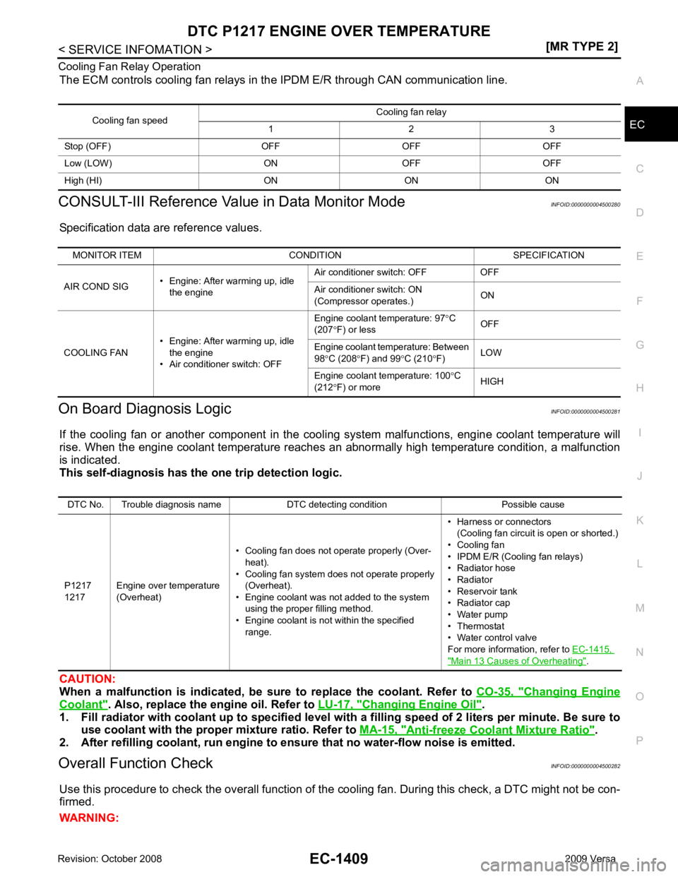
Cooling Fan Relay Operation
The ECM controls cooling fan relays in the IPDM E/R through CAN communication line.
CONSULT-III Reference Val ue in Data Monitor Mode INFOID:0000000004500280
Specification data are reference values.
On Board Diagnosis Logic INFOID:0000000004500281
If the cooling fan or another component in the cooli ng system malfunctions, engine coolant temperature will
rise. When the engine coolant temperature reaches an abnormally high temperature condition, a malfunction
is indicated.
This self-diagnosis has the on e trip detection logic.
CAUTION:
When a malfunction is in dicated, be sure to replace the coolant. Refer to CO-35, " Changing Engine
Coolant " . Also, replace the engine oil. Refer to
LU-17, " Changing Engine Oil " .
1. Fill radiator with coolant up to specified level with a filling speed of 2 liters per minute. Be sure to
use coolant with the proper mixture ratio. Refer to MA-15, " Anti-freeze Coolant Mixture Ratio " .
2. After refilling coolant, run engine to ensure that no water-flow noise is emitted.
Overall Function Check INFOID:0000000004500282
Use this procedure to check the overall function of the cooling fan. During this check, a DTC might not be con-
firmed.
WARNING: Cooling fan speed
Cooling fan relay
1 2 3
Stop (OFF) OFF OFF OFF
Low (LOW) ON OFF OFF
High (HI) ON ON ON MONITOR ITEM CONDITION SPECIFICATION
AIR COND SIG • Engine: After warming up, idle
the engine Air conditioner switch: OFF OFF
Air conditioner switch: ON
(Compressor operates.) ON
COOLING FAN • Engine: After warming up, idle
the engine
• Air conditioner switch: OFF Engine coolant temperature: 97
°C
(207 °F) or less OFF
Engine coolant temperature: Between
98 °C (208 °F) and 99 °C (210 °F) LOW
Engine coolant temperature: 100 °C
(212 °F) or more HIGHDTC No. Trouble diagnosis name DTC detecting condition Possible cause
P1217
1217 Engine over temperature
(Overheat) • Cooling fan does not operate properly (Over-
heat).
• Cooling fan system does not operate properly (Overheat).
• Engine coolant was not added to the system using the proper filling method.
• Engine coolant is not within the specified
range. • Harness or connectors
(Cooling fan circuit is open or shorted.)
• Cooling fan
• IPDM E/R (Cooling fan relays)
• Radiator hose
• Radiator
• Reservoir tank
• Radiator cap
• Water pump
• Thermostat
• Water control valve
For more information, refer to EC-1415, " Main 13 Causes of Overheating " .
Page 2769 of 4331
EC
NP
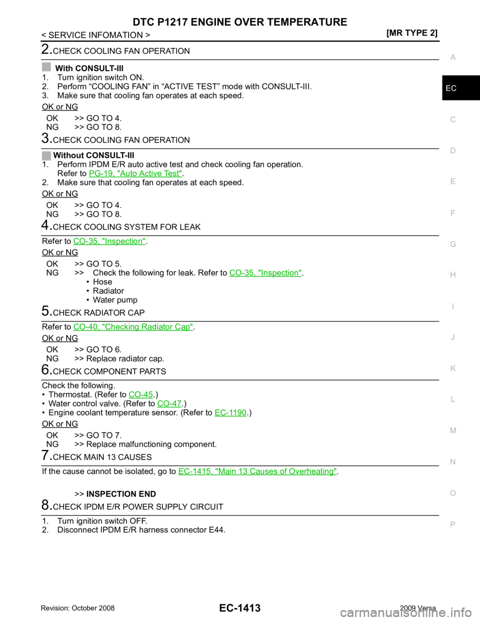
O OK >> GO TO 4.
NG >> GO TO 8. Auto Active Test " .
2. Make sure that cooling fan operates at each speed.
OK or NG OK >> GO TO 4.
NG >> GO TO 8. Inspection " .
OK or NG OK >> GO TO 5.
NG >> Check the following for leak. Refer to CO-35, " Inspection " .
• Hose
• Radiator
• Water pump Checking Radiator Cap " .
OK or NG OK >> GO TO 6.
NG >> Replace radiator cap. .)
• Water control valve. (Refer to CO-47 .)
• Engine coolant temperature sensor. (Refer to EC-1190 .)
OK or NG OK >> GO TO 7.
NG >> Replace malfunctioning component. Main 13 Causes of Overheating " .
>> INSPECTION END
Page 2771 of 4331
EC
NP
O
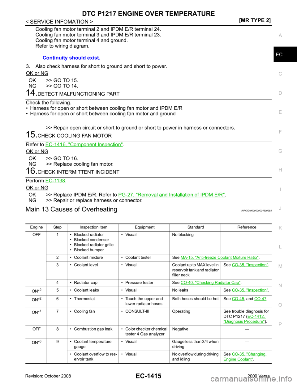
Cooling fan motor terminal 2 and IPDM E/R terminal 24.
Cooling fan motor terminal 3 and IPDM E/R terminal 23.
Cooling fan motor terminal 4 and ground.
Refer to wiring diagram.
3. Also check harness for short to ground and short to power.
OK or NG OK >> GO TO 15.
NG >> GO TO 14. Component Inspection " .
OK or NG OK >> GO TO 16.
NG >> Replace cooling fan motor. .
OK or NG OK >> Replace IPDM E/R. Refer to
PG-27, " Removal and Installation of IPDM E/R " .
NG >> Repair or replace harness or connector.
Main 13 Causes of Overheating INFOID:0000000004500285
Continuity should exist.
Engine Step Inspection item Equipment Standard Reference OFF 1 • Blocked radiator • Blocked condenser
• Blocked radiator grille
• Blocked bumper • Visual No blocking —
2 • Coolant mixture • Coolant tester See MA-15, " Anti-freeze Coolant Mixture Ratio " .
3 • Coolant level • Visual Coolant up to MAX level in reservoir tank and radiator
filler neck See
CO-35, " Inspection " .
4 • Radiator cap • Pressure tester See CO-40, " Checking Radiator Cap " .
ON* 2
5 • Coolant leaks • Visual No leaks See CO-35, " Inspection " .
ON* 2
6 • Thermostat • Touch the upper and
lower radiator hosesBoth hoses should be hot See
CO-45 , and
CO-47 ON*
1
7 • Cooling fan • CONSULT-III Operating See trouble diagnosis for
DTC P1217 (EC-1412, " Diagnosis Procedure " ).
OFF 8 • Combustion gas leak • Color checker chemical tester 4 Gas analyzerNegative —
ON* 3
9 • Coolant temperature
gauge • Visual Gauge less than 3/4 when
driving —
• Coolant overflow to res- ervoir tank • Visual No overflow during driving
and idling See
CO-35, " Changing
Engine Coolant " .