Back seat NISSAN TIIDA 2009 Service Repair Manual
[x] Cancel search | Manufacturer: NISSAN, Model Year: 2009, Model line: TIIDA, Model: NISSAN TIIDA 2009Pages: 4331, PDF Size: 58.04 MB
Page 442 of 4331
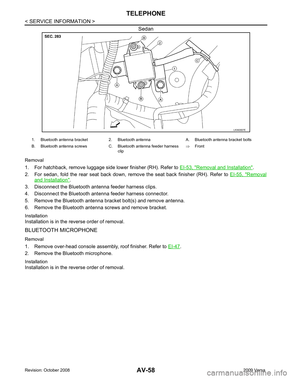
Removal and Installation " .
2. For sedan, fold the rear seat back down, re move the seat back finisher (RH). Refer to EI-55, " Removal
and Installation " .
3. Disconnect the Bluetooth antenna feeder harness clips.
4. Disconnect the Bluetooth ant enna feeder harness connector.
5. Remove the Bluetooth antenna bracket bolt(s) and remove antenna.
6. Remove the Bluetooth antenna screws and remove bracket.
Installation
Installation is in the reverse order of removal.
BLUETOOTH MICROPHONE
Removal
1. Remove over-head console assembly, roof finisher. Refer to EI-47 .
2. Remove the Bluetooth microphone.
Installation
Installation is in the reverse order of removal.
Page 449 of 4331

BCS
N
O P
CAN Communication System Description INFOID:0000000004306834
Refer to LAN-8, " System Description " .
Panic alarm
• Key switch
• Keyfob IPDM E/R
Vehicle security system • All door switches
• Keyfob
• Door lock/unlock switch
• Trunk key cylinder switch (Se-
dan)
• Front door key cylinder switch LH • IPDM/ER
• Security indicator lamp
Battery saver control • Ignition switch
• Combination switch IPDM E/R
Headlamp Combination switch IPDM E/R
Tail lamp Combination switch IPDM E/R
Front fog lamp (with front fog lamps) Combination switch IPDM E/R
Turn signal lamp Combination switch • Turn signal lamp
• Combination meter
Hazard lamp Hazard switch • Turn signal lamp
• Combination meter
Room lamp timer • Key switch
• Keyfob
• Main power window and door lock/unlock switch
• Front door switch LH
• All door switch Interior room lamp
Back door switch signal (Hatchback) Back door lock assembly Luggage room lamp
Back door lock signal (Hatchback) Back door lock assembly Back door opener
Trunk lamp switch signal (Sedan) Trunk lamp switch and trunk re-
lease solenoid Luggage room lamp
Trunk lid opener signal (Sedan) Trunk lamp switch and trunk re-
lease solenoid Trunk lid opener
Key warning chime • Key switch
• Front door switch LH Combination meter (warning buzzer)
Light warning chime • Combination switch
• Key switch
• Front door switch LH Combination meter (warning buzzer)
Seat belt warning chime • Seat belt buckle switch LH
• Ignition switch Combination meter (warning buzzer)
Front wiper and washer system • Combination switch
• Ignition switch IPDM E/R
Rear window defogger Rear window defogger switch IPDM E/R
Rear wiper and washer system
(Hatchback) • Combination switch
• Ignition switch Rear wiper motor
A/C switch signal Front air control ECM
Blower fan switch signal Front air control ECM
A/C indicator signal Front air control A/C indicator
Low tire pressure warning system Remote keyless entry receiver Combination meter System Input Output
Page 462 of 4331

BL
N
O P
CONTENTS
BODY, LOCK & SECURITY SYSTEM
SERVICE INFORMATION .. ..........................4
PRECAUTIONS .............................................. .....4
Precaution for Supplemental Restraint System
(SRS) "AIR BAG" and "SEAT BELT PRE-TEN-
SIONER" ............................................................. ......
4
Precaution Necessary fo r Steering Wheel Rota-
tion After Battery Disconnect ............................... ......
4
Precaution for Procedure without Cowl Top Cover ......5
Precaution for Work ............................................ ......5
PREPARATION .............................................. .....6
Special Service Tool ........................................... ......6
Commercial Service Tool .................................... ......6
SQUEAK AND RATTLE TROUBLE DIAG-
NOSES ........................ ........................................7
Work Flow ........................................................... ......7
Generic Squeak and Rattle Troubleshooting ...... ......9
Diagnostic Worksheet ......................................... ....11
HOOD ............................................................. ....13
Fitting Adjustment ............................................... ....13
Removal and Installation .........................................14
Removal and Installation of Hood Lock Control .. ....15
Hood Lock Control Inspec tion .................................17
RADIATOR CORE SUPPORT ....................... ....19
Removal and Installation .........................................19
FRONT FENDER ............................................ ....21
Removal and Installation .........................................21
POWER DOOR LOCK SYSTEM .................... ....22
Component Parts and Harness Connector Loca-
tion ...................................................................... ....
22
System Description ............................................. ....23
CAN Communication System Description ........... ....25
Schematic ........................................................... ....26
Wiring Diagram - D/LOCK - ................................. ....27
Schematic ........................................................... ....31
Wiring Diagram - D/LOCK - ................................. ....32 Terminal and Reference
Value for BCM ..................37
Work Flow ............................................................ ....41
CONSULT-III Function (B CM) .................................41
Trouble Diagnosis Symptom Chart ...................... ....43
BCM Power Supply and Ground Circuit Inspection ....43
Door Switch Check (Hatchback) .......................... ....44
Door Switch Check (Sedan) ................................ ....47
Key Switch (Insert) Check ................................... ....48
Door Lock and Unlock Switch Check .................. ....49
Front Door Lock Assembly LH (Actuator) Check .....52
Door Lock Actuator Check (Front RH and Rear
LH/RH) ................................................................. ....
53
Front Door Key Cylinder S witch LH Check ..............54
Passenger Select Unlock Relay Circuit Inspection
(With Intelligent Key) ........................................... ....
55
REMOTE KEYLESS ENTRY SYSTEM ............. 58
Component Parts and Harness Connector Loca-
tion ....................................................................... ....
58
System Description .............................................. ....58
CAN Communication System Description ........... ....60
Schematic ............................................................ ....61
Wiring Diagram - KEYLES - ................................ ....62
Terminal and Reference Value for BCM ..................65
How to Perform Trouble Diagnosis ...................... ....69
Preliminary Check ............................................... ....69
CONSULT-III Function (B CM) .................................69
Work Flow ............................................................ ....71
Trouble Diagnosis Symptom Chart ...................... ....71
Keyfob Battery and Function Check .................... ....72
ACC Switch Check .............................................. ....74
Door Switch Check (Hatchback) .......................... ....74
Door Switch Check (Sedan) ................................ ....76
Key Switch (Insert) Check ................................... ....78
Hazard Function Check ....................................... ....78
Horn Function Check ........................................... ....79
Interior Lamp and Ignition Keyhole Illumination
Function Check .................................................... ....
79
Remote Keyless Entry Rece iver Check ...................80
Keyfob Function (Lock) Check ............................ ....82
Page 934 of 4331
![NISSAN TIIDA 2009 Service Repair Manual CO-40< SERVICE INFORMATION >
[MR18DE]
RADIATOR
Checking Radiator Cap INFOID:0000000004305238
• Check valve seat of radiator cap.
- Check if valve seat is swollen to the extent that the e](/img/5/57398/w960_57398-933.png "NISSAN TIIDA 2009 Service Repair Manual CO-40< SERVICE INFORMATION >
[MR18DE]
RADIATOR
Checking Radiator Cap INFOID:0000000004305238
• Check valve seat of radiator cap.
- Check if valve seat is swollen to the extent that the e")
CO-40< SERVICE INFORMATION >
[MR18DE]
RADIATOR
Checking Radiator Cap INFOID:0000000004305238
• Check valve seat of radiator cap.
- Check if valve seat is swollen to the extent that the edge of the plunger cannot be seen when watching it vertically from the top.
- Check if valve seat has no soil and damage.
• Pull negative-pressure valve to open it, and make sure that it is completely closed when released.
- Make sure that there is no dirt or damage on the valve seat of radi-
ator cap negative-pressure valve.
- Make sure that the valve operates properly in the opening and closing conditions.
• Check radiator cap relief pressure using Tool.
- When connecting the radiator cap to the tester, apply water or coolant to the cap seal surface.
- Replace the radiator cap if ther e is an abnormality in the negative-
pressure valve, or if the open-valve pr essure is outside of the standard values.
• Replace radiator cap if there it does not comply to specifications to the above three checks.
CAUTION:
When installing radiator cap, thoroughly wipe out the radiator filler neck to remove any waxy residue
or foreign material.
Checking Radiator INFOID:0000000004305239
Check radiator for mud or clogging. If necessary, clean radiator as follows.
• Be careful not to bend or damage radiator fins.
• When radiator is cleaned without removal, remove all surrounding parts such as cooling fan, radiator shroud and horns. Then tape harness and connectors to prevent water from entering.
1. Apply water by hose to the back side of the radiator core vertically downward.
2. Apply water again to all radiator core surface once per minute.
3. Stop washing if any stains no longer flow out from radiator.
4. Blow air into the back side of radiator core vertically downward. • Use compressed air lower than 490 kPa (4.9 bar, 5 kg/cm 2
, 71 psi) and keep distance more than 30 cm
(11.8 in).
5. Blow air again into all the radiator core surfaces once per minute until no water sprays out. PBIC2816E
SMA967B
Tool number : EG17650301 (J-33984-A)
Standard: 78 – 98 kPa (0.78 - 0.98 bar, 0.8 – 1.0 kg/cm 2
, 11
– 14 psi)
Limit: 59 kPa (0.59 bar, 0.6 kg/cm 2
, 9 psi) WBIA0570E
Page 2892 of 4331

EI
N
O P
CONTENTS
EXTERIOR & INTERIOR
PRECAUTION ....... ........................................3
PRECAUTIONS .............................................. .....3
Precaution for Supplemental Restraint System
(SRS) "AIR BAG" and "SEAT BELT PRE-TEN-
SIONER" ............................................................. ......
3
Precaution Necessary fo r Steering Wheel Rota-
tion After Battery Disconnect ............................... ......
3
Precaution ........................................................... ......4
PREPARATION .... ........................................5
PREPARATION .............................................. .....5
Special Service Tool ........................................... ......5
Commercial Service Tool .................................... ......5
SYMPTOM DIAGNOSIS ..... ..........................6
SQUEAK AND RATTLE TROUBLE DIAGNO-
SIS .................................................................. .....6
Work Flow ........................................................... ......6
Generic Squeak and Rattle Troubleshooting ...... ......8
Diagnostic Worksheet ......................................... ....10
CLIP AND FASTENER ................................... ....12
Description .......................................................... ....12
ON-VEHICLE REPAIR .... .............................15
FRONT BUMPER ........................................... ....15
Removal and Installation .........................................15
REAR BUMPER ............................................. ....17
Component .......................................................... ....17
Removal and Installation - Hatchback .....................18
Removal and Installation - Sedan ....................... ....19
FRONT GRILLE ............................................. ....21
Removal and Installation .........................................21
COWL TOP ..................................................... ....22
Removal and Installation .........................................22 FENDER PROTECTOR ....................................
24
Component .......................................................... ....24
Removal and Installation ..................................... ....24
ROOF SIDE MOLDING ..................................... 25
Component .......................................................... ....25
Removal and Installation ..................................... ....25
DOOR OUTSIDE MOLDING ............................. 27
Component .......................................................... ....27
Removal and Installation ..................................... ....28
CENTER MUD GUARD ..................................... 30
Removal and Installation ..................................... ....30
TRUNK LID FINISHER ...................................... 31
Removal and Installation ..................................... ....31
REAR AIR SPOILER ......................................... 32
Removal and Installation ..................................... ....32
DOOR FINISHER .............................................. 34
Removal and Installation ..................................... ....34
BACK DOOR TRIM ........................................... 38
Removal and Installation ..................................... ....38
BODY SIDE TRIM ............................................. 39
Component .......................................................... ....39
Removal and Installation ..................................... ....40
REAR PARCEL SHELF FINISHER .................. 44
Removal and Installation ..................................... ....44
FLOOR TRIM .................................................... 45
Removal and Installation ..................................... ....45
HEADLINING .................................................... 47
Component .......................................................... ....47
Removal and Installation - Hatchback ................. ....49
Removal and Installation - Sedan ........................ ....51
LUGGAGE FLOOR TRIM ................................. 53
Page 2900 of 4331

EI
N
O P
3. The trunk lid torsion bars knocking together
4. A loose license plate or bracket
Most of these incidents can be repaired by adjusting, se curing or insulating the item(s) or component(s) caus-
ing the noise.
SUNROOF/HEADLINING Noises in the sunroof/headlining area can often be traced to one of the following:
1. Sunroof lid, rail, linkage or seals making a rattle or light knocking noise
2. Sun visor shaft shaking in the holder
3. Front or rear windshield touching headliner and squeaking
Again, pressing on the components to stop the noise while duplicating the conditions can isolate most of these
incidents. Repairs usually consist of insulating with felt cloth tape.
OVERHEAD CONSOLE (FRONT AND REAR) Overhead console noises are often caused by the cons ole panel clips not being engaged correctly. Most of
these incidents are repaired by pushing up on the c onsole at the clip locations until the clips engage.
In addition look for:
1. Loose harness or harness connectors.
2. Front console map/reading lamp lens loose.
3. Loose screws at console attachment points.
SEATS When isolating seat noise it's important to note the pos ition the seat is in and the load placed on the seat when
the noise is present. These conditions should be duplic ated when verifying and isolating the cause of the
noise.
Cause of seat noise include:
1. Headrest rods and holder
2. A squeak between the seat pad cushion and frame
3. The rear seatback lock and bracket
These noises can be isolated by moving or pressing on the suspected components while duplicating the con-
ditions under which the noise occurs. Most of thes e incidents can be repaired by repositioning the component
or applying urethane tape to the contact area.
UNDERHOOD Some interior noise may be caused by components under the hood or on the engine wall. The noise is then
transmitted into the passenger compartment.
Causes of transmitted underhood noise include:
1. Any component installed on the engine wall
2. Components that pass through the engine wall
3. Engine wall mounts and connectors
4. Loose radiator pins
5. Hood bumpers out of adjustment
6. Hood striker out of adjustment
These noises can be difficult to isolate since they cannot be reached from the interior of the vehicle. The best
method is to secure, move or insulate one component at a time and test drive the vehicle. Also, engine RPM
or load can be changed to isolate the noise. Repairs c an usually be made by moving, adjusting, securing, or
insulating the component causing the noise.
Page 2924 of 4331
EI
N
O P
2. Remove the rear spoiler nuts.
3. Remove inside trunk lid finisher. Refer to EI-55, " Removal and Installation " .
4. Disconnect high mounted stop lamp connector.
5. Release adhesive backed foam tape and clips, then carefully lift the rear air spoiler from trunk lid. CAUTION:
Use care not to damage painted surfaces during removal, or releasing of adhesive backed foam
tapes if equipped.
6. Release the high mounted stop lamp harness grommet from trunk lid, then remove rear air spoiler.
Installation - Sedan Installation is in the reverse order of removal.
NOTE:
• Before installing rear air spoiler, clean the surface where it will be mounted with isopropyl alcohol or equiva-
lent to degrease the surface.
• Before installing, be sure there are no gaps or wa ves in the foam tape (if equipped) where the surfaces
meet.
• During installation, be sure grommet of high mounted stop lamp harness is fully seated into trunk lid opening
prior to final rear air spoiler placement.
Removal - Hatchback 1. Disconnect the negative battery terminal.
2. Remove back door finisher upper. Refer to EI-38 .
3. Disconnect high mounted stop lamp connector.
4. Remove the nuts and carefully lift the rear air spoiler from the back door. CAUTION:
Use care not to damage painted surfaces during removal, or releasing of adhesive backed foam
tapes if equipped.
5. Release the high mounted stop lamp harness grommet from back door, then remove rear air spoiler.
Installation - Hatchback Installation is in the reverse order of removal.
NOTE:
• Before installing rear air spoiler, clean the surface where it will be mounted with isopropyl alcohol or equiva-
lent to degrease the surface.
• Before installing, be sure there are no gaps or wa ves in the foam tape (if equipped) where the surfaces
meet.
• During installation, be sure grommet of high mount ed stop lamp harness is fully seated into back door open-
ing prior to final rear air spoiler placement.
Page 2934 of 4331
EI
N
O P
WARNING:
Do not reuse center pillar upper garnish if removed.
1. Remove center pillar lower garnish.
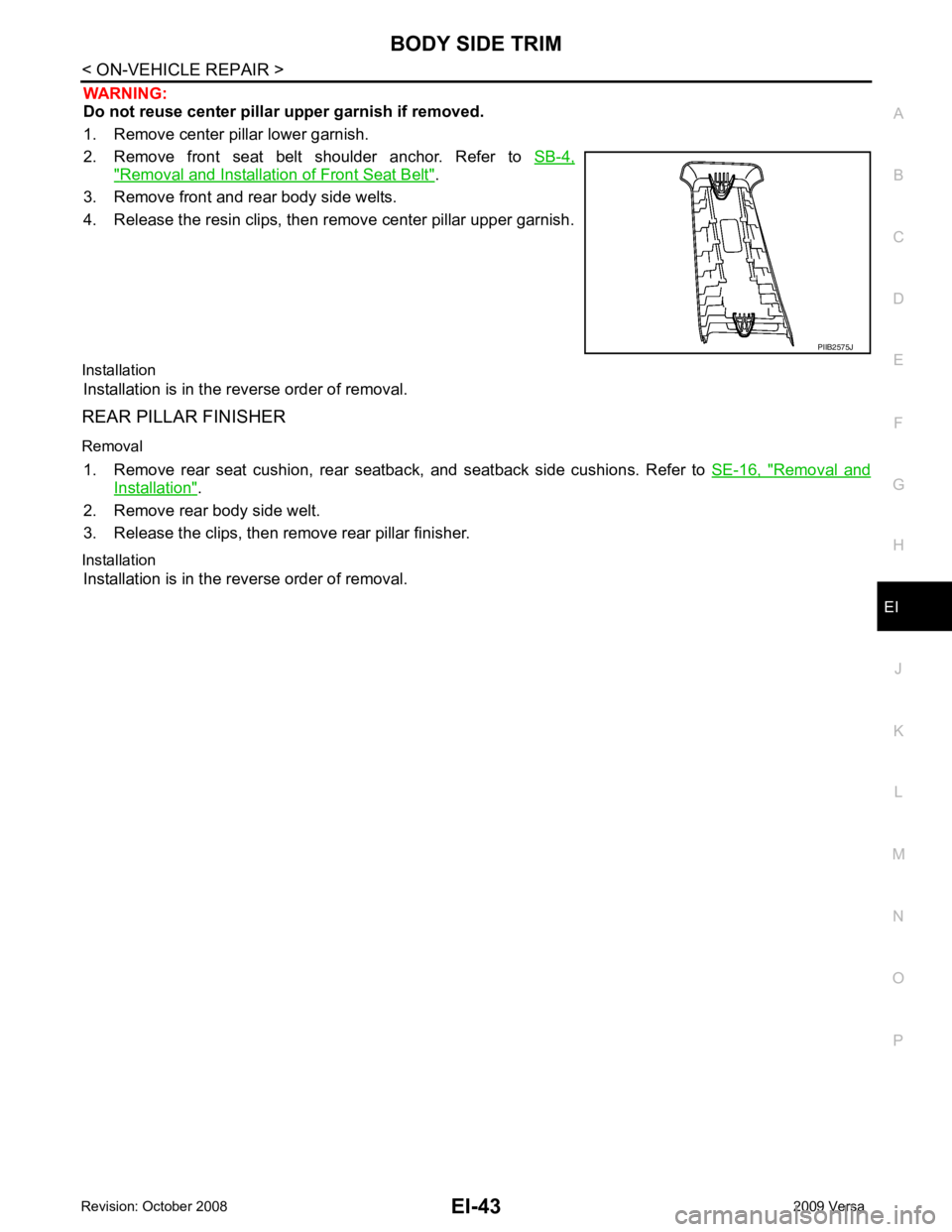
2. Remove front seat belt shoulder anchor. Refer to SB-4," Removal and Installation of Front Seat Belt " .
3. Remove front and rear body side welts.
4. Release the resin clips, then remove center pillar upper garnish.
Installation Installation is in the reverse order of removal.
REAR PILLAR FINISHER
Removal 1. Remove rear seat cushion, rear seat back, and seatback side cushions. Refer to SE-16, " Removal and
Installation " .
2. Remove rear body side welt.
3. Release the clips, then remove rear pillar finisher.
Installation Installation is in the reverse order of removal.
Page 2940 of 4331
EI
N
O P
Removal and Installation - Hatchback
INFOID:0000000004307236
REMOVAL 1. Disconnect the negative and positive battery term inals, then wait at least three minutes.
2. Remove front seat assembly RH/LH. Refer to SE-12, " Removal and Installation " .
3. Remove rear seat cushion and rear seatback. Refer to SE-16, " Removal and Installation " .
4. Remove front seat belt shoulder anchor RH/LH. Refer to SB-4, " Removal and Installation of Front Seat
Belt " .
5. Remove center console body assembly. Refer to IP-11 .
6. Remove front pillar garnish RH/LH. Refer to EI-40, " Removal and Installation " .
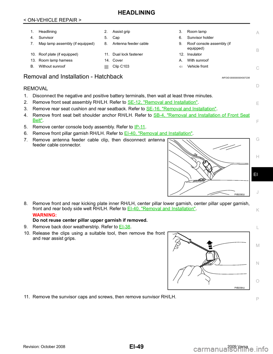
7. Remove antenna feeder cable clip, then disconnect antenna feeder cable connector.
8. Remove front and rear kicking plate inner RH/LH, cent er pillar lower garnish, center pillar upper garnish,
front and rear body side welt RH/LH. Refer to EI-40, " Removal and Installation " .
WARNING:
Do not reuse center pillar upper garnish if removed.
9. Remove back door weatherstrip. Refer to EI-38 .
10. Release the clips using a suitable tool, then remove the front and rear assist grips.
11. Remove the sunvisor caps and screws, then remove sunvisor RH/LH. 1. Headlining 2. Assist grip 3. Room lamp
4. Sunvisor 5. Cap 6. Sunvisor holder
7. Map lamp assembly (if equipped) 8. Antenna feeder cable 9. Roof console assembly (if equipped)
10. Roof plate (if equipped) 11. Dual lock fastener 12. Insulator
13. Room lamp harness 14. Cover A. With sunroof
B. Without sunroof Clip C103 ⇐Vehicle front PIIB2584J
Page 2942 of 4331
HEADLINING
EI-51
< ON-VEHICLE REPAIR >
C
D E
F
G H
J
K L
M A
B EI
N
O P
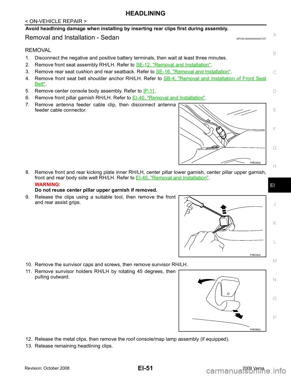
Avoid headlining damage when
installing by inserting rear clips first during assembly.
Removal and Installation - Sedan INFOID:0000000004307237
REMOVAL 1. Disconnect the negative and positive battery term inals, then wait at least three minutes.
2. Remove front seat assembly RH/LH. Refer to SE-12, " Removal and Installation " .
3. Remove rear seat cushion and rear seatback. Refer to SE-16, " Removal and Installation " .
4. Remove front seat belt shoulder anchor RH/LH. Refer to SB-4, " Removal and Installation of Front Seat
Belt " .
5. Remove center console body assembly. Refer to IP-11 .
6. Remove front pillar garnish RH/LH. Refer to EI-40, " Removal and Installation " .
7. Remove antenna feeder cable clip, then disconnect antenna feeder cable connector.
8. Remove front and rear kicking plate inner RH/LH, cent er pillar lower garnish, center pillar upper garnish,
front and rear body side welt RH/LH. Refer to EI-40, " Removal and Installation " .
WARNING:
Do not reuse center pillar upper garnish if removed.
9. Release the clips using a suitable tool, then remove the front and rear assist grips.
10. Remove the sunvisor caps and screws, then remove sunvisor RH/LH.
11. Remove sunvisor holders RH/LH by rotating 45 degrees, then pulling outward.
12. Release the metal clips, then remove the roof console/map lamp assembly (if equipped).
13. Release remaining headlining clips. PIIB2583J
PIIB2584J
PIIB3982J