Cvt NISSAN TIIDA 2009 Service Repair Manual
[x] Cancel search | Manufacturer: NISSAN, Model Year: 2009, Model line: TIIDA, Model: NISSAN TIIDA 2009Pages: 4331, PDF Size: 58.04 MB
Page 554 of 4331

BL
N
O P
Even if Intelligent Key battery runs down, Intelligent
key unit can start engine with mechanical key built Intelli-
gent Key. For details, refer to BL-248 .
All of the originally supplied Intelligent Key IDs (exc ept for key) have been registered in Intelligent Key system.
If requested by the vehicle owner, a maximum of four Intelligent Key IDs can be registered into the Intelligent
Key system components.
List of Operation Related Parts Parts marked with × are the parts related to operation.
WARNING CHIME/BUZZER/LAMPS FUNCTION
Operation Description The following warning chime (combination meter), Intelligent Key warning buzzer (front door LH), Intelligent
Key warning buzzer (trunk) *
, warning lamps "KEY" and “P-SHIFT” (with CVT or A/T) or "LOCK" (with M/T) are
given to the user as warning informati on while using the intelligent key system.
• Ignition switch warning chime
• Ignition key warning chime
• OFF position warning chime
• Take away warning chime
• Door lock operation warning chime
• Intelligent key low battery warning
• P position warning (with CVT or A/T)
• LOCK position warning (with M/T) NOTE:
For key-in-ignition warning chime related concerns only, refer to DI-42 .
* : Sedan
Operation Condition Engine start functionsIntelligent Key
Key switch
Ignition knob switch
Inside key antenna
Intelligent Key unit
CAN communication system
BCM
Combination meter
IPDM E/R
NATS antenna amp.
Steering lock solenoid
Engine start function by the Intelligent Key × × × × × × × × × ×
Engine start function by the mechanical key × × × × × × ×
Page 571 of 4331
BL-110< SERVICE INFORMATION >
INTELLIGENT KEY SYSTEM
*1: With continuously variable transmissi on (CVT) or automatic transmission (A/T).
*2: With manual transmission (M/T).
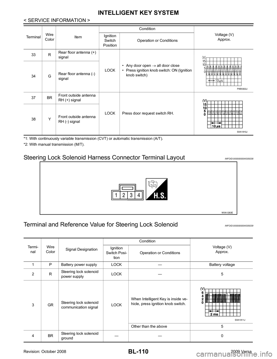
Steering Lock Solenoid Harn ess Connector Terminal Layout INFOID:0000000004305038
Terminal and Reference Valu e for Steering Lock Solenoid INFOID:0000000004305039
33 R
Rear floor antenna (+)
signal
LOCK• Any door open
→ all door close
• Press ignition knob switch: ON (Ignition knob switch)
34 G Rear floor antenna (-)
signal
37 BR Front outside antenna
RH (+) signal
LOCK Press door request switch RH.
38 Y Front outside antenna
RH (-) signal
Terminal
Wire
Color Item Condition
Voltage (V)Approx.
Ignition
Switch
Position Operation or Conditions PIIB5502J
SIIA1910J
WIIA1283E
Termi-
nal Wire
Color Signal Designation Condition
Voltage (V)Approx.
Ignition
Switch Posi- tion Operation or Conditions
1 P Battery power supply LOCK — Battery voltage
2 R Steering lock solenoid
power supply LOCK — 5
3 GR Steering lock solenoid
communication signal LOCKWhen Intelligent Key is inside ve-
hicle, press ignition knob switch.
Other than the above 5
4 BR Steering lock solenoid
ground — — 0 SIIA1911J
Page 582 of 4331
BL
N
O P
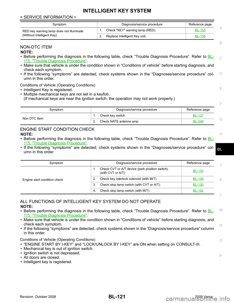
NON-DTC ITEM
NOTE:
• Before performing the diagnosis in the following table, check “Trouble Diagnosis Procedure”. Refer to BL-115, " Trouble Diagnosis Procedure " .
• Make sure that vehicle is under the condition shown in “Conditions of vehicle” before starting diagnosis, and
check each symptom.
• If the following “symptoms” are detected, check syst ems shown in the “Diagnoses/service procedure” col-
umn in this order.
Conditions of Vehicle (Operating Conditions) • Intelligent Key is registered.
• Multiple mechanical keys are not set in a keyfob. (If mechanical keys are near the ignition switch, the operation may not work properly.)
ENGINE START CONDITION CHECK NOTE:
• Before performing the diagnosis in the following table, check “Trouble Diagnosis Procedure”. Refer to BL-115, " Trouble Diagnosis Procedure " .
• If the following “symptoms” are detected, check syst ems shown in the ”Diagnoses/service procedure” col-
umn in this order.
ALL FUNCTIONS OF INTELLIGENT KEY SYSTEM DO NOT OPERATE
NOTE:
• Before performing the diagnosis in the following table, check “Trouble Diagnosis Procedure”. Refer to BL-115, " Trouble Diagnosis Procedure " .
• Make sure that vehicle is under the condition shown in “Conditions of vehicle” before starting diagnosis, and
check each symptom.
• If the following “symptoms” are detected, check syst ems shown in the “Diagnosis/service procedure” column
in this order.
Conditions of Vehicle (Operating Conditions) • “ENGINE START BY I-KEY” and “LOCK/UNLOCK BY I-KEY” are ON when setting on CONSULT-III.
• Mechanical key is out of ignition switch.
• Ignition switch is not depressed.
• All doors are closed.
• Intelligent key is registered. RED key warning lamp does not illuminate
[Without Intelligent Key]. 1. Check "KEY" warning lamp (RED).
BL-155 2. Replace Intelligent Key unit.
BL-158Symptom Diagnosis/service procedure Reference page
Symptom Diagnosis/service procedure Reference page
Non DTC Item 1. Check key switch.
BL-1272. Check NATS antenna amp.
BL-248Symptom Diagnosis/service procedure Reference page
Engine start condition check 1. Check CVT or A/T device (park position switch).
(with CVT or A/T) BL-153 2. Check key interlock solenoid (with M/T).
BL-1493. Check stop lamp switch (with CVT or A/T).
BL-1504. Check stop lamp switch (with M/T).
BL-152
Page 587 of 4331
![NISSAN TIIDA 2009 Service Repair Manual NO DTC IS DETECT
ED>> Inspection End.
CAN COMM [U1000]>> After printing “SELF-DIAGNOSI S RESULTS”, go to “CAN SYSTEM”. Refer to LAN-17, " Trouble Diagnosis Flow Chart " .
CAN COMM2 [U1010] >>](/img/5/57398/w960_57398-586.png "NISSAN TIIDA 2009 Service Repair Manual NO DTC IS DETECT
ED>> Inspection End.
CAN COMM [U1000]>> After printing “SELF-DIAGNOSI S RESULTS”, go to “CAN SYSTEM”. Refer to LAN-17, \" Trouble Diagnosis Flow Chart \" .
CAN COMM2 [U1010] >>")
NO DTC IS DETECT
ED>> Inspection End.
CAN COMM [U1000]>> After printing “SELF-DIAGNOSI S RESULTS”, go to “CAN SYSTEM”. Refer to LAN-17, " Trouble Diagnosis Flow Chart " .
CAN COMM2 [U1010] >> Replace Intelligent Key unit. Refer to BL-158, " Removal and Installation of Intelli-
gent Key Unit " .
Power Supply and Ground Circuit Inspection INFOID:00000000043050462. Check Intelligent Key battery.
BL-158 3. Check KEY warning lamp (green).
BL-155 4. Replace Intelligent Key unit.
BL-158P position warning lamp does not illuminate properly.
(With CVT or A/T) 1. Check CVT or A/T device (park position switch).
BL-153 2. Check “P-SHIFT” warning lamp (red).
BL-154 3. Replace Intelligent Key unit.
BL-158LOCK warning lamp does not illuminate properly.
(With M/T) 1. Check key interlock solenoid.
BL-149 2. Check "LOCK" warning lamp.
BL-155 3. Replace Intelligent Key unit.
BL-158Take away warning lamp does not illuminate properly.
(Take away warning chime is operated). 1. Check KEY warning lamp (red).
BL-158 2. Replace Intelligent Key unit.
BL-158Ignition switch warning lamp does not illuminate properly.
(Ignition switch warning chime is operated). 1. Check KEY warning lamp (red).
BL-155 2. Replace Intelligent Key unit.
BL-158CONSULT-III display item DTC code
NO DTC IS DETECTED — CAN COMM U1000
CAN COMM2 U1010
Page 611 of 4331
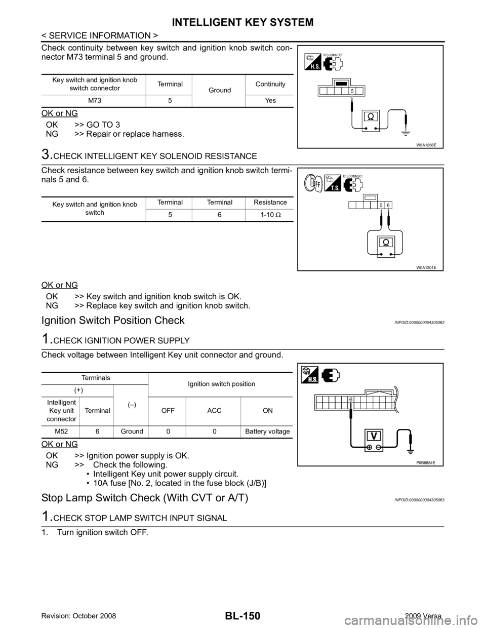
OK >> GO TO 3
NG >> Repair or replace harness. OK >> Key switch and ignition knob switch is OK.
NG >> Replace key switch and ignition knob switch.
Ignition Switch Position Check INFOID:0000000004305062OK >> Ignition power supply is OK.
NG >> Check the following.
• Intelligent Key unit power supply circuit.
• 10A fuse [No. 2, located in the fuse block (J/B)]
Stop Lamp Switch Check (With CVT or A/T) INFOID:0000000004305063
Page 614 of 4331
BL
N
O P
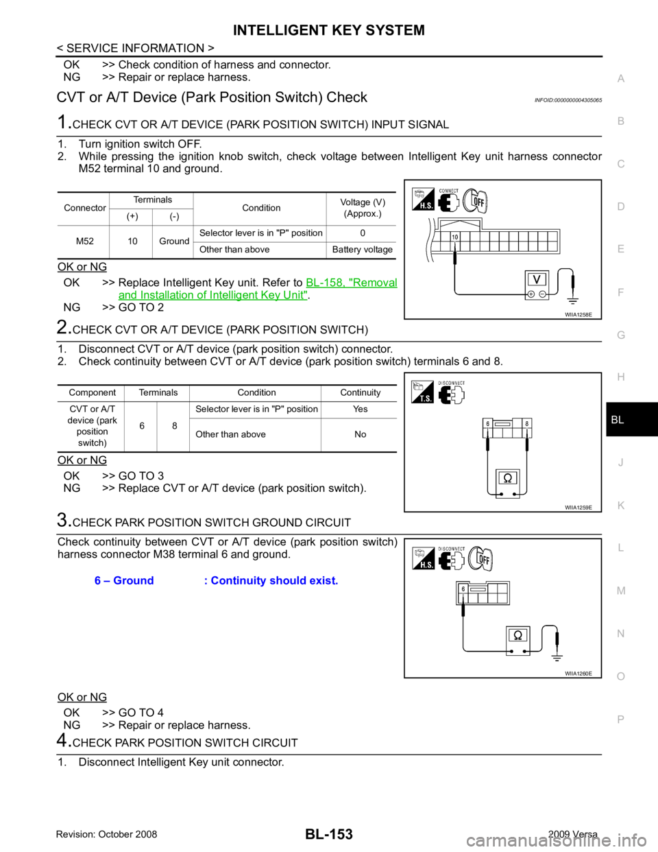
OK >> Check condition of harness and connector.
NG >> Repair or replace harness.
CVT or A/T Device (Park Position Switch) Check INFOID:0000000004305065OK >> Replace Intelligent Key unit. Refer to
BL-158, " Removal
and Installation of Intelligent Key Unit " .
NG >> GO TO 2 OK >> GO TO 3
NG >> Replace CVT or A/T device (park position switch). OK >> GO TO 4
NG >> Repair or replace harness.
Page 615 of 4331
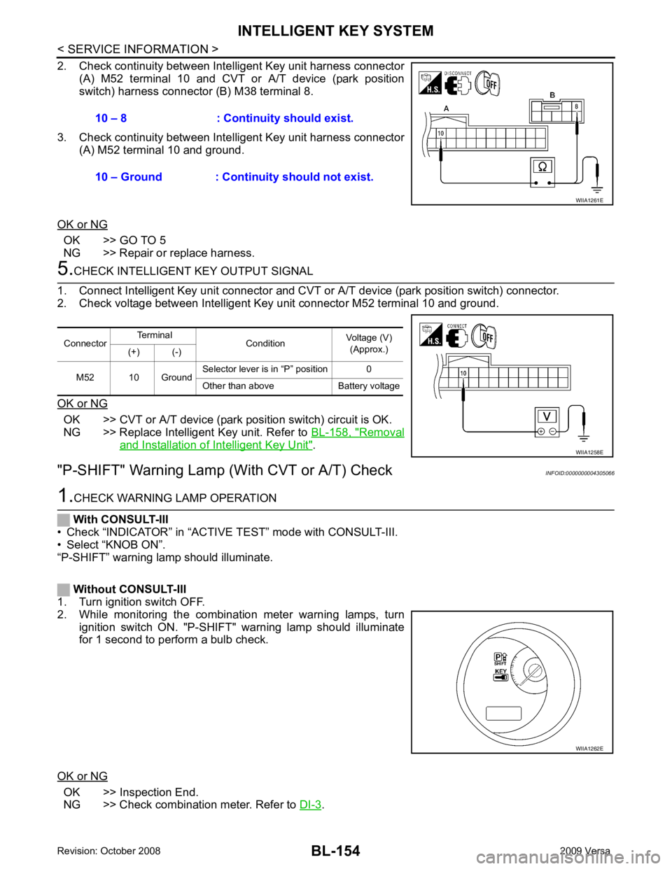
OK >> GO TO 5
NG >> Repair or replace harness. OK >> CVT or A/T device (park position switch) circuit is OK.
NG >> Replace Intelligent Key unit. Refer to BL-158, " Removal
and Installation of Intelligent Key Unit " .
"P-SHIFT" Warning Lamp (With CVT or A/T) Check INFOID:0000000004305066OK >> Inspection End.
NG >> Check combination meter. Refer to DI-3 .
10 – 8 : Continuity should exist.
10 – Ground : Continuity should not exist. WIIA1262E
Page 640 of 4331

BL
N
O P
1: With Intelligent Key
2: Without Intelligent Key
3: Hatchback without Intelligent Key
4: Sedan without Intelligent Key
5: Hatchback
6: Sedan
7: With power door locks
8: With power windows
Terminal and Reference Valu e for Intelligent Key Unit INFOID:0000000004678879
65
7
SBAll door lock actuators
(lock) Output OFFOFF (neutral) 0V
ON (lock) Battery voltage
66 7
GFront door lock actua-
tor RH, rear door lock
actuators LH/RH (un-
lock) Output OFFOFF (neutral) 0V
ON (unlock) Battery voltage
67 B Ground Input ON — 0V
68 8
LPower window power
supply (RAP) Output —Ignition switch ON Battery voltage
Within 45 seconds after igni-
tion switch OFF Battery voltage
More than 45 seconds after ig-
nition switch OFF 0V
When front door LH or RH is
open or power window timer
operates 0V
69 8
P Battery power supply
OutputOFF
— Battery voltage
70 Y Battery power supply Input OFF — Battery voltage
Terminal
Wire
color Signal name Signal
input/
output Measuring condition
Reference value or waveform
(Approx.)
Ignition
switch Operation or condition Terminal
Wire
Color Item Condition
Voltage (V)Approx.
Ignition
Switch
Position Operation or Conditions
1 R Steering lock solenoid
power supply LOCK — 5
2 L CAN-H — — —
3 P CAN-L — — —
4 O Intelligent Key warning
buzzer LOCKOperate door request
switch. Buzzer OFF Battery voltage
Sound buzzer 0
5 G Front door request
switch LH —Press door request switch (driver side). 0
Other than above 5
6 Y Ignition switch (ON) ON — Battery voltage
7 LG Key switch LOCK Insert mechanical key into ignition switch. Battery voltage
Remove mechanical key from ignition
switch. 0
10 *1
WCVT or A/T device
(park position switch) ONShift lever in park position. 0
Other than above Battery voltage
11 SB Power source (Fus e) — — Battery voltage
12 B Ground — — 0
Page 642 of 4331
BACK DOOR LOCK
BL-181
< SERVICE INFORMATION >
C
D E
F
G H
J
K L
M A
B BL
N
O P
*1: With continuously variable transmission (CVT) or automatic transmission (A/T).
*2: With manual transmission (M/T).
CONSULT-III Function (BCM) INFOID:0000000004305088
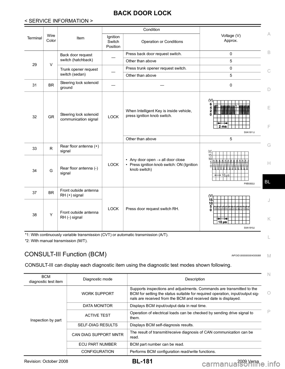
CONSULT-III can display each diagnostic item using the diagnostic test modes shown following. 29 V
Back door request
switch (hatchback) —Press back door request switch. 0
Other than above 5
Trunk opener request
switch (sedan) —Press trunk opener request switch. 0
Other than above 5
31 BR Steering lock solenoid
ground — — 0
32 GR Steering lock solenoid
communication signal LOCKWhen Intelligent Key is inside vehicle,
press ignition knob switch.
Other than above 5
33 R Rear floor antenna (+)
signal
LOCK• Any door open
→ all door close
• Press ignition knob switch: ON (Ignition
knob switch)
34 G Rear floor antenna (-)
signal
37 BR Front outside antenna
RH (+) signal
LOCK Press door request switch RH.
38 Y Front outside antenna
RH (-) signal
Terminal
Wire
Color Item Condition
Voltage (V)Approx.
Ignition
Switch
Position Operation or Conditions SIIA1911J
PIIB5502J
SIIA1910J
BCM
diagnostic test item Diagnostic mode Description
Inspection by part WORK SUPPORT
Supports inspections and adjustments. Commands are transmitted to the
BCM for setting the status suitable for required operation, input/output sig-
nals are received from the BCM and received date is displayed.
DATA MONITOR Displays BCM input/output data in real time.
ACTIVE TEST Operation of electrical loads can be checked by sending drive signal to
them.
SELF-DIAG RESULTS Displays BC M self-diagnosis results.
CAN DIAG SUPPORT MNTR The result of transmit/receive diagnosis of CAN communication can be
read.
ECU PART NUMBER BCM part number can be read.
CONFIGURATION Performs BCM configuration read/write functions.
Page 664 of 4331

BL
N
O P
1: With Intelligent Key
2: Without Intelligent Key
3: Hatchback without Intelligent Key
4: Sedan without Intelligent Key
5: Hatchback
6: Sedan
7: With power door locks
8: With power windows
Terminal and Reference Valu e for Intelligent Key Unit INFOID:0000000004678894
65
7
SBAll door lock actuators
(lock) Output OFFOFF (neutral) 0V
ON (lock) Battery voltage
66 7
GFront door lock actua-
tor RH, rear door lock
actuators LH/RH (un-
lock) Output OFFOFF (neutral) 0V
ON (unlock) Battery voltage
67 B Ground Input ON — 0V
68 8
LPower window power
supply (RAP) Output —Ignition switch ON Battery voltage
Within 45 seconds after igni-
tion switch OFF Battery voltage
More than 45 seconds after ig-
nition switch OFF 0V
When front door LH or RH is
open or power window timer
operates 0V
69 8
P Battery power supply
OutputOFF
— Battery voltage
70 Y Battery power supply Input OFF — Battery voltage
Terminal
Wire
color Signal name Signal
input/
output Measuring condition
Reference value or waveform
(Approx.)
Ignition
switch Operation or condition Terminal
Wire
Color Item Condition
Voltage (V)Approx.
Ignition
Switch
Position Operation or Conditions
1 R Steering lock solenoid
power supply LOCK — 5
2 L CAN-H — — —
3 P CAN-L — — —
4 O Intelligent Key warning
buzzer LOCKOperate door request
switch. Buzzer OFF Battery voltage
Sound buzzer 0
5 G Front door request
switch LH —Press door request switch (driver side). 0
Other than above 5
6 Y Ignition switch (ON) ON — Battery voltage
7 LG Key switch LOCK Insert mechanical key into ignition switch. Battery voltage
Remove mechanical key from ignition
switch. 0
10 *1
WCVT or A/T device
(park position switch) ONShift lever in park position. 0
Other than above Battery voltage
11 SB Power source (Fus e) — — Battery voltage
12 B Ground — — 0