Ecm NISSAN TIIDA 2009 Service Repair Manual
[x] Cancel search | Manufacturer: NISSAN, Model Year: 2009, Model line: TIIDA, Model: NISSAN TIIDA 2009Pages: 4331, PDF Size: 58.04 MB
Page 14 of 4331
AT
N
O P
• The valve body contains precision parts and requires extreme care when parts are removed and serviced.
Place disassembled valve body parts in order for easier and proper assembly. Care will also prevent springs
and small parts from becoming scattered or lost.
• Properly installed valves, sleeves, plugs, etc. will slide along bores in valve body under their own weight.
• Before assembly, apply a coat of recommended ATF to all parts. Apply petroleum jelly to protect O-rings and
seals, or hold bearings and washers in pl ace during assembly. Do not use grease.
• Extreme care should be taken to avoid damage to O-rings, seals and gaskets when assembling.
• Clean or replace ATF cooler if excessive foreign material is found in oil pan or clogging strainer. Refer to AT-18, " A/T Fluid Cooler Cleaning " .
• After overhaul, refill the A/T with new ATF.
• When the A/T drain plug is removed, only some of the fluid is drained. Old A/T fluid will remain in torque con- verter and ATF cooling system.
Always follow the procedures under “Changing A/T Fluid” in the AT section when changing A/T fluid. Refer to
AT-17, " Changing A/T Fluid " ,
AT-17, " Checking A/T Fluid " .
Service Notice or Precaution INFOID:0000000004305292
ATF COOLER SERVICE If A/T fluid contains frictional material (clutches, bands, etc.), or if an A/T is repaired, overhauled, or replaced,
inspect and clean the A/T oil cooler mounted in the radiator or replace the radiator. Flush cooler lines using
cleaning solvent and compressed air after repair. Check Serv ice Bulletins for latest A/T oil cooler cleaning pro-
cedure. For radiator replacement, refer to CO-16, " Removal and Installation " (HR16DE engine models),
CO-38, " Removal and Installation " (MR18DE engine models).
TORQUE CONVERTER SERVICE The torque converter should be replaced under any of the following conditions:
• External leaks in the hub weld area.
• Converter hub is scored or damaged.
• Converter pilot is broken, damaged or fits poorly into crankshaft.
• Steel particles are found after flushing the cooler and cooler lines.
• Pump is damaged or steel particles are found in the converter.
• Vehicle has TCC shudder and/or no TCC apply. Replace only after all hydraulic and electrical diagnoses
have been made. (Converter clutch material may be glazed.)
• Converter is contaminated with engi ne coolant containing antifreeze.
• Internal malfunction of stator roller clutch.
• Heavy clutch debris due to overheating (blue converter).
• Steel particles or clutch lining material found in flui d filter or on magnet when no internal parts in unit are
worn or damaged — indicates that lining material came from converter.
The torque converter should not be replaced if:
• The fluid has an odor, is discolored, and there is no evidence of metal or clutch facing particles.
• The threads in one or more of the converter bolt holes are damaged.
• A/T malfunction did not display evidence of damaged or worn internal parts, steel particles or clutch plate lin-
ing material in unit and inside the fluid filter.
• Vehicle has been exposed to high mileage (only). The e xception may be where the torque converter clutch
dampener plate lining has seen excess wear by vehicles operated in heavy and/or constant traffic, such as
taxi, delivery or police use.
OBD-II SELF-DIAGNOSIS • A/T self-diagnosis is performed by the TCM in combination with the ECM. The results can be read through the blinking pattern of the OD OFF indicator lamp or the malfunction indicator lamp (MIL). Refer to the table
on AT-83, " Diagnosis Procedure without CONSULT-III " for the indicator used to display each self-diagnostic
result.
• The self-diagnostic results indicated by the MIL ar e automatically stored in both the ECM and TCM memo-
ries.
Always perform the procedure “HOW TO ERASE DTC” on AT-39, " OBD-II Diagnostic Trouble Code
(DTC) " to complete the repair and avo
id unnecessary blinking of the MIL.
• The following self-diagnostic items can be detected us ing ECM self-diagnostic results mode* only when the
OD OFF indicator lamp does not indicate any malfunctions.
- PNP switch
- A/T 1st, 2nd, 3rd, or 4th gear function
*: For details of OBD-II, refer to AT-39 .
Page 38 of 4331

AT
N
O P
The line pressure is temporarily reduced corresponding to a change
in engine torque when shifting gears (that is, when the shift solenoid
valve is switched for clutch operation) to reduce shifting shock.
AT LOW FLUID TEMPERATURE • A/T fluid viscosity and frictional characteristics of t he clutch facing change with A/T fluid temperature. Clutch
engaging or band-contacting pressure is compensated for, according to A/T fluid temperature, to stabilize
shifting quality.
• The line pressure is reduced below 60 °C (140 °F) to prevent shift-
ing shock due to high viscosity of A/T fluid when temperature is
low.
• Line pressure is increased to a maximum irrespective of the throt- tle opening when A/T fluid temperature drops to −10 °C (14 °F). This
pressure rise is adopted to prevent a delay in clutch and brake
operation due to extreme drop of A/T fluid viscosity at low temper-
ature.
Shift Control INFOID:0000000004305304
The shift is regulated entirely by electronic cont rol to accommodate vehicle speed and varying engine opera-
tions. This is accomplished by electrical signals trans mitted by the revolution sensor and the ECM (accelerator
pedal position sensor). This results in improved acceleration performance and fuel economy.
CONTROL OF SHIFT SOLENOID VALVES A AND B The TCM activates shift solenoid valves A and B according to sig-
nals from the accelerator pedal position sensor and revolution sen-
sor to select the optimum gear pos ition on the basis of the shift
schedule memorized in the TCM.
The shift solenoid valve performs simple ON-OFF operation. When
set to “ON”, the drain circuit closes and pilot pressure is applied to
the shift valve.
RELATION BETWEEN SHIFT SOLENOID VALVES A AND B AND GEAR POSITIONS SAT008J
Page 44 of 4331
AT
N
O P
ON BOARD DIAGNOSTIC (OBD) SYSTEM
Introduction INFOID:0000000004305309
A/T system has two self-diagnostic systems.
The first is emission-related on boar d diagnostic system (OBD-II) performed by the TCM in combination with
the ECM. The malfunction is indicated by the MIL (malf unction indicator lamp) and is stored as a DTC in the
ECM memory but not the TCM memory.
The second is the TCM original self-diagnosis indicated by the OD OFF indicator lamp. The malfunction is
stored in the TCM memory. The detected items are ov erlapped with OBD-II self-diagnostic items. For detail,
refer to AT-79, " CONSULT-III Function (TRANSMISSION) " .
OBD-II Function for A/T System INFOID:0000000004305310
The ECM provides emission-related on board diagnostic (O BD-II) functions for the A/T system. One function
is to receive a signal from the TCM used with OBD-rela ted parts of the A/T system. The signal is sent to the
ECM when a malfunction occurs in the corresponding OBD-re lated part. The other function is to indicate a
diagnostic result by means of the MIL (malfunction indica tor lamp) on the instrument panel. Sensors, switches
and solenoid valves are used as sensing elements.
The MIL automatically illuminates in One or Two Trip Detection Logic when a malfunction is sensed in relation
to A/T system parts.
One or Two Trip Detection Logic of OBD-II INFOID:0000000004305311
ONE TRIP DETECTION LOGIC If a malfunction is sensed during the first test drive, the MIL will illuminate and the malfunction will be stored in
the ECM memory as a DTC. The TCM is not provided with such a memory function.
TWO TRIP DETECTION LOGIC When a malfunction is sensed during the first test drive, it is stored in the ECM memory as a 1st trip DTC
(diagnostic trouble code) or 1st trip freeze frame data. At this point, the MIL will not illuminate. — 1st trip
If the same malfunction as that experienced during the fi rst test drive is sensed during the second test drive,
the MIL will illuminate. — 2nd trip
The “trip” in the “One or Two Trip Detection Logic” m eans a driving mode in which self-diagnosis is performed
during vehicle operation.
OBD-II Diagnostic Trouble Code (DTC) INFOID:0000000004305312
HOW TO READ DTC AND 1ST TRIP DTC DTC and 1st trip DTC can be read by the following methods.
( with CONSULT-III or GST) CONSULT-III or GST (Generic Scan Tool) Examples: P0705, P0720 etc.
These DTC are prescribed by SAE J2012.
(CONSULT-III also displays the malfunctioning component or system.)
• 1st trip DTC No. is the same as DTC No.
• Output of the diagnostic troubl e code indicates that the indicated circuit has a malfunction. How-
ever, in case of the Mode II and GST, they do not indicate whether the malfunction is still occurring or
occurred in the past and returned to normal.
CONSULT-III can identify them as shown below, therefore, CONS ULT-III (if available) is recom-
mended.
DTC or 1st trip DTC of a malfunction is displayed in SELF-DIAGNOSTIC RESULTS mode for “ENGINE” with
CONSULT-III. Time data indicates how many times the vehicle was driven after the last detection of a DTC.
If the DTC is being detected curr ently, the time data will be “0”.
If a 1st trip DTC is stored in the ECM, the time data will be “1t”.
Freeze Frame Data and 1st Trip Freeze Frame Data The ECM has a memory function, which stores the driv ing condition such as fuel system status, calculated
load value, engine coolant temperature, short term f uel trim, long term fuel trim, engine speed and vehicle
speed at the moment the ECM detects a malfunction.
Page 45 of 4331

CONSULT-III Function " (HR16DE),
EC-604, " CONSULT-III Function (ENGINE) " (MR
Type 1) or EC-1116, " CONSULT-III F
unction (ENGINE) " (MR Type 2).
Only one set of freeze frame data (either 1st trip freez e frame data of freeze frame data) can be stored in the
ECM. 1st trip freeze frame data is stored in the ECM me mory along with the 1st trip DTC. There is no priority
for 1st trip freeze frame data and it is updated each time a different 1st trip DTC is detected. However, once
freeze frame data (2nd trip detection/MIL on) is stored in the ECM memory, 1st trip freeze frame data is no
longer stored. Remember, only one set of freeze frame data can be stored in the ECM. The ECM has the fol-
lowing priorities to update the data.
Both 1st trip freeze frame data and freeze frame dat a (along with the DTC) are cleared when the ECM mem-
ory is erased.
HOW TO ERASE DTC
The diagnostic trouble code can be erased by CONSULT- III, GST or ECM DIAGNOSTIC TEST MODE as
described following.
• If the battery cable is disconnected, the diagnosti c trouble code will be cleared within 24 hours.
• When you erase the DTC, using CONSULT-III or GS T is easier and quicker than switching the mode
selector on the ECM.
The following emission-related diagnostic information is cleared from the ECM memory when erasing DTC
related to OBD-II. For details, refer to EC-90, " Diagnosis Description " (HR16DE),
EC-542, " Emission-related
Diagnostic Information " (MR Type 1) or
EC-1052, " Emission-related Diagnostic Information " (MR Type 2).
• Diagnostic trouble codes (DTC)
• 1st trip diagnostic trou ble codes (1st trip DTC)
• Freeze frame data
• 1st trip freeze frame data
• System readiness test (SRT) codes
• Test values
HOW TO ERASE DTC (WITH CONSULT-III)
• If a DTC is displayed for both ECM and TCM, it is necessary to be erased for both ECM and TCM.
1. If the ignition switch stays ON after repair work, be sure to turn ignition switch OFF once. Wait at least 10 seconds and then turn it ON (engine stopped) again.
2. Turn CONSULT-III “ON” and touch “TRANSMISSION”.
3. Touch “SELF-DIAG RESULTS”.
4. Touch “ERASE”. (The DTC in the TCM will be erased.) Then touch “BACK” twice.
5. Touch “ENGINE”.
6. Touch “SELF-DIAG RESULTS”.
7. Touch “ERASE”. (The DTC in the ECM will be erased.)
HOW TO ERASE DTC (WITH GST)
1. If the ignition switch stays ON after repair work, be sure to turn ignition switch OFF once. Wait at least 10 seconds and then turn it ON (engine stopped) again.
2. Perform “TCM SELF-DIAGNOSTIC PROCEDURE (No Tools)”. Refer to AT-83, " Diagnosis Procedure
without CONSULT-III " . (The engine warm-up step can be skipped when performing the diagnosis only to
erase the DTC.)
3. Select Mode 4 with Generic Scan Tool (GST). For details, refer to EC-110, " Diagnosis Tool Function "
(HR16DE),
EC-612, " Generic Scan Tool (GST) Function " (MR Type 1) or
EC-1124, " Generic Scan Tool
(GST) Function " (MR Type 2).
HOW TO ERASE DTC (NO TOOLS)
Priority Items
1 Freeze frame data Misfire — DTC: P0300 - P0306
Fuel Injection System Function — DTC: P0171, P0172, P0174, P0175
2 Except the above items (Includes A/T related items)
3 1st trip freeze frame data
Page 48 of 4331
AT
N
O P
z
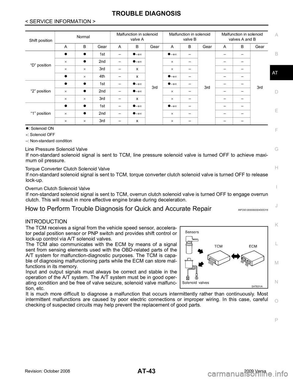
: Solenoid ON
× : Solenoid OFF
–: Non-standard condition
Line Pressure Solenoid Valve If non-standard solenoid signal is sent to TCM, line pre ssure solenoid valve is turned OFF to achieve maxi-
mum oil pressure.
Torque Converter Clutch Solenoid Valve If non-standard solenoid signal is sent to TCM, torque conv erter clutch solenoid valve is turned OFF to release
lock-up.
Overrun Clutch Solenoid Valve If non-standard solenoid signal is sent to TCM, overr un clutch solenoid valve is turned OFF to engage overrun
clutch. This will result in more effective engine brake during deceleration.
How to Perform Trouble Diagnosis for Quick and Accurate Repair INFOID:0000000004305316
INTRODUCTION The TCM receives a signal from the vehicle speed sensor, accelera-
tor pedal position sensor or PNP switch and provides shift control or
lock-up control via A/T solenoid valves.
The TCM also communicates with the ECM by means of a signal
sent from sensing elements used wit h the OBD-related parts of the
A/T system for malfunction-diagnostic purposes. The TCM is capa-
ble of diagnosing malfunctioning parts while the ECM can store mal-
functions in its memory.
Input and output signals must always be correct and stable in the
operation of the A/T system. T he A/T system must be in good oper-
ating condition and be free of valve seizure, solenoid valve malfunc-
tion, etc.
It is much more difficult to diagnose a malfunction t hat occurs intermittently rather than continuously. Most
intermittent malfunctions are caused by poor electric c onnections or improper wiring. In this case, careful
checking of suspected circuits may hel p prevent the replacement of good parts.
Shift position
Normal
Malfunction in solenoid
valve A Malfunction in solenoid
valve B Malfunction in solenoid
valves A and B
A B Gear A B Gear A B Gear A B Gear
“D” position z z
1st –z→×
3rd z
→× –
3rd – –
3rd
×
z2nd – z→× × – – –
× × 3rd – x ×– – –
z ×4th – x z→× – – –
“2” position z z
1st –z→× z→× – – –
× z2nd – z→× × – – –
× × 3rd – x ×– – –
“1” position z z
1st –z→× z→× – – –
× z2nd – z→× × – – –
× × 3rd – x ×– – –
Page 53 of 4331
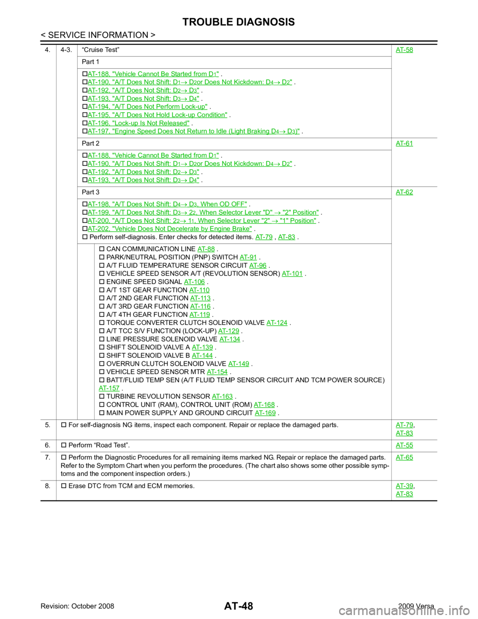
Part 1
† AT-188, " Vehicle Cannot Be Started from D .
† AT-190, " A/T Does Not Shift: D .
† AT-192, " A/T Does Not Shift: D .
† AT-193, " A/T Does Not Shift: D .
† AT-194, " A/T Does Not Perform Lock-up " .
† AT-195, " A/T Does Not Hold
Lock-up Condition " .
† AT-196, " Lock-up Is Not Released " .
† AT-197, " Engine Speed Does Not Return to Idle (Light Braking D " .
Part 2 AT-61Vehicle Cannot Be Started from D .
† AT-190, " A/T Does Not Shift: D .
† AT-192, " A/T Does Not Shift: D .
† AT-193, " A/T Does Not Shift: D .
Part 3 AT-62A/T Does Not Shift: D " .
† AT-199, " A/T Does Not Shift: D " .
† AT-200, " A/T Does Not Shift: 2 " .
† AT-202, " Vehicle Does Not Decelerate by Engine Brake " .
† Perform self-diagnosis. Enter checks for detected items. AT-79 ,
AT-83 .
† CAN COMMUNICATION LINE AT-88 .
† PARK/NEUTRAL POSITION (PNP) SWITCH AT-91 .
† A/T FLUID TEMPERATURE SENSOR CIRCUIT AT-96 .
† VEHICLE SPEED SENSOR A/T (REVOLUTION SENSOR) AT-101 .
† ENGINE SPEED SIGNAL AT-106 .
† A/T 1ST GEAR FUNCTION AT-110 .
† A/T 3RD GEAR FUNCTION AT-116 .
† A/T 4TH GEAR FUNCTION AT-119 .
† TORQUE CONVERTER CLUTCH SOLENOID VALVE AT-124 .
† A/T TCC S/V FUNCTION (LOCK-UP) AT-129 .
† LINE PRESSURE SOLENOID VALVE AT-134 .
† SHIFT SOLENOID VALVE A AT-139 .
† SHIFT SOLENOID VALVE B AT-144 .
† OVERRUN CLUTCH SOLENOID VALVE AT-149 .
† VEHICLE SPEED SENSOR MTR AT-154 .
† BATT/FLUID TEMP SEN (A/T FLUID TEMP SENSOR CIRCUIT AND TCM POWER SOURCE)
AT-157 .
† TURBINE REVOLUTION SENSOR AT-163 .
† CONTROL UNIT (RAM), CONTROL UNIT (ROM) AT-168 .
† MAIN POWER SUPPLY AND GROUND CIRCUIT AT-169 .
5. † For self-diagnosis NG items, inspect each component. Repair or replace the damaged parts. AT-79 ,
AT-83 6.
† Perform “Road Test”. AT-557.
† Perform the Diagnostic Procedures for all remaining items marked NG. Repair or replace the damaged parts.
Refer to the Symptom Chart when you perform the procedures. (The chart also shows some other possible symp-
toms and the component inspection orders.) AT-658.
† Erase DTC from TCM and ECM memories. AT-39 ,
AT-83
Page 84 of 4331
AT
N
O P
*1
: These terminals are connected to the data link connector.
*2 : These terminals are connected to the ECM.
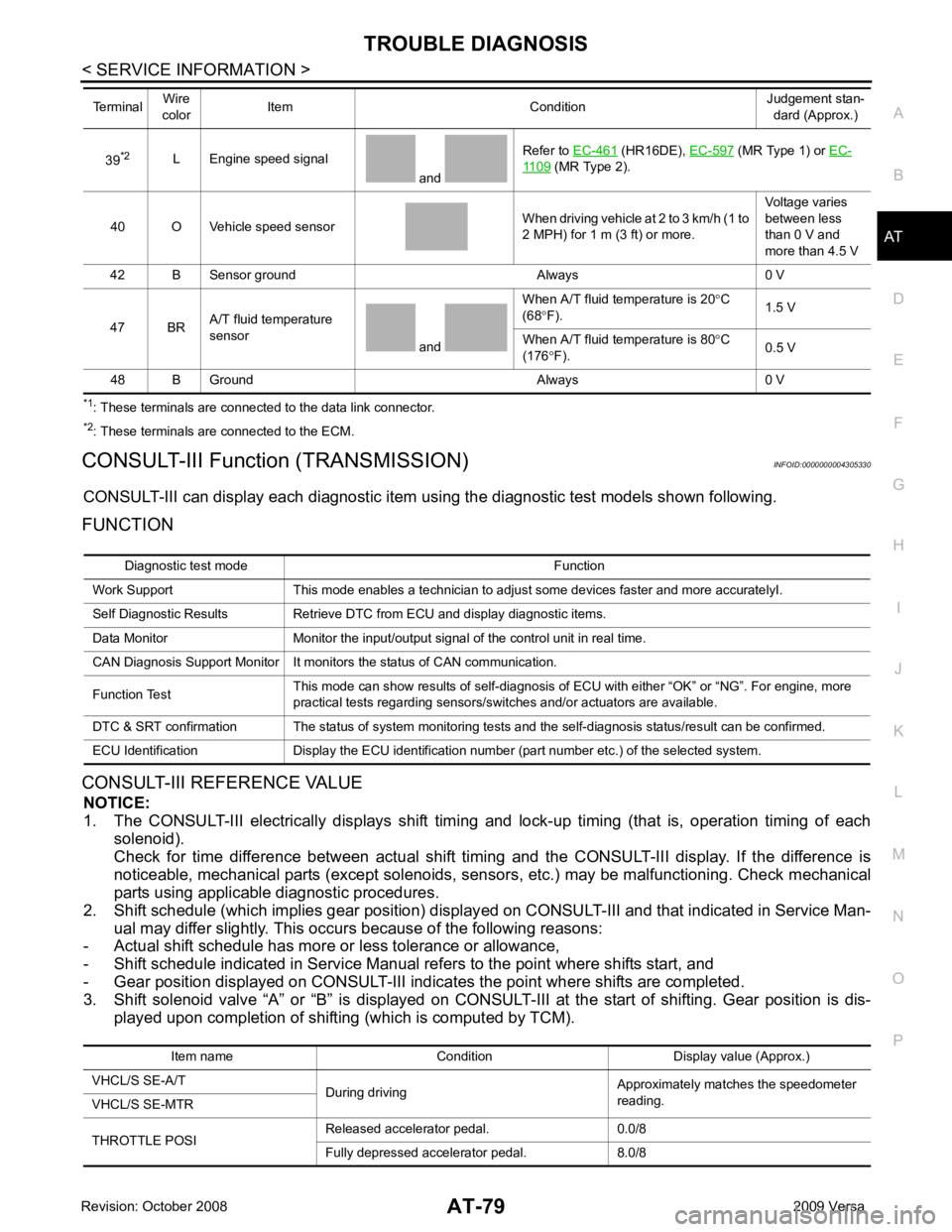
CONSULT-III Function (TRANSMISSION) INFOID:0000000004305330
CONSULT-III can display each diagnostic item using the diagnostic test models shown following.
FUNCTION
CONSULT-III REFERENCE VALUE NOTICE:
1. The CONSULT-III electrically displays shift timi ng and lock-up timing (that is, operation timing of each
solenoid).
Check for time difference between actual shift timi ng and the CONSULT-III display. If the difference is
noticeable, mechanical parts (except solenoids, sens ors, etc.) may be malfunctioning. Check mechanical
parts using applicable diagnostic procedures.
2. Shift schedule (which implies gear position) display ed on CONSULT-III and that indicated in Service Man-
ual may differ slightly. This occurs because of the following reasons:
- Actual shift schedule has more or less tolerance or allowance,
- Shift schedule indicated in Service Manual re fers to the point where shifts start, and
- Gear position displayed on CONSULT-III indicates the point where shifts are completed.
3. Shift solenoid valve “A” or “B” is displayed on CONSUL T-III at the start of shifting. Gear position is dis-
played upon completion of shifting (which is computed by TCM).
39
*2
L Engine speed signal
and Refer to
EC-461 (HR16DE),
EC-597 (MR Type 1) or
EC- 1109 (MR Type 2).
40 O Vehicle speed sensor When driving vehicle at 2 to 3 km/h (1 to
2 MPH) for 1 m (3 ft) or more. Voltage varies
between less
than 0 V and
more than 4.5 V
42 B Sensor ground Always 0 V
47 BR A/T fluid temperature
sensor and When A/T fluid temperature is 20
°C
(68 °F). 1.5 V
When A/T fluid temperature is 80 °C
(176 °F). 0.5 V
48 B Ground Always 0 V
Terminal
Wire
color Item Condition Judgement stan-
dard (Approx.) Diagnostic test mode Function
Work Support This mode enables a technician to adjust some devices faster and more accuratelyI.
Self Diagnostic Results Retrieve DTC from ECU and display diagnostic items.
Data Monitor Monitor the input/output signal of the control unit in real time.
CAN Diagnosis Support Monitor It monitors the status of CAN communication.
Function Test This mode can show results of self-diagnosis of ECU with either “OK” or “NG”. For engine, more
practical tests regarding sensors/switches and/or actuators are available.
DTC & SRT confirmation The status of system monitoring tests and the self-diagnosis status/result can be confirmed.
ECU Identification Display the ECU identification number (part number etc.) of the selected system. Item name Condition Display value (Approx.)
VHCL/S SE-A/T During driving Approximately matches the speedometer
reading.
VHCL/S SE-MTR
THROTTLE POSI Released accelerator pedal. 0.0/8
Fully depressed accelerator pedal. 8.0/8
Page 86 of 4331
AT
N
O P
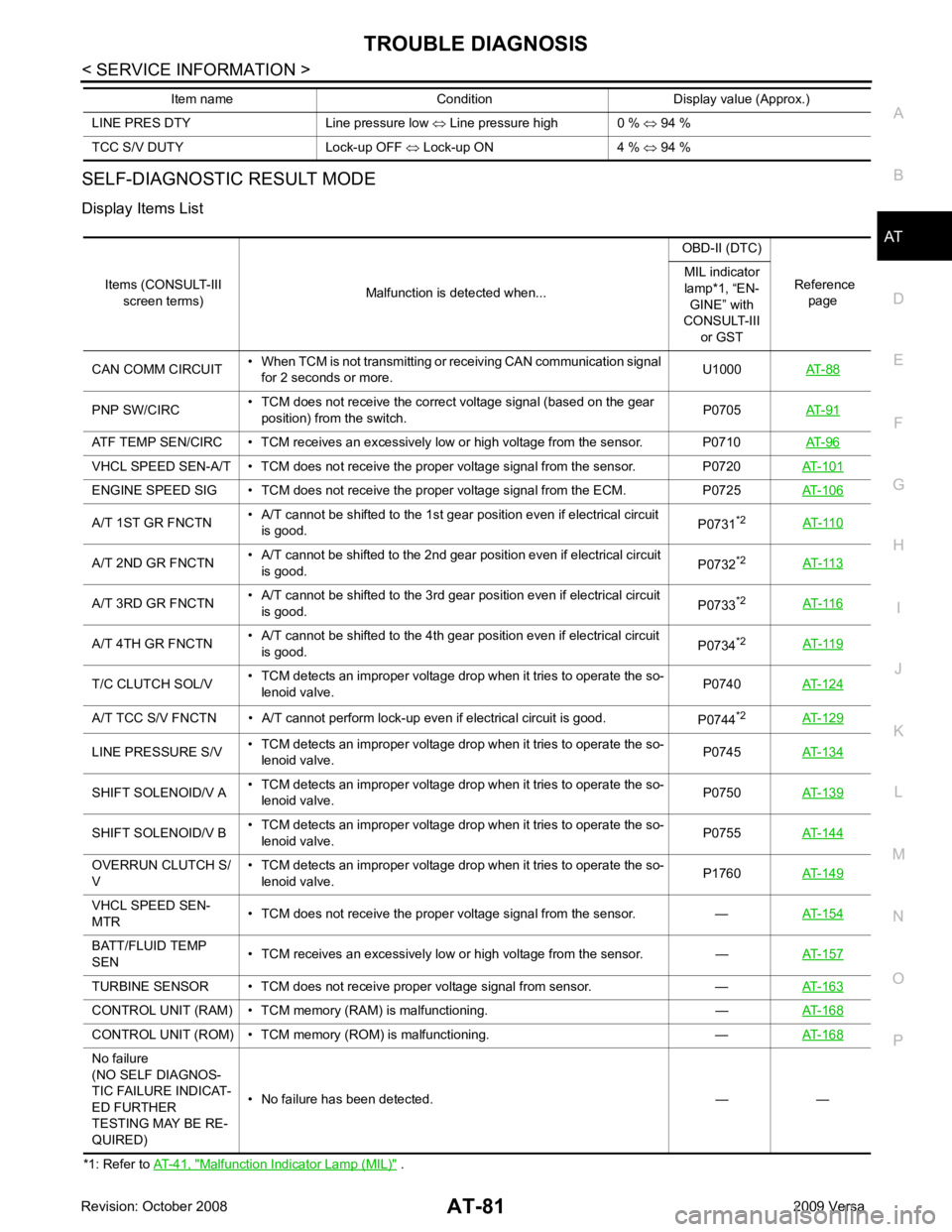
SELF-DIAGNOSTIC RESULT MODE
Display Items List
*1: Refer to AT-41, " Malfunction Indicator Lamp (MIL) " .
LINE PRES DTY Line pressure low
⇔ Line pressure high 0 % ⇔ 94 %
TCC S/V DUTY Lock-up OFF ⇔ Lock-up ON 4 % ⇔ 94 %
Item name Condition Display value (Approx.) Items (CONSULT-III
screen terms) Malfunction is detected when... OBD-II (DTC)
Reference page
MIL indicator
lamp*1, “EN- GINE” with
CONSULT-III
or GST
CAN COMM CIRCUIT • When TCM is not transmitting or receiving CAN communication signal
for 2 seconds or more. U1000
AT-88PNP SW/CIRC
• TCM does not receive the correct voltage signal (based on the gear
position) from the switch. P0705
AT-91ATF TEMP SEN/CIRC • TCM receives an excessively low or high voltage from the sensor. P0710
AT-96VHCL SPEED SEN-A/T • TCM does no
t receive the proper voltage signal from the sensor. P0720 AT-101ENGINE SPEED SIG • TCM does not
receive the proper voltage signal from the ECM. P0725 AT-106A/T 1ST GR FNCTN
• A/T cannot be shifted to the 1st gear
position even if electrical circuit
is good. P0731
*2
AT-110 A/T 2ND GR FNCTN
• A/T cannot be shifted to the 2nd gear position even if electrical circuit
is good. P0732
*2
AT-113 A/T 3RD GR FNCTN
• A/T cannot be shifted to the 3rd gear position even if electrical circuit
is good. P0733
*2
AT-116 A/T 4TH GR FNCTN
• A/T cannot be shifted to the 4th gear position even if electrical circuit
is good. P0734
*2
AT-119 T/C CLUTCH SOL/V
• TCM detects an improper voltage drop when it tries to operate the so-
lenoid valve. P0740
AT-124A/T TCC S/V FNCTN • A/T cannot perform lock-up even if electrical circuit is good.
P0744*2
AT-129 LINE PRESSURE S/V
• TCM detects an improper voltage drop when it tries to operate the so-
lenoid valve. P0745
AT-134SHIFT SOLENOID/V A
• TCM detects an improper voltage drop when it tries to operate the so-
lenoid valve. P0750
AT-139SHIFT SOLENOID/V B
• TCM detects an improper voltage drop when it tries to operate the so-
lenoid valve. P0755
AT-144OVERRUN CLUTCH S/
V • TCM detects an improper voltage drop when it tries to operate the so-
lenoid valve. P1760
AT-149VHCL SPEED SEN-
MTR • TCM does not receive the proper voltage signal from the sensor. —
AT-154BATT/FLUID TEMP
SEN • TCM receives an excessively low or high voltage from the sensor. —
AT-157TURBINE SENSOR • TCM does not receive proper voltage signal from sensor. —
AT-163CONTROL UNIT (RAM) • TC
M memory (RAM) is malfunctioning. — AT-168CONTROL UNIT (ROM) • TCM memory
(ROM) is malfunctioning. — AT-168No failure
(NO SELF DIAGNOS-
TIC FAILURE INDICAT-
ED FURTHER
TESTING MAY BE RE-
QUIRED) • No failure has been detected. — —
Page 118 of 4331

AT
N
O P
DTC P0732 A/T 2ND GEAR FUNCTION
Description INFOID:0000000004305373
• This malfunction will not be detected while the OD OFF indicator lamp is indicating another self-diagnosis malfunction.
• This malfunction is detected when the A/T does not shif t into second gear position as instructed by the TCM.
This is not caused by electrical malfunction (circuit s open or shorted) but by mechanical malfunction such as
control valve sticking, improper solenoid valve operation, etc.
On Board Diagnosis Logic INFOID:0000000004305374
• This is an OBD-II self-diagnostic item.
• Diagnostic trouble code “P0732 A/T 2ND GR FNCTN” with CONSULT-III is detected when A/T cannot be
shifted to the 2nd gear position even if electrical circuit is good.
• This diagnosis monitors actual gear position by checki ng the torque converter slip ratio calculated by TCM
as follows:
Torque converter slip ratio = A x C/B
A: Output shaft revolution signal from revolution sensor
B: Engine speed signal from ECM
C: Gear ratio determined as gear position which TCM supposes
If the actual gear position is higher than the position (2nd) supposed by TCM, the slip ratio will be more than
normal. In case the ratio exceeds the specif ied value, TCM judges this diagnosis malfunction.
This malfunction will be caused when shift solenoid valve B is stuck open.
• Gear positions supposed by TCM are as follows: In case of gear position with no malfunctions: 1, 2, 3 and 4 positions
In case of gear position with shift solenoid valve B stuck open: 4, 3*, 3 and 4 positions to each gear position
above
*: “P0732 A/T 2ND GR FNCTN” is detected.
Possible Cause INFOID:0000000004305375
• Shift solenoid valve B
• Each clutch
• Hydraulic control circuit
DTC Confirmation Procedure INFOID:0000000004305376
CAUTION:
• Always drive vehicle at a safe speed.
• If performing this “DTC Confirmation Procedure” again, always turn ignition switch OFF and wait at
least 10 seconds before continuing.
After the repair, perform the following procedure to confirm the malfunction is eliminated.
WITH CONSULT-III
1. Start engine and select “DATA MONITOR” m ode for “TRANSMISSION” with CONSULT-III.
2. Touch “START”.
3. Make sure that output voltage of A/T fluid temperature sensor is within the range below. FLUID TEMP SE: 0.4 - 1.5 V
If out of range, drive the vehicle to decrease the vo ltage (warm up the fluid) or stop engine to increase the
voltage (cool down the fluid).
4. Select “2ND GR FNCTN P0732” of “DTC & SR T CONFIRMATION” mode for “TRANSMISSION” with
CONSULT-III and touch “START”.
5. Accelerate vehicle to 45 to 50 km/h (28 to 31 MPH) under the following conditions and release the accel- erator pedal completely.
THROTTLE POSI: L ess than 1.0/8
SLCT LVR POSI: “D” position Gear position 1 2 3 4
Shift solenoid valve A ON (Closed) OFF (Open) OFF (Open) ON (Closed)
Shift solenoid valve B ON (Closed) ON (Closed) OFF (Open) OFF (Open)
Page 124 of 4331

AT
N
O P
DTC P0734 A/T 4TH GEAR FUNCTION
Description INFOID:0000000004305383
• This malfunction will not be detected while the OD OFF indicator lamp is indicating another self-diagnosis malfunction.
• This malfunction is detected when the A/T does not shif t into fourth gear position or the torque converter
clutch does not lock up as instructed by the TCM. This is not caused by electrical malfunction (circuits open
or shorted) but by mechanical malfunction such as c ontrol valve sticking, improper solenoid valve operation,
malfunctioning oil pump or torque converter clutch, etc.
CONSULT-III Reference Val ue in Data Monitor Mode INFOID:0000000004305384
Remarks: Specification data are reference values.
On Board Diagnosis Logic INFOID:0000000004305385
• This is an OBD-II self-diagnostic item.
• Diagnostic trouble code “P0734 A/T 4TH GR FNCTN” with CONSULT-III is detected when A/T cannot be
shifted to the 4th gear position even if electrical circuit is good.
• This diagnosis monitors actual gear position by checki ng the torque converter slip ratio calculated by TCM
as follows:
Torque converter slip ratio = A x C/B
A: Output shaft revolution signal from revolution sensor
B: Engine speed signal from ECM
C: Gear ratio determined as gear position which TCM supposes
If the actual gear position is much lower than the pos ition (4th) supposed by TCM, the slip ratio will be much
less than normal. In case the ratio does not reach t he specified value, TCM judges this diagnosis malfunc-
tion.
This malfunction will be caused when shift solenoid valve A is stuck open or shift solenoid valve B is stuck
closed.
• Gear positions supposed by TCM are as follows.
In case of gear position with no malfunctions: 1, 2, 3 and 4 positions
In case of gear position with shift solenoid valve A stuck open: 2, 2, 3 and 3* positions
In case of gear position with shift solenoid valve B stuck closed: 1, 2, 2 and 1* positions to each gear position
above
*: “P0734 A/T 4TH GR FNCTN” is detected.
Possible Cause INFOID:0000000004305386
• Shift solenoid valve A
• Shift solenoid valve B
• Line pressure solenoid valve
• Each clutch
• Hydraulic control circuit
DTC Confirmation Procedure INFOID:0000000004305387
CAUTION:
• Always drive vehicle at a safe speed.
• If performing this “DTC Confirmation Procedure” again, always turn ignition switch OFF and wait at
least 10 seconds before continuing.
After the repair, perform the following procedure to confirm the malfunction is eliminated. Gear position 1 2 3 4
Shift solenoid valve A ON (Closed) OFF (Open) OFF (Open) ON (Closed)
Shift solenoid valve B ON (Closed) ON (Closed) OFF (Open) OFF (Open) Item name Condition Display value (Approx.)
LINE PRES DTY Small throttle opening (Low line pressure)
⇔ Large
throttle opening (High line pressure) 0%
⇔ 94%