Fan blower NISSAN TIIDA 2009 Service Repair Manual
[x] Cancel search | Manufacturer: NISSAN, Model Year: 2009, Model line: TIIDA, Model: NISSAN TIIDA 2009Pages: 4331, PDF Size: 58.04 MB
Page 449 of 4331

BCS
N
O P
CAN Communication System Description INFOID:0000000004306834
Refer to LAN-8, " System Description " .
Panic alarm
• Key switch
• Keyfob IPDM E/R
Vehicle security system • All door switches
• Keyfob
• Door lock/unlock switch
• Trunk key cylinder switch (Se-
dan)
• Front door key cylinder switch LH • IPDM/ER
• Security indicator lamp
Battery saver control • Ignition switch
• Combination switch IPDM E/R
Headlamp Combination switch IPDM E/R
Tail lamp Combination switch IPDM E/R
Front fog lamp (with front fog lamps) Combination switch IPDM E/R
Turn signal lamp Combination switch • Turn signal lamp
• Combination meter
Hazard lamp Hazard switch • Turn signal lamp
• Combination meter
Room lamp timer • Key switch
• Keyfob
• Main power window and door lock/unlock switch
• Front door switch LH
• All door switch Interior room lamp
Back door switch signal (Hatchback) Back door lock assembly Luggage room lamp
Back door lock signal (Hatchback) Back door lock assembly Back door opener
Trunk lamp switch signal (Sedan) Trunk lamp switch and trunk re-
lease solenoid Luggage room lamp
Trunk lid opener signal (Sedan) Trunk lamp switch and trunk re-
lease solenoid Trunk lid opener
Key warning chime • Key switch
• Front door switch LH Combination meter (warning buzzer)
Light warning chime • Combination switch
• Key switch
• Front door switch LH Combination meter (warning buzzer)
Seat belt warning chime • Seat belt buckle switch LH
• Ignition switch Combination meter (warning buzzer)
Front wiper and washer system • Combination switch
• Ignition switch IPDM E/R
Rear window defogger Rear window defogger switch IPDM E/R
Rear wiper and washer system
(Hatchback) • Combination switch
• Ignition switch Rear wiper motor
A/C switch signal Front air control ECM
Blower fan switch signal Front air control ECM
A/C indicator signal Front air control A/C indicator
Low tire pressure warning system Remote keyless entry receiver Combination meter System Input Output
Page 1819 of 4331
EC
NP
O
*: Accelerator pedal position sensor 2 signal and throttle position sensor 2 signal are converted by ECM internally. Thus, they
differ from
ECM terminals voltage signal.
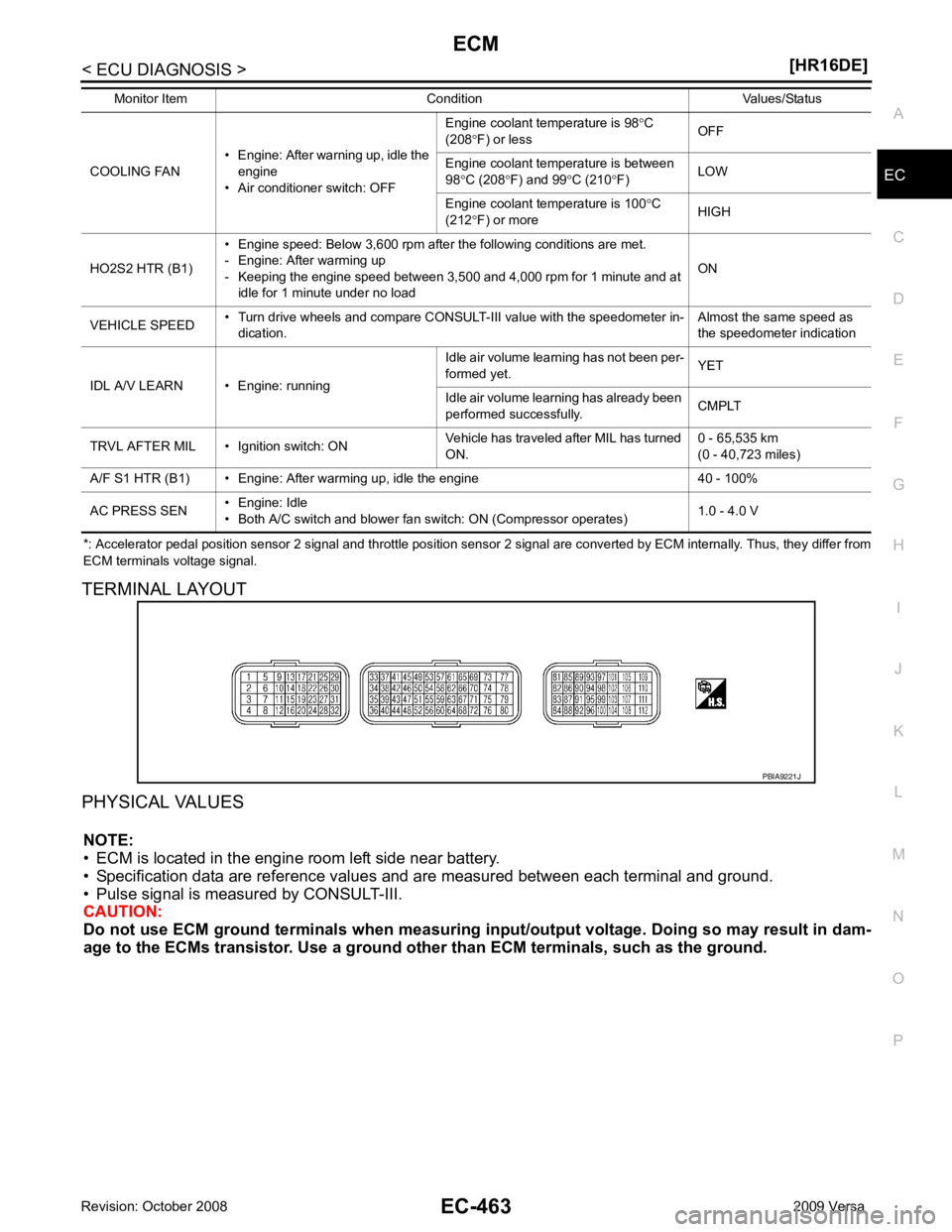
TERMINAL LAYOUT
PHYSICAL VALUES NOTE:
• ECM is located in the engine room left side near battery.
• Specification data are reference values and are measured between each terminal and ground.
• Pulse signal is measured by CONSULT-III.
CAUTION:
Do not use ECM ground terminals wh en measuring input/output voltage. Doing so may result in dam-
age to the ECMs transistor. Use a ground ot her than ECM terminals, such as the ground.
COOLING FAN
• Engine: After warning up, idle the
engine
• Air conditioner switch: OFF Engine coolant temperature is 98
°C
(208 °F) or less OFF
Engine coolant temperature is between
98 °C (208 °F) and 99 °C (210 °F) LOW
Engine coolant temperature is 100 °C
(212 °F) or more HIGH
HO2S2 HTR (B1) • Engine speed: Below 3,600 rpm after the following conditions are met.
- Engine: After warming up
- Keeping the engine speed between 3,500 and 4,000 rpm for 1 minute and at idle for 1 minute under no load ON
VEHICLE SPEED • Turn drive wheels and compare CONSULT-III value with the speedometer in-
dication. Almost the same speed as
the speedometer indication
IDL A/V LEARN • Engine: running Idle air volume learning has not been per-
formed yet. YET
Idle air volume learning has already been
performed successfully. CMPLT
TRVL AFTER MIL • Ignition switch: ON Vehicle has traveled after MIL has turned
ON. 0 - 65,535 km
(0 - 40,723 miles)
A/F S1 HTR (B1) • Engine: After warming up, idle the engine 40 - 100%
AC PRESS SEN • Engine: Idle
• Both A/C switch and blower fan switch: ON (Compressor operates) 1.0 - 4.0 V
Monitor Item Condition Values/Status
Page 1823 of 4331
![NISSAN TIIDA 2009 Service Repair Manual EC
NP
O
41 GR Refrigerant pressure sensor
[Engine is running]
• Warm-up condition
• Both A/C switch and blower fan switch: ON
(Compressor operates.) 1.0 - 4.0 V
42 V EVAP control system pres-
sur](/img/5/57398/w960_57398-1822.png "NISSAN TIIDA 2009 Service Repair Manual EC
NP
O
41 GR Refrigerant pressure sensor
[Engine is running]
• Warm-up condition
• Both A/C switch and blower fan switch: ON
(Compressor operates.) 1.0 - 4.0 V
42 V EVAP control system pres-
sur")
EC
NP
O
41 GR Refrigerant pressure sensor
[Engine is running]
• Warm-up condition
• Both A/C switch and blower fan switch: ON
(Compressor operates.) 1.0 - 4.0 V
42 V EVAP control system pres-
sure sensor [Ignition switch: ON]
Approximately 1.8 - 4.8 V
43 P Fuel tank temperature sen-
sor [Engine is running] Approximately 0 - 4.8 V
Output voltage varies with fuel
tank temperature
44 B Sensor ground
(Engine coolant temperature
sensor) [Engine is running]
• Warm-up condition
• Idle speed Approximately 0 V
45 G Mass air flow sensor [Engine is running]
• Warm-up condition
• Idle speed 0.9 - 1.3 V
[Engine is running]
• Warm-up condition
• Engine speed: 2,500 rpm 1.4 - 1.9 V
46 V Intake air temperature
sensor [Engine is running] Approximately 0 - 4.8 V
Output voltage varies with intake
air temperature.
48 BR Sensor ground
(Refrigerant pressure sen-
sor) [Engine is running]
• Warm-up condition
• Idle speed Approximately 0 V
49 W A/F sensor 1 [Engine is running]
• Warm-up condition
• Engine speed: 2,000 rpm Approximately 1.8 V
Output voltage varies with air fuel
ratio.
50 W Heated oxygen sensor 2 [Engine is running]
• Revving engine from idle to 3,000 rpm quickly after the following conditions are
met.
- Engine: After warming up
- Keeping the engine speed between 3,500
and 4,000 rpm for 1 minute and at idle for 1
minute under no load. 0 - 1.0 V
51 O Sensor ground
(EVAP control system pres-
sure sensor) [Engine is running]
• Warm-up condition
• Idle speed Approximately 0 V
52 LG Sensor ground
(Mass air flow sensor) [Engine is running]
• Warm-up condition
• Idle speed Approximately 0 V
53 B A/F sensor 1 [Ignition switch: ON]Approximately 2.2 V
55 O Sensor ground
(Intake air temperature sen-
sor) [Engine is running]
• Warm-up condition
• Idle speed Approximately 0 V
59 O Sensor ground
(Heated oxygen sensor 2) [Engine is running]
• Warm-up condition
• Idle speed Approximately 0 V
TERMI-
NAL
NO. WIRE
COLOR ITEM CONDITION DATA (DC Voltage)
Page 2046 of 4331

DTC Confirmation Proce-
dure " .
Engine coolant temperature has not risen enough to open the thermostat even though the engine has run long
enough. This is due to a leak in the seal or the thermostat stuck open.
DTC Confirmation Procedure INFOID:0000000004537164
WITH CONSULT-III
NOTE:
If DTC Confirmation Procedure has been previously conduc ted, always turn ignition switch OFF and wait at
least 10 seconds before conducting the next test.
TESTING CONDITION:
• For best results, perform at ambient temperature of –10 °C (14 °F) or higher.
• For best results, perform at en gine coolant temperature of –10 °C (14 °F) to 52 °C (126 °F).
• Before performing the following procedure, do not fill with the fuel.
1. Turn A/C switch OFF.
2. Turn blower fan switch OFF.
3. Turn ignition switch ON.
4. Select “COOLAN TEMP/S” in “DATA MONITOR” mode with CONSULT-III.
5. Check the indication of “COOLAN TEMP/S”. If it is below 52 °C (126 °F), go to following step.
If it is above 52 °C (126 °F), cool down the engine to less than 52 °C (126 °F). Then go to next steps.
6. Start engine and wait at idle for at least 30 minutes. If “COOLAN TEMP/S” increases to more than 71 °C (160 °F) within 30 minutes, turn ignition switch
OFF because the test result will be OK.
7. Check 1st trip DTC.
8. If 1st trip DTC is detected, go to EC-690, " Diagnosis Procedure " .
WITH GST
Follow the procedure “WITH CONSULT-III” above.
Diagnosis Procedure INFOID:0000000004537165Component Inspection " .
OK or NG OK >> GO TO 2.
NG >> Replace engine coolant temperature sensor. Removal and Installation " .
OK or NG OK >>
INSPECTION END
NG >> Replace thermostat. DTC No. Trouble diagnosis name DTC detecting condition Possible cause
P0128
0128 Thermostat function The engine coolant temperature does not
reach to specified temperature even though
the engine has run long enough. • Thermostat
• Leakage from sealing portion of thermostat
• Engine coolant temperature sensor
Page 2363 of 4331
![NISSAN TIIDA 2009 Service Repair Manual REFRIGERANT PRESSURE SENSOR
EC-1007
< SERVICE INFOMATION >
[MR TYPE 1] C
D E
F
G H
I
J
K L
M A EC
NP
O
Diagnosis Procedure
INFOID:00000000045375421.
CHECK REFRIGERANT PRESSURE SENSOR OVERALL FUNCTION](/img/5/57398/w960_57398-2362.png "NISSAN TIIDA 2009 Service Repair Manual REFRIGERANT PRESSURE SENSOR
EC-1007
< SERVICE INFOMATION >
[MR TYPE 1] C
D E
F
G H
I
J
K L
M A EC
NP
O
Diagnosis Procedure
INFOID:00000000045375421.
CHECK REFRIGERANT PRESSURE SENSOR OVERALL FUNCTION")
REFRIGERANT PRESSURE SENSOR
EC-1007
< SERVICE INFOMATION >
[MR TYPE 1] C
D E
F
G H
I
J
K L
M A EC
NP
O
Diagnosis Procedure
INFOID:00000000045375421.
CHECK REFRIGERANT PRESSURE SENSOR OVERALL FUNCTION
1. Start engine and warm it up to normal operating temperature.
2. Turn A/C switch and blower fan switch ON.
3. Check voltage between ECM terminal 41 and ground with CON- SULT-III or tester.
OK or NG OK >>
INSPECTION END
NG >> GO TO 2. 2.
CHECK GROUND CONNECTIONS
1. Turn A/C switch and blower fan switch OFF.
2. Stop engine and turn ignition switch OFF.
3. Loosen and retighten ground screw on the body. Refer to EC-632, " Ground Inspection " .
OK or NG OK >> GO TO 3.
NG >> Repair or replace ground connections. 3.
CHECK REFRIGERANT PRESSURE SE NSOR POWER SUPPLY CIRCUIT
TERMI-
NAL NO. WIRE
COLOR ITEM CONDITION DATA (DC Voltage)
41 GR Refrigerant pressure sensor [Engine is running]
• Warm-up condition
• Both A/C switch and blower fan switch: ON
(Compressor operates) 1.0 - 4.0V
48 BR Sensor ground
(Refrigerant pressure sensor) [Engine is running]
• Warm-up condition
• Idle speed Approximately 0V
74 W Sensor power supply
(Refrigerant pressure sensor) [Ignition switch: ON]
Approximately 5VVoltage: 1.0 - 4.0V
PBIA9574J
:
Vehicle front
1. Body ground E24 2. Engine ground F9 3. Engine ground F16
4. Body ground E15 BBIA0698E
Page 2564 of 4331

DTC Confirmation Proce-
dure " .
Engine coolant temperature has not risen enough to open the thermostat even though the engine has run long
enough. This is due to a leak in the seal or the thermostat stuck open.
DTC Confirmation Procedure INFOID:0000000004500050
WITH CONSULT-III
CAUTION:
Always drive vehicle at a safe speed.
NOTE:
If DTC Confirmation Procedure has been previously conduc ted, always turn ignition switch OFF and wait at
least 10 seconds before conducting the next test.
TESTING CONDITION:
• For best results, perform at ambient temperature of –10 °C (14 °F) or higher.
• For best results, perform at en gine coolant temperature of –10 °C (14 °F) to 53 °C (127 °F).
• Before performing the following procedure, do not fill with the fuel.
1. Turn A/C switch OFF.
2. Turn blower fan switch OFF.
3. Turn ignition switch ON.
4. Select “COOLAN TEMP/S” in “DATA MONITOR” mode with CONSULT-III.
5. Check the indication of “COOLAN TEMP/S”. If it is below 53 °C (127 °F), go to following step.
If it is above 53 °C (127 °F), cool down the engine to less than 53 °C (127 °F). Then go to next steps.
6. Start engine.
7. Drive vehicle for 10 consecutive minutes under the following conditions.
If “COOLAN TEMP/S” increases to more than 75 °C (167 °F) within 10 minutes, turn ignition switch
OFF because the test result will be OK.
8. Check 1st trip DTC.
9. If 1st trip DTC is detected, go to EC-1208, " Diagnosis Procedure " .
WITH GST
Follow the procedure “With CONSULT-III” above.
Diagnosis Procedure INFOID:0000000004500051Component Inspection " .
OK or NG OK >> GO TO 2.
NG >> Replace engine coolant temperature sensor. VHCL SPEED SE More than 56 km/h (35 MPH)
Page 2885 of 4331
![NISSAN TIIDA 2009 Service Repair Manual REFRIGERANT PRESSURE SENSOR
EC-1529
< SERVICE INFOMATION >
[MR TYPE 2] C
D E
F
G H
I
J
K L
M A EC
NP
O
Diagnosis Procedure
INFOID:00000000045004281.
CHECK REFRIGERANT PRESSURE SENSOR OVERALL FUNCTION](/img/5/57398/w960_57398-2884.png "NISSAN TIIDA 2009 Service Repair Manual REFRIGERANT PRESSURE SENSOR
EC-1529
< SERVICE INFOMATION >
[MR TYPE 2] C
D E
F
G H
I
J
K L
M A EC
NP
O
Diagnosis Procedure
INFOID:00000000045004281.
CHECK REFRIGERANT PRESSURE SENSOR OVERALL FUNCTION")
REFRIGERANT PRESSURE SENSOR
EC-1529
< SERVICE INFOMATION >
[MR TYPE 2] C
D E
F
G H
I
J
K L
M A EC
NP
O
Diagnosis Procedure
INFOID:00000000045004281.
CHECK REFRIGERANT PRESSURE SENSOR OVERALL FUNCTION
1. Start engine and warm it up to normal operating temperature.
2. Turn A/C switch and blower fan switch ON.
3. Check voltage between ECM terminal 41 and ground with CON- SULT-III or tester.
OK or NG OK >>
INSPECTION END
NG >> GO TO 2. 2.
CHECK GROUND CONNECTIONS
1. Turn A/C switch and blower fan switch OFF.
2. Stop engine and turn ignition switch OFF.
3. Loosen and retighten ground screw on the body. Refer to EC-1144, " Ground Inspection " .
OK or NG OK >> GO TO 3.
NG >> Repair or replace ground connections. 3.
CHECK REFRIGERANT PRESSURE SE NSOR POWER SUPPLY CIRCUIT
TERMI-
NAL NO. WIRE
COLOR ITEM CONDITION DATA (DC Voltage)
41 GR Refrigerant pressure sensor [Engine is running]
• Warm-up condition
• Both A/C switch and blower fan switch: ON
(Compressor operates) 1.0 - 4.0V
48 BR Sensor ground
(Refrigerant pressure sensor) [Engine is running]
• Warm-up condition
• Idle speed Approximately 0V
74 W Sensor power supply
(Refrigerant pressure sensor) [Ignition switch: ON]
Approximately 5VVoltage: 1.0 - 4.0V
PBIA9574J
:
Vehicle front
1. Body ground E24 2. Engine ground F9 3. Engine ground F16
4. Body ground E15 BBIA0698E
Page 3422 of 4331

LAN
N
O P
Engine status signal T R
Fuel consumption monitor signal T R
Malfunction indicator lamp signal T R
Wide open throttle position signal T R R
A/C switch signal R T
Blower fan motor switch signal R T
Buzzer output signal T R
T R
Day time running light request signal *3
T R
Door lock/unlock status signal T R
Door switch signal T R R R
Front wiper request signal T R
High beam request signal T R R
Horn chirp signal T R
Ignition switch signal T R
Low beam request signal T R
Position lights request signal T R R
Rear window defogger switch signal T R
Sleep/wake up signal R T
T R R R
Theft warning horn request signal T R
Tire pressure signal *4
T R
Trunk open/close status signal T R
Turn indicator signal T R
EPS operation signal R T
EPS warning lamp signal T R
Door lock/unlock/trunk open request signal R T
Hazard request signal R T
Ignition knob switch signal R T
KEY warning lamp signal T R
LOCK warning lamp signal T R
Panic alarm request signal R T
Fuel level sensor signal R T
Overdrive control switch signal T R R
P/N range signal T R
Stop lamp switch signal T R R
Vehicle speed signal R R R R T
R R R T R
R*5
T*5
ABS warning lamp signal R T
Brake warning lamp signal R T
A/T check indicator signal R T Signal name/Connecting unitECM
BCM EPS
I-KEY
M&AABS
TCM *1
TCM *2
IPDM-E
Page 3780 of 4331
MA
N
O P
CHASSIS AND BODY MAINTENANCE
IN-CABIN MICROFILTER
IN-CABIN MICROFILTER : Removal and Installation INFOID:0000000004683699
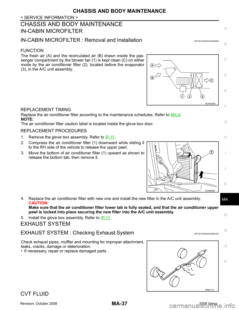
FUNCTION The fresh air (A) and the recirculated air (B) drawn inside the pas-
senger compartment by the blower fan (1) is kept clean (C) on either
mode by the air conditioner filter (2), located before the evaporator
(3), in the A/C unit assembly.
REPLACEMENT TIMING Replace the air conditioner filter according to the maintenance schedules. Refer to MA-9 .
NOTE:
The air conditioner filter caution label is located inside the glove box door.
REPLACEMENT PROCEDURES 1. Remove the glove box assembly. Refer to IP-11 .
2. Compress the air conditioner filter (1) downward while sliding it to the RH side of the vehicle to release the upper pawl.
3. Move the bottom of air conditioner filter (1) upward as shown to
release the bottom tab, then remove it.
4. Replace the air conditioner filter with new one and in stall the new filter in the A/C unit assembly.
CAUTION:
Make sure that the air cond itioner filter lower tab is fully seated , and that the air conditioner upper
pawl is locked into place securing the new filter into the A/C unit assembly.
5. Install the glove box assembly. Refer to IP-11 .
EXHAUST SYSTEM
EXHAUST SYSTEM : Chec king Exhaust System INFOID:0000000004683700
Check exhaust pipes, muffler and mounting for improper attachment,
leaks, cracks, damage or deterioration.
• If necessary, repair or replace damaged parts.
CVT FLUID SMA211A
Page 3886 of 4331

MTC
N
O P
CONTENTS
MANUAL AIR CONDITIONER
SERVICE INFORMATION .. ..........................3
PRECAUTIONS .............................................. .....3
Precaution for Supplemental Restraint System
(SRS) "AIR BAG" and "SEAT BELT PRE-TEN-
SIONER" ............................................................. ......
3
Precaution Necessary fo r Steering Wheel Rota-
tion After Battery Disconnect ............................... ......
3
Precaution for Procedure without Cowl Top Cover ......4
Precaution for Working with HFC-134a (R-134a) ......4
General Refrigerant Precaution .......................... ......4
Oil Precaution ...................................................... ......5
Precaution for Refrigeran t Connection ......................5
Precaution for Service of Compressor ................ ......7
Precaution for Service Equipment ....................... ......8
Precaution for Leak Detection Dye ..................... ......9
PREPARATION .............................................. ....11
HFC-134a (R-134a) Service Tool and Equipment ....11
Commercial Service Tool .................................... ....13
REFRIGERATION SYSTEM .......................... ....15
Refrigerant Cycle ................................................ ....15
Refrigerant System Protec tion ................................15
Component Part Location ................................... ....16
OIL .................................................................. ....17
Maintenance of Oil Quantity in Compressor ....... ....17
AIR CONDITIONER CONTROL ..................... ....19
Control Operation ................................................ ....19
Discharge Air Flow .............................................. ....20
System Description ............................................. ....20
TROUBLE DIAGNOSIS ................................. ....22
CONSULT-II Function (BCM) .............................. ....22
How to Perform Trouble Diagnosis for Quick and
Accurate Repair ........... ...........................................
22
Component Parts and Harness Connector Loca-
tion ...................................................................... ....
23
Schematic ........................................................... ....25
Wiring Diagram - Heater - ................................... ....26 Wiring Diagram - A/C,M - ....................................
....27
Operational Check ............................................... ....30
Mode Door ........................................................... ....31
Air Mix Door ......................................................... ....32
Intake Door .......................................................... ....33
Front Blower Motor Circuit .......................................33
Magnet Clutch Circuit (If Equipped) ..................... ....37
Insufficient Cooling .............................................. ....45
Insufficient Heating .............................................. ....52
Noise ................................................................... ....53
CONTROLLER .................................................. 55
Removal and Installation ..................................... ....55
Disassembly and Assembly ................................. ....56
THERMO CONTROL AMPLIFIER .................... 57
Removal and Installation ..................................... ....57
A/C UNIT ASSEMBLY ...................................... 58
Removal and Installation ..................................... ....58
Disassembly and Assembly ................................. ....60
BLOWER MOTOR ............................................ 62
Removal and Installation ..................................... ....62
INTAKE DOOR .................................................. 63
Intake Door Cable Adjustment ............................. ....63
AIR MIX DOOR ................................................. 64
Air Mix Door Cable Adjustment ........................... ....64
MODE DOOR .................................................... 65
Mode Door Cable Adjustment ............................. ....65
BLOWER FAN RESISTOR ............................... 66
Removal and Installation ..................................... ....66
HEATER CORE ................................................. 67
Removal and Installation ..................................... ....67
AIR CONDITIONER FILTER ............................. 68
Removal and Installation ..................................... ....68