brake rotor NISSAN TIIDA 2009 Service Repair Manual
[x] Cancel search | Manufacturer: NISSAN, Model Year: 2009, Model line: TIIDA, Model: NISSAN TIIDA 2009Pages: 4331, PDF Size: 58.04 MB
Page 803 of 4331
BR
N
O P
5. When the repair work is completed, return the ignition switch to the
″LOCK ″ position before connecting
the battery cables. (At this time, the steering lock mechanism will engage.)
6. Perform a self-diagnosis check of al l control units using CONSULT-III.
Precaution for Brake System INFOID:0000000004305887
• Refill using recommended brake fluid. Refer to MA-14 .
• Never reuse drained brake fluid.
• Be careful not to splash brake fluid on painted surfac e of body. If brake fluid is splashed on painted surfaces
of body immediately wipe it off with cloth and then wash it away with water.
• To clean or wash all parts of master cylinder, disc brake caliper and wheel cylinder, use new brake fluid.
• Never use mineral oils such as gasoline or kerosene. They will ruin rubber parts of the hydraulic system.
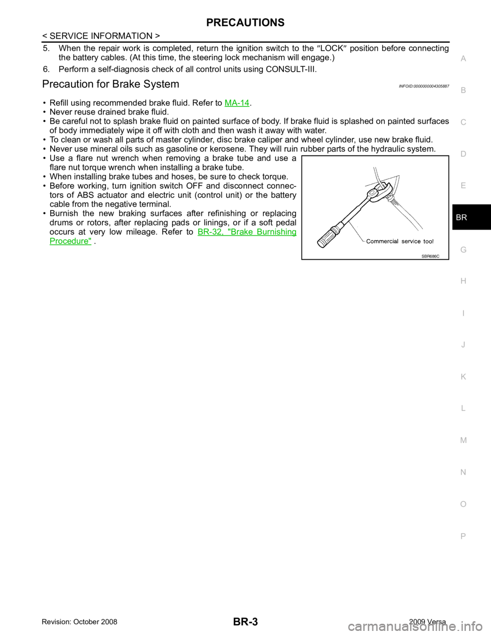
• Use a flare nut wrench when removing a brake tube and use a flare nut torque wrench when installing a brake tube.
• When installing brake tubes and hoses, be sure to check torque.
• Before working, turn igniti on switch OFF and disconnect connec-
tors of ABS actuator and electric unit (control unit) or the battery
cable from the negative terminal.
• Burnish the new braking surfaces after refinishing or replacing drums or rotors, after replacing p ads or linings, or if a soft pedal
occurs at very low mileage. Refer to BR-32, " Brake Burnishing
Procedure " .
Page 828 of 4331
Compo-
nent " .
5. Check brake for drag.
6. Install the front wheel and tire. Refer to WT-7, " Rotation " .
Removal and Installation of Brake Caliper Assembly INFOID:0000000004305912
REMOVAL
1. Remove front wheel and tire.
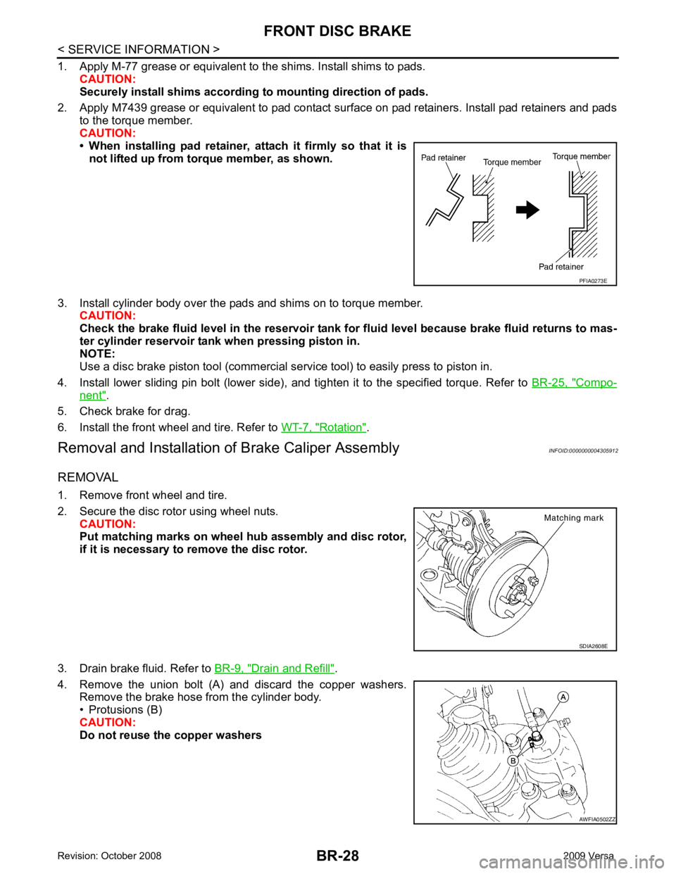
2. Secure the disc rotor using wheel nuts. CAUTION:
Put matching marks on wheel hub assembly and disc rotor,
if it is necessary to remove the disc rotor.
3. Drain brake fluid. Refer to BR-9, " Drain and Refill " .
4. Remove the union bolt (A) and discard the copper washers. Remove the brake hose from the cylinder body.
• Protusions (B)
CAUTION:
Do not reuse the copper washers AWFIA0502ZZ
Page 830 of 4331
BR-30< SERVICE INFORMATION >
FRONT DISC BRAKE
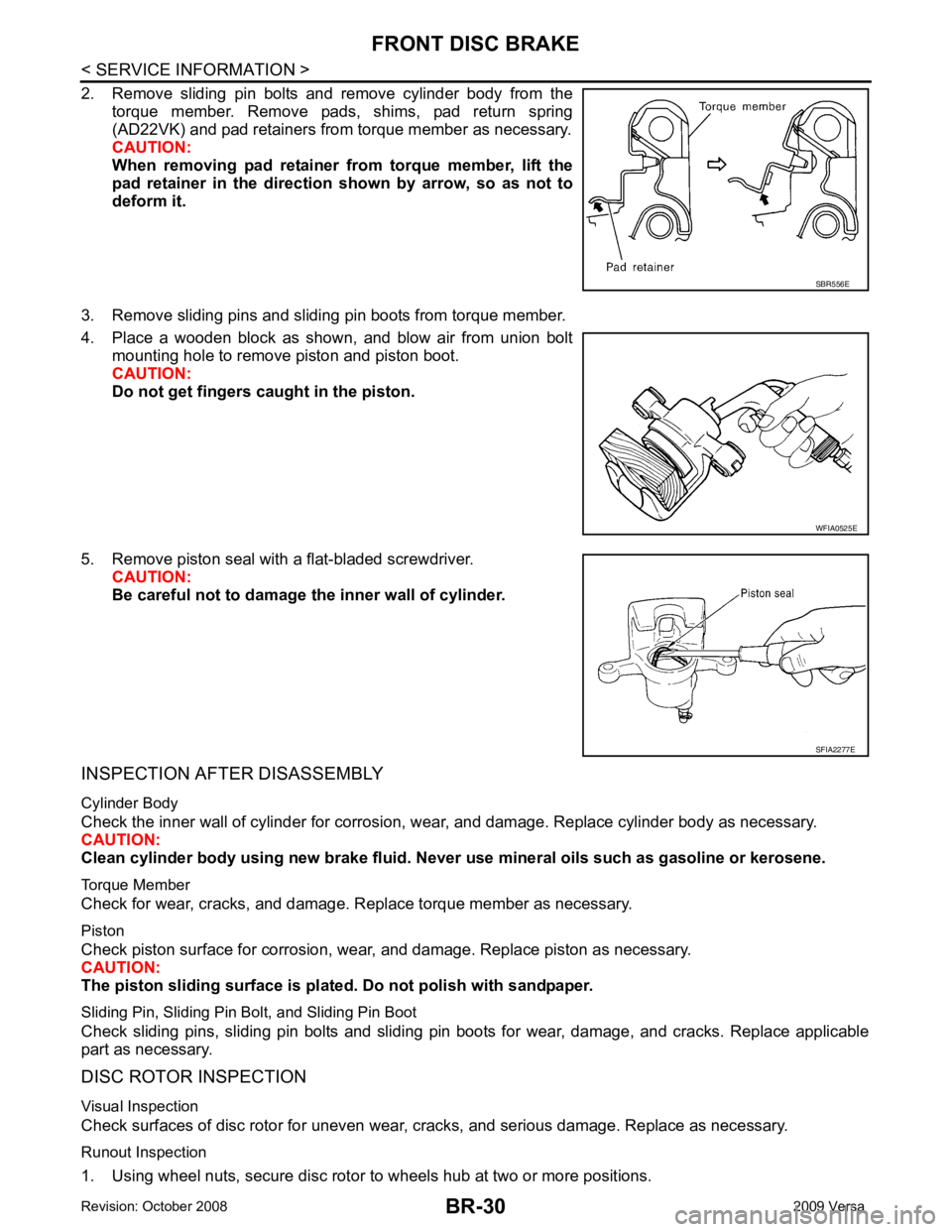
2. Remove sliding pin bolts and remove cylinder body from the torque member. Remove pads, shims, pad return spring
(AD22VK) and pad retainers from torque member as necessary.
CAUTION:
When removing pad retainer fr om torque member, lift the
pad retainer in the direction shown by arrow, so as not to
deform it.
3. Remove sliding pins and sliding pin boots from torque member.
4. Place a wooden block as shown, and blow air from union bolt mounting hole to remove piston and piston boot.
CAUTION:
Do not get fingers caught in the piston.
5. Remove piston seal with a flat-bladed screwdriver. CAUTION:
Be careful not to damage the inner wall of cylinder.
INSPECTION AFTER DISASSEMBLY
Cylinder Body
Check the inner wall of cylinder for corrosion, w ear, and damage. Replace cylinder body as necessary.
CAUTION:
Clean cylinder body using new brake fluid. Never use mineral oils such as gasoline or kerosene.
Torque Member
Check for wear, cracks, and damage. R eplace torque member as necessary.
Piston
Check piston surface for corrosion, wear, and damage. Replace piston as necessary.
CAUTION:
The piston sliding surface is plated . Do not polish with sandpaper.
Sliding Pin, Sliding Pin Bolt, and Sliding Pin Boot
Check sliding pins, sliding pin bolts and sliding pin boots for wear, damage, and cracks. Replace applicable
part as necessary.
DISC ROTOR INSPECTION
Visual Inspection
Check surfaces of disc rotor for uneven wear, cr acks, and serious damage. Replace as necessary.
Runout Inspection
1. Using wheel nuts, secure disc rotor to wheels hub at two or more positions. SBR556E
WFIA0525E
SFIA2277E
Page 831 of 4331
BR
N
O P
2. Using a dial indicator, check runout.
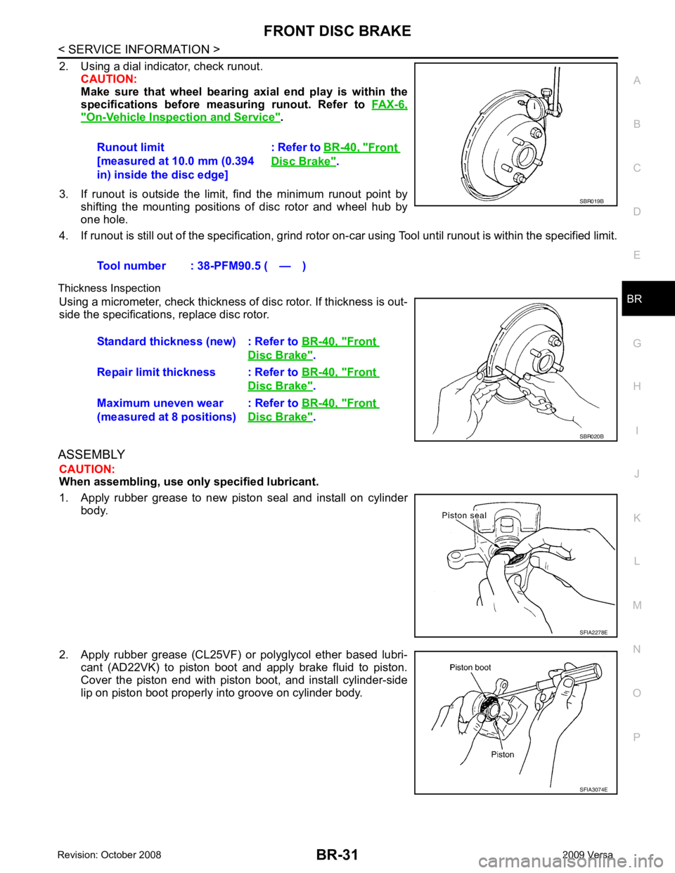
CAUTION:
Make sure that wheel bearing axi al end play is within the
specifications before measuring runout. Refer to FAX-6," On-Vehicle Inspection and Service " .
3. If runout is outside the limit, find the minimum runout point by shifting the mounting positions of disc rotor and wheel hub by
one hole.
4. If runout is still out of the specific ation, grind rotor on-car using Tool until runout is within the specified limit.
Thickness Inspection Using a micrometer, check thickness of disc rotor. If thickness is out-
side the specifications, replace disc rotor.
ASSEMBLY CAUTION:
When assembling, use only specified lubricant.
1. Apply rubber grease to new piston seal and install on cylinder body.
2. Apply rubber grease (CL25VF) or polyglycol ether based lubri- cant (AD22VK) to piston boot and apply brake fluid to piston.
Cover the piston end with piston boot, and install cylinder-side
lip on piston boot properly into groove on cylinder body. Runout limit
[measured at 10.0 mm (0.394
in) inside the disc edge] : Refer to
BR-40, " Front
Disc Brake " .
Tool number : 38-PFM90.5 ( — ) Front
Disc Brake " .
Repair limit thickness : Refer to BR-40, " Front
Disc Brake " .
Maximum uneven wear
(measured at 8 positions) : Refer to
BR-40, " Front
Disc Brake " .
Page 832 of 4331
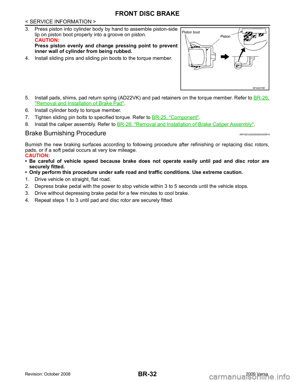
" Removal and Installation of Brake Pad " .
6. Install cylinder body to torque member.
7. Tighten sliding pin bolts to specified torque. Refer to BR-25, " Component " .
8. Install the caliper assembly. Refer to BR-28, " Removal and Installation of Brake Caliper Assembly " .
Brake Burnishing Procedure INFOID:0000000004305914
Burnish the new braking surfaces according to following procedure after refinishing or replacing disc rotors,
pads, or if a soft pedal occurs at very low mileage.
CAUTION:
• Be careful of vehicle speed because brake does not operate easily until pad and disc rotor are
securely fitted.
• Only perform this procedure under safe road and traffic conditions. Use extreme caution.
1. Drive vehicle on straight, flat road.
2. Depress brake pedal with the power to stop vehicl e within 3 to 5 seconds until the vehicle stops.
3. Drive without depressing brake pedal for a few minutes to cool brake.
4. Repeat steps 1 to 3 until pad and disc rotor are securely fitted.
Page 838 of 4331

Front brake Brake model CLZ25VF
Cylinder bore diameter 57.2 mm (2.252 in)
Pad
Length × width × thickness 125.6 mm
× 48.0 mm × 9.5 mm
(4.945 in × 1.890 in × 0.374 in)
Rotor outer diameter × thickness 280 mm × 24.0 mm (11.02 in × 0.945 in)
Rear brake Brake model LT23 Cylinder bore diameter 19.06 mm (0.750 in)
Drum inner diameter 228.6 mm (9.000 in)
Master cylinder Cylinder bore diameter 23.81 ± 0.015 mm (0.937 ± 0.001 in)
Brake booster Booster model C255 Diaphragm diameter 255 mm (10.04 in)
Recommended brake fluid DOT 3
Page 840 of 4331
BR-40< SERVICE INFORMATION >
SERVICE DATA AND SPECIFICATIONS (SDS)
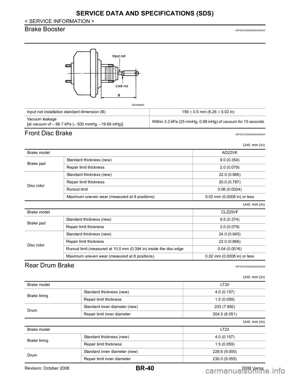
Brake Booster INFOID:0000000004305922
Front Disc Brake INFOID:0000000004305923
Unit: mm (in)
Unit: mm (in)
Rear Drum Brake INFOID:0000000004305924
Unit: mm (in)
Unit: mm (in)
Input rod installation standard dimension (B) 159
± 0.5 mm (6.26 ± 0.02 in)
Vacuum leakage
[at vacuum of – 66.7 kPa (– 500 mmHg, –19.69 inHg)] Within 3.3 kPa (25 mmHg, 0.98 inHg) of vacuum for 15 seconds SGIA0060E
Brake model AD22VK
Brake pad Standard thickness (new) 9.0 (0.354)
Repair limit thickness 2.0 (0.079)
Disc rotor Standard thickness (new) 22.0 (0.866)
Repair limit thickness 20.0 (0.787)
Runout limit 0.06 (0.0024)
Maximum uneven wear (measured at 8 positions) 0.02 mm (0.0008 in) or less Brake model
CLZ25VF
Brake pad Standard thickness (new) 9.5 (0.374)
Repair limit thickness 2.0 (0.079)
Disc rotor Standard thickness (new) 24.0 (0.945)
Repair limit thickness 22.0 (0.866)
Runout limit (measured at 10.0 mm (0.394 in) inside the disc edge 0.04 (0.0016)
Maximum uneven wear (measured at 8 positions) 0.02 mm (0.0008 in) or less Brake model
LT20
Brake lining Standard thickness
(new) 4.0 (0.157)
Repair limit thickness 1.5 (0.059)
Drum Standard inner diameter (new) 203 (7.992)
Repair limit inner diameter 204.5 (8.051) Brake model
LT23
Brake lining Standard thickness (new) 4.0 (0.157)
Repair limit thickness 1.5 (0.059)
Drum Standard inner diameter (new) 228.6 (9.000)
Repair limit inner diameter 230.0 (9.055)
Page 841 of 4331

BRC
N
O P
CONTENTS
BRAKE CONTROL SYSTEM
ABS
SERVICE INFORMATION .. ..........................
2
PRECAUTIONS .............................................. .....2
Precaution for Supplemental Restraint System
(SRS) "AIR BAG" and "SEAT BELT PRE-TEN-
SIONER" ............................................................. ......
2
Precaution for Brake System .............................. ......2
Precaution for Brake Cont rol .....................................3
Precaution for CAN System ................................ ......3
PREPARATION .............................................. .....4
Special Service Tool ........................................... ......4
Commercial Service Tool .................................... ......4
SYSTEM DESCRIPTION ................................ .....5
System Component ............................................. ......5
ABS Function ...................................................... ......5
EBD Function ...................................................... ......5
Fail-Safe Function ............................................... ......5
Hydraulic Circuit Diagram .........................................6
CAN COMMUNICATION ................................ .....7
System Description ............................................. ......7
TROUBLE DIAGNOSIS ................................. .....8
How to Perform Trouble Diagnosis for Quick and
Accurate Repair ........... .............................................
8
Component Parts and Harness Connector Loca-
tion ...................................................................... ....
11
Schematic ........................................................... ....12
Wiring Diagram - ABS - ... ........................................13 Basic Inspection ..................................................
....16
Warning Lamp and Indicator Timing .................... ....17
Control Unit Input/Output Signal Standard .......... ....17
CONSULT-III Function ( ABS) ..................................18
TROUBLE DIAGNOSIS FOR SELF-DIAG-
NOSTIC ITEMS ................................................. 24
Wheel Sensor System ......................................... ....24
ABS Control Unit Inspection ................................ ....25
Solenoid Valve System Inspection ...................... ....25
Actuator Motor, Motor Re lay, and Circuit Inspec-
tion ....................................................................... ....
26
ABS Control Unit Power and Ground Systems In-
spection ............................................................... ....
27
CAN Communication System Inspection ............. ....28
TROUBLE DIAGNOSES FOR SYMPTOMS ..... 29
ABS Works Frequently ........................................ ....29
Unexpected Pedal Action .................................... ....29
Long Stopping Distance ...................................... ....30
ABS Does Not Work ............................................ ....30
Pedal Vibration or ABS Op eration Noise .................30
WHEEL SENSORS ........................................... 32
Removal and Installation ..................................... ....32
SENSOR ROTOR .............................................. 34
Removal and Installation ..................................... ....34
ACTUATOR AND ELECTRIC UNIT (ASSEM-
BLY) .................................................................. 35
Removal and Installation ..................................... ....35
Page 842 of 4331
![NISSAN TIIDA 2009 Service Repair Manual BRC-2< SERVICE INFORMATION >
[ABS]
PRECAUTIONS
SERVICE INFORMATION
PRECAUTIONS
Precaution for Supplemental Restraint Syst em (SRS) "AIR BAG" and "SEAT BELT
PRE-TENSIONER" INFOID:0000000004784402
The](/img/5/57398/w960_57398-841.png "NISSAN TIIDA 2009 Service Repair Manual BRC-2< SERVICE INFORMATION >
[ABS]
PRECAUTIONS
SERVICE INFORMATION
PRECAUTIONS
Precaution for Supplemental Restraint Syst em (SRS) \"AIR BAG\" and \"SEAT BELT
PRE-TENSIONER\" INFOID:0000000004784402
The")
BRC-2< SERVICE INFORMATION >
[ABS]
PRECAUTIONS
SERVICE INFORMATION
PRECAUTIONS
Precaution for Supplemental Restraint Syst em (SRS) "AIR BAG" and "SEAT BELT
PRE-TENSIONER" INFOID:0000000004784402
The Supplemental Restraint System such as “A IR BAG” and “SEAT BELT PRE-TENSIONER”, used along
with a front seat belt, helps to reduce the risk or severi ty of injury to the driver and front passenger for certain
types of collision. This system includes seat belt switch inputs and dual stage front air bag modules. The SRS
system uses the seat belt switches to determine the front air bag deployment, and may only deploy one front
air bag, depending on the severity of a collision and w hether the front occupants are belted or unbelted.
Information necessary to service the system safely is included in the SRS and SB section of this Service Man-
ual.
WARNING:
• To avoid rendering the SRS inopera tive, which could increase the risk of personal injury or death in
the event of a collision which would result in air bag inflation, all maintenance must be performed by
an authorized NISS AN/INFINITI dealer.
• Improper maintenance, including incorrect removal and installation of the SRS can lead to personal
injury caused by unintent ional activation of the system. For re moval of Spiral Cable and Air Bag
Module, see the SRS section.
• Do not use electrical test equipmen t on any circuit related to the SRS unless instructed to in this
Service Manual. SRS wiring harn esses can be identified by yellow and/or orange harnesses or har-
ness connectors.
PRECAUTIONS WHEN USING POWER TOOLS (AIR OR ELECTRIC) AND HAMMERS
WARNING:
• When working near the Airbag Diagnosis Sensor Unit or other Airbag System sensors with the Igni-
tion ON or engine running, DO NOT use air or electri c power tools or strike near the sensor(s) with a
hammer. Heavy vibration could activate the sensor( s) and deploy the air bag(s), possibly causing
serious injury.
• When using air or electric power tools or hammers , always switch the Ignition OFF, disconnect the
battery, and wait at least 3 minu tes before performing any service.
Precaution for Brake System INFOID:0000000004307251
CAUTION:
• Refer to MA-14 for recommended brake fluid.
• Never reuse drained brake fluid.
• Be careful not to splash brake fluid on painted areas; it may cause paint damage. If brake fluid is
splashed on painted areas, wash it away with water immediately.
• To clean or wash all parts of master cylin der and disc brake caliper, use clean brake fluid.
• Never use mineral oils such as gasoline or kerosene. They will ruin rubber parts of the hydraulic sys-
tem.
• Use flare nut wrench when re moving and installing brake
tube.
• If a brake fluid leak is found, the part must be disassembled
without fail. Then it has to be replaced with a new one if a
defect exists.
• Turn the ignition switch OFF an d remove the connector of the
ABS actuator and electric unit (c ontrol unit) or the battery ter-
minal before performing the work.
• Always torque brake lines when installing.
• Burnish the brake contact surf aces after refinishing or replac-
ing rotors, after replacing pads, or if a soft pedal occurs at
very low mileage. Refer to BR-32, " Brake Burnishing Proce-
dure " .
WARNING:
• Clean brake pads and shoes with a waste cloth, then wipe with a dust collector. SBR686C
Page 3202 of 4331
FAX
N
O P
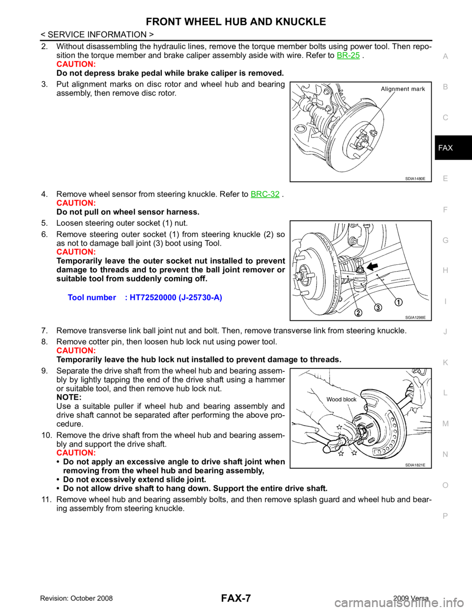
2. Without disassembling the hydraulic lines, remove the torque member bolts using power tool. Then repo-
sition the torque member and brake caliper assembly aside with wire. Refer to BR-25 .
CAUTION:
Do not depress brake pedal while brake caliper is removed.
3. Put alignment marks on disc rotor and wheel hub and bearing assembly, then remove disc rotor.
4. Remove wheel sensor from steering knuckle. Refer to BRC-32 .
CAUTION:
Do not pull on wheel sensor harness.
5. Loosen steering outer socket (1) nut.
6. Remove steering outer socket (1) from steering knuckle (2) so as not to damage ball joint (3) boot using Tool.
CAUTION:
Temporarily leave the outer so cket nut installed to prevent
damage to threads and to pr event the ball joint remover or
suitable tool from suddenly coming off.
7. Remove transverse link ball joint nut and bolt. Then, remove transverse link from steering knuckle.
8. Remove cotter pin, then loosen hub lock nut using power tool. CAUTION:
Temporarily leave the hub lock nut inst alled to prevent damage to threads.
9. Separate the drive shaft from the wheel hub and bearing assem- bly by lightly tapping the end of the drive shaft using a hammer
or suitable tool, and then remove hub lock nut.
NOTE:
Use a suitable puller if wheel hub and bearing assembly and
drive shaft cannot be separated after performing the above pro-
cedure.
10. Remove the drive shaft from the wheel hub and bearing assem- bly and support the drive shaft.
CAUTION:
• Do not apply an excessive angle to drive shaft joint when
removing from the wheel hub and bearing assembly,
• Do not excessively extend slide joint.
• Do not allow drive shaft to hang do wn. Support the entire drive shaft.
11. Remove wheel hub and bearing assembly bolts, and then remove splash guard and wheel hub and bear- ing assembly from steering knuckle.