flat tire NISSAN TIIDA 2009 Service Repair Manual
[x] Cancel search | Manufacturer: NISSAN, Model Year: 2009, Model line: TIIDA, Model: NISSAN TIIDA 2009Pages: 4331, PDF Size: 58.04 MB
Page 3241 of 4331
FSU
N
O P
FRONT SUSPENSION ASSEMBLY
On-Vehicle Inspection and Service INFOID:0000000004305863
Make sure the mounting conditions (looseness, back lash) of each component and component conditions
(wear, damage) are normal.
INSPECTION OF LOWER BALL JOINT END PLAY 1. Set front wheels in a straight-ahead position. Do not depress brake pedal.
2. Place an iron bar or similar tool bet ween transverse link and steering knuckle.
3. Measure axial end play by prying it up and down.
CAUTION:
Be careful not to damage ball joint boot. Do not damage the installation position by applying
excessive force.
STRUT INSPECTION Check for oil leakage, damage and replace as necessary.
Wheel Alignment Inspection INFOID:0000000004305864
PRELIMINARY INSPECTION WARNING:
Always adjust the alignment with the vehicle on a flat surface.
NOTE:
If alignment is out of specification, inspect and r eplace any damaged or worn rear suspension parts before
making any adjustments.
1. Check and adjust the wheel alignment with the vehicle under unladen conditions. “Unladen conditions”
means that the fuel, coolant, and lubricant are full; and that the spare tire, jack, hand tools and mats are in
their designated positions.
2. Check the tires for incorrect air pressure and excessive wear.
3. Check the wheels for run out and damage. Refer to WT-6, " Inspection " .
4. Check the wheel bearing axial end play. Refer to FAX-6, " On-Vehicle Inspection and Service " .
5. Check the shock absorbers for leaks or damage.
6. Check each mounting point of the suspension components for any excessive looseness or damage.
7. Check each link, arm, and the suspension member for any damage.
8. Check the vehicle height. Refer to FSU-19, " Wheelarch Height (Unladen*) " .
GENERAL INFORMATION AND RECOMMENDATIONS 1. A Four-Wheel Thrust Alignment should be performed. • This type of alignment is re commended for any NISSAN vehicle.
• The four-wheel “thrust” process helps ensure that the vehicle is properly aligned and the steering wheel
is centered.
• The alignment machine itself should be ca pable of accepting any NISSAN vehicle.
• The alignment machine should be checked to ensure that it is level.
2. Make sure the alignment machine is properly calibrated. • Your alignment machine should be regularly calib rated in order to give correct information.
• Check with the manufacturer of your specific a lignment machine for their recommended Service/Cali-
bration Schedule.
THE ALIGNMENT PROCESS IMPORTANT: Use only the alignment specifications listed in this Service Manual. Refer to FSU-17, " Wheel
Alignment (Unladen*) " .
1. When displaying the alignment settings, many alignm ent machines use “indicators”: (Green/red, plus or
minus, Go/No Go). Do NOT use these indicators.
• The alignment specifications programmed into your alignment machine that operate these indicators
may not be correct. Axial end play : 0 mm (0 in)
Page 3627 of 4331
LT
N
O P
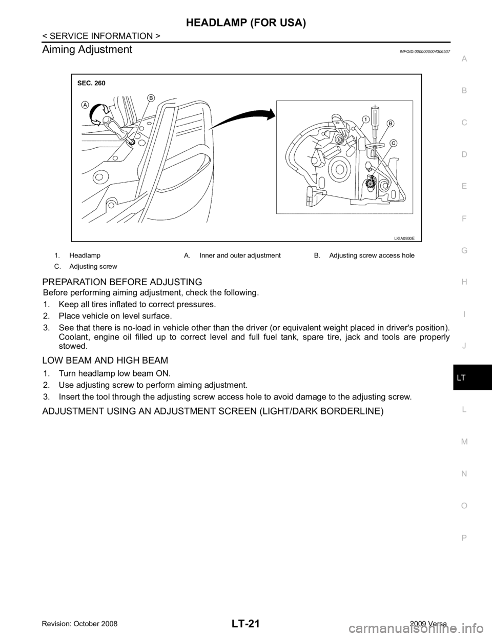
Aiming Adjustment
INFOID:0000000004306537
PREPARATION BEFORE ADJUSTING Before performing aiming adjustment, check the following.
1. Keep all tires inflated to correct pressures.
2. Place vehicle on level surface.
3. See that there is no-load in vehicle other than the driv er (or equivalent weight placed in driver's position).
Coolant, engine oil filled up to correct level and full fuel tank, spare tire, jack and tools are properly
stowed.
LOW BEAM AND HIGH BEAM 1. Turn headlamp low beam ON.
2. Use adjusting screw to perform aiming adjustment.
3. Insert the tool through the adjusting screw acce ss hole to avoid damage to the adjusting screw.
ADJUSTMENT USING AN ADJUSTMENT SCREEN (LIGHT/DARK BORDERLINE) 1. Headlamp A. Inner and outer adjustment B. Adjusting screw access hole
C. Adjusting screw
Page 3641 of 4331
HEADLAMP (FOR CANADA) - DA
YTIME LIGHT SYSTEM -
LT-35
< SERVICE INFORMATION >
C
D E
F
G H
I
J
L
M A
B LT
N
O P
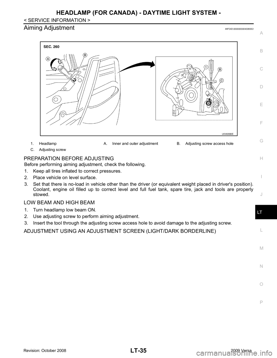
Aiming Adjustment
INFOID:0000000004306553
PREPARATION BEFORE ADJUSTING Before performing aiming adjustment, check the following.
1. Keep all tires inflated to correct pressures.
2. Place vehicle on level surface.
3. Set that there is no-load in vehicle other than the driv er (or equivalent weight placed in driver's position).
Coolant, engine oil filled up to correct level and full fuel tank, spare tire, jack and tools are properly
stowed.
LOW BEAM AND HIGH BEAM 1. Turn headlamp low beam ON.
2. Use adjusting screw to perform aiming adjustment.
3. Insert the tool through the adjusting screw a ccess hole to avoid damage to the adjusting screw.
ADJUSTMENT USING AN ADJUSTMENT SCREEN (LIGHT/DARK BORDERLINE) 1. Headlamp A. Inner and outer adjustment B. Adjusting screw access hole
C. Adjusting screw LKIA0930E
Page 3652 of 4331
OK >> Replace IPDM E/R. Refer to
PG-27, " Removal and
Installation of IPDM E/R " .
NG >> Repair harness or connector.
Aiming Adjustment INFOID:0000000004306569
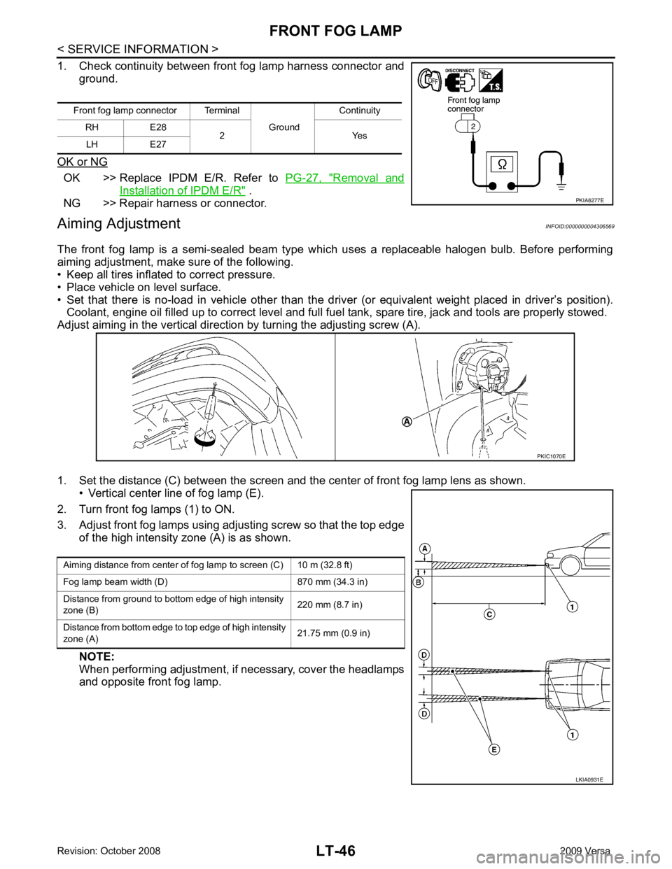
The front fog lamp is a semi-sealed beam type which uses a replaceable halogen bulb. Before performing
aiming adjustment, make sure of the following.
• Keep all tires inflated to correct pressure.
• Place vehicle on level surface.
• Set that there is no-load in vehicle other than the driv er (or equivalent weight placed in driver’s position).
Coolant, engine oil filled up to correct level and full fuel tank, spare tire, jack and tools are properly stowed.
Adjust aiming in the vertical direct ion by turning the adjusting screw (A).
1. Set the distance (C) between the screen and the center of front fog lamp lens as shown. • Vertical center line of fog lamp (E).
2. Turn front fog lamps (1) to ON.
3. Adjust front fog lamps using adjusting screw so that the top edge of the high intensity zone (A) is as shown.
NOTE:
When performing adjustment, if necessary, cover the headlamps
and opposite front fog lamp.
Front fog lamp connector Terminal
Ground Continuity
RH E28 2 Yes
LH E27
Page 4118 of 4331
RSU
N
O P
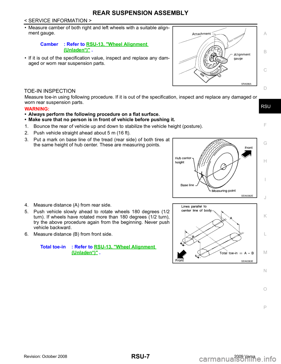
• Measure camber of both right and left wheels with a suitable align-
ment gauge.
• If it is out of the specificati on value, inspect and replace any dam-
aged or worn rear suspension parts.
TOE-IN INSPECTION Measure toe-in using following procedure. If it is out of the specification, inspect and replace any damaged or
worn rear suspension parts.
WARNING:
• Always perform the following procedure on a flat surface.
• Make sure that no person is in fron t of vehicle before pushing it.
1. Bounce the rear of vehicle up and down to stabilize the vehicle height (posture).
2. Push vehicle straight ahead about 5 m (16 ft).
3. Put a mark on base line of the tread (rear side) of both tires at the same height of hub center. These are measuring points.
4. Measure distance (A) from rear side.
5. Push vehicle slowly ahead to rotate wheels 180 degrees (1/2 turn). If wheels have rotated more than 180 degrees (1/2 turn),
try the above procedure again from the beginning. Never push
vehicle backward.
6. Measure distance (B) from front side. Camber : Refer to
RSU-13, " Wheel Alignment
(Unladen*) " .
SEIA0362E
Wheel Alignment
(Unladen*) " .
Page 4120 of 4331
RSU
N
O P
SHOCK ABSORBER
Removal and Installation INFOID:0000000004305881
REMOVAL 1. Remove wheel and tire using power tool.
2. Remove wheel sensor from wheel hub and bearing assembly and rear suspension beam. Refer to BRC-32 .
CAUTION:
Do not pull on wheel sensor harness.
3. Remove shock absorber mask from trunk side fini sher using a flat-bladed screwdriver. Refer to EI-53 .
CAUTION:
Wrap the tip of a screwdriver with cl oth to avoid damaging components.
4. Set jack under rear suspension beam.
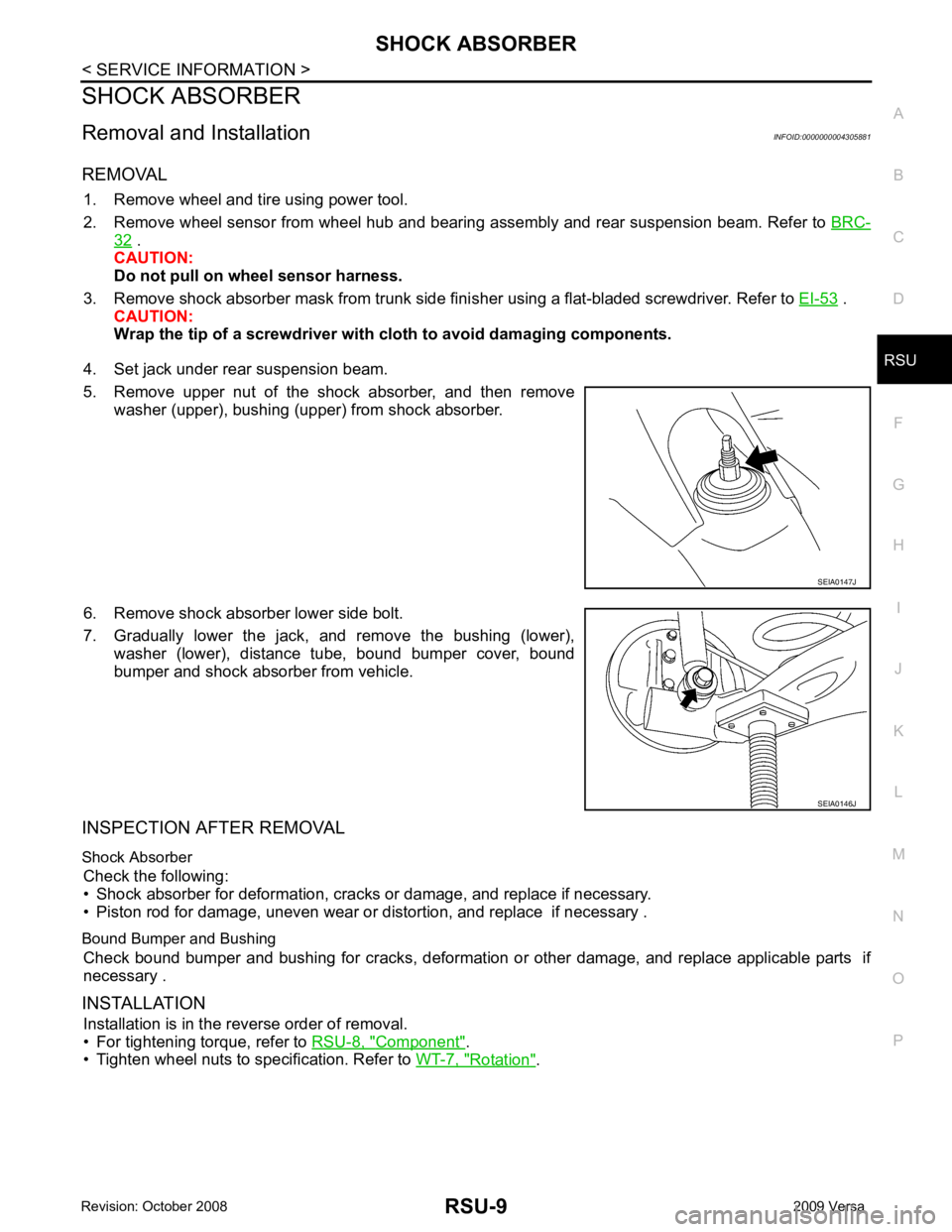
5. Remove upper nut of the shock absorber, and then remove washer (upper), bushing (upper) from shock absorber.
6. Remove shock absorber lower side bolt.
7. Gradually lower the jack, and remove the bushing (lower), washer (lower), distance tube, bound bumper cover, bound
bumper and shock absorber from vehicle.
INSPECTION AFTER REMOVAL
Shock Absorber Check the following:
• Shock absorber for deformation, cracks or damage, and replace if necessary.
• Piston rod for damage, uneven wear or di stortion, and replace if necessary .
Bound Bumper and Bushing Check bound bumper and bushing for cracks, deformation or other damage, and replace applicable parts if
necessary .
INSTALLATION Installation is in the reverse order of removal.
• For tightening torque, refer to RSU-8, " Component " .
• Tighten wheel nuts to specification. Refer to WT-7, " Rotation " .
Page 4278 of 4331
TROUBLE DIAGNOSES
WT-13
< SERVICE INFORMATION >
C
D
F
G H
I
J
K L
M A
B WT
N
O P
6. Inflate all tires to proper pressure. Refer to
WT-27, " Tire " .
Transmitter Wake Up Operation INFOID:0000000004307325
NOTE:
This procedure must be done after replacement of a low tire pressure warning transmitter or BCM.
New replacement transmitters are provided "asleep" and must first be "woken up" using Transmitter
Activation Tool J-45295 before ID registration can be performed.
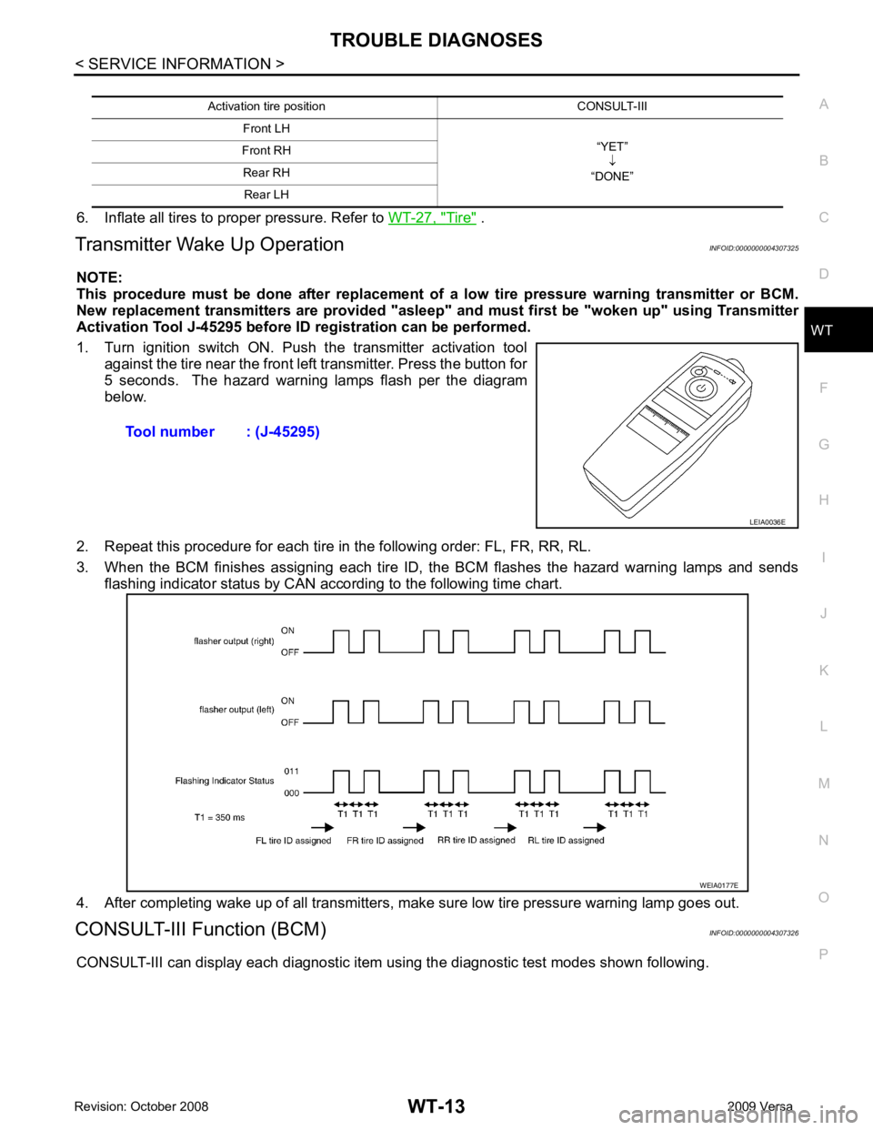
1. Turn ignition switch ON. Push the transmitter activation tool against the tire near the front left transmitter. Press the button for
5 seconds. The hazard warning lamps flash per the diagram
below.
2. Repeat this procedure for each tire in the following order: FL, FR, RR, RL.
3. When the BCM finishes assigning each tire ID, the BCM flashes the hazard warning lamps and sends flashing indicator status by CAN according to the following time chart.
4. After completing wake up of all transmitters, make sure low tire pressure warning lamp goes out.
CONSULT-III Function (BCM) INFOID:0000000004307326
CONSULT-III can display each diagnostic item using the diagnostic test modes shown following. Activation tire position CONSULT-III
Front LH “YET”↓
“DONE”
Front RH
Rear RH Rear LH Tool number : (J-45295)
LEIA0036E
WEIA0177E
Page 4281 of 4331

OK >> GO TO 4.
NG >> Repair or replace damaged parts. OK >> Carry out self-diagnosis.
NG >> Replace battery in transmitter activation tool.
Self-Diagnosis (With CONSULT-III) INFOID:0000000004307329
DESCRIPTION
During driving, the tire pressure monitoring system receives the signal transmitted from the transmitter
installed in each wheel, and turns on the low tire pressure warning lamp when the tire pressure becomes low.
The control unit (BCM) for this system has pressure judgement and self-diagnosis functions.
FUNCTION
When the tire pressure monitoring syst em detects low inflation pressure or an internal malfunction, the low tire
pressure warning lamp in the combination meter comes on. The malfunction location is indicated by the low
tire pressure warning lamp flashing and the buzzer sounding.
CONSULT-III Application to Tire Pressure Monitoring System
× : Applicable
– : Not applicable
Self-Diagnostic Results Mode ITEM SELF-DIAGNOSTIC RESULTS DATA MONITOR
Front - Left transmitter × ×
Front - Right transmitter × ×
Rear - Left transmitter × ×
Rear - Right transmitter × ×
Warning lamp — ×
Vehicle speed × ×
Buzzer (in combination meter) — ×
CAN Communication × × 8, " System Description " .
Page 4290 of 4331
WT
N
O P
REMOVAL AND INSTALLATION
Transmitter (Pressure Sensor) INFOID:0000000004307341
REMOVAL 1. Remove wheel and tire using power tool.
2. Deflate tire. Unscrew transmitter retaining nut and allow transmitter to fall into tire.
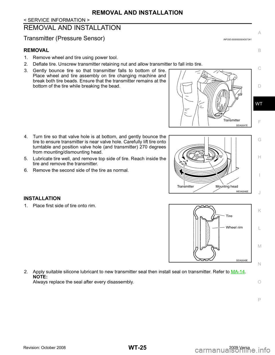
3. Gently bounce tire so that transmitter falls to bottom of tire. Place wheel and tire assembly on tire changing machine and
break both tire beads. Ensure that the transmitter remains at the
bottom of the tire while breaking the bead.
4. Turn tire so that valve hole is at bottom, and gently bounce the tire to ensure transmitter is near valve hole. Carefully lift tire onto
turntable and position valve hole (and transmitter) 270 degrees
from mounting/dismounting head.
5. Lubricate tire well, and remove top side of tire. Reach inside the tire and remove the transmitter.
6. Remove the second side of the tire as normal.
INSTALLATION 1. Place first side of tire onto rim.
2. Apply suitable silicone lubricant to new transmitter seal then install seal on transmitter. Refer to MA-14 .
NOTE:
Always replace the seal after every disassembly.
Page 4291 of 4331
WT-26< SERVICE INFORMATION >
REMOVAL AND INSTALLATION
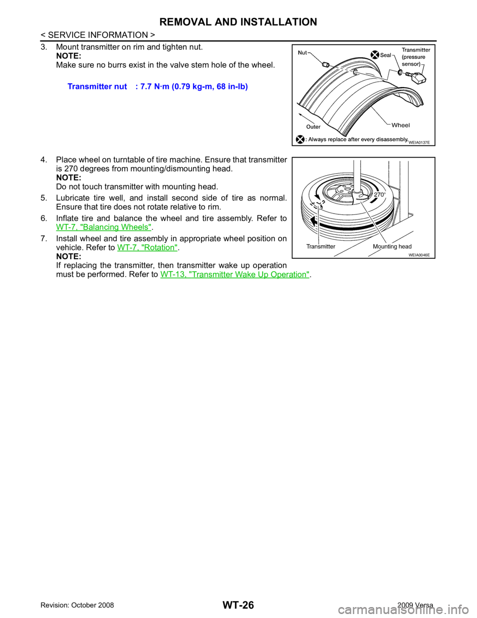
3. Mount transmitter on rim and tighten nut. NOTE:
Make sure no burrs exist in the valve stem hole of the wheel.
4. Place wheel on turntable of tire machine. Ensure that transmitter is 270 degrees from mounting/dismounting head.
NOTE:
Do not touch transmitter with mounting head.
5. Lubricate tire well, and install second side of tire as normal. Ensure that tire does not rotate relative to rim.
6. Inflate tire and balance the wheel and tire assembly. Refer to WT-7, " Balancing Wheels " .
7. Install wheel and tire assembly in appropriate wheel position on vehicle. Refer to WT-7, " Rotation " .
NOTE:
If replacing the transmitter, then transmitter wake up operation
must be performed. Refer to WT-13, " Transmitter Wake Up Operation " .
Transmitter nut : 7.7 N·m (0.79 kg-m, 68 in-lb) WEIA0137E
WEIA0046E