reset NISSAN TIIDA 2009 Service Repair Manual
[x] Cancel search | Manufacturer: NISSAN, Model Year: 2009, Model line: TIIDA, Model: NISSAN TIIDA 2009Pages: 4331, PDF Size: 58.04 MB
Page 419 of 4331
AV
N
O P
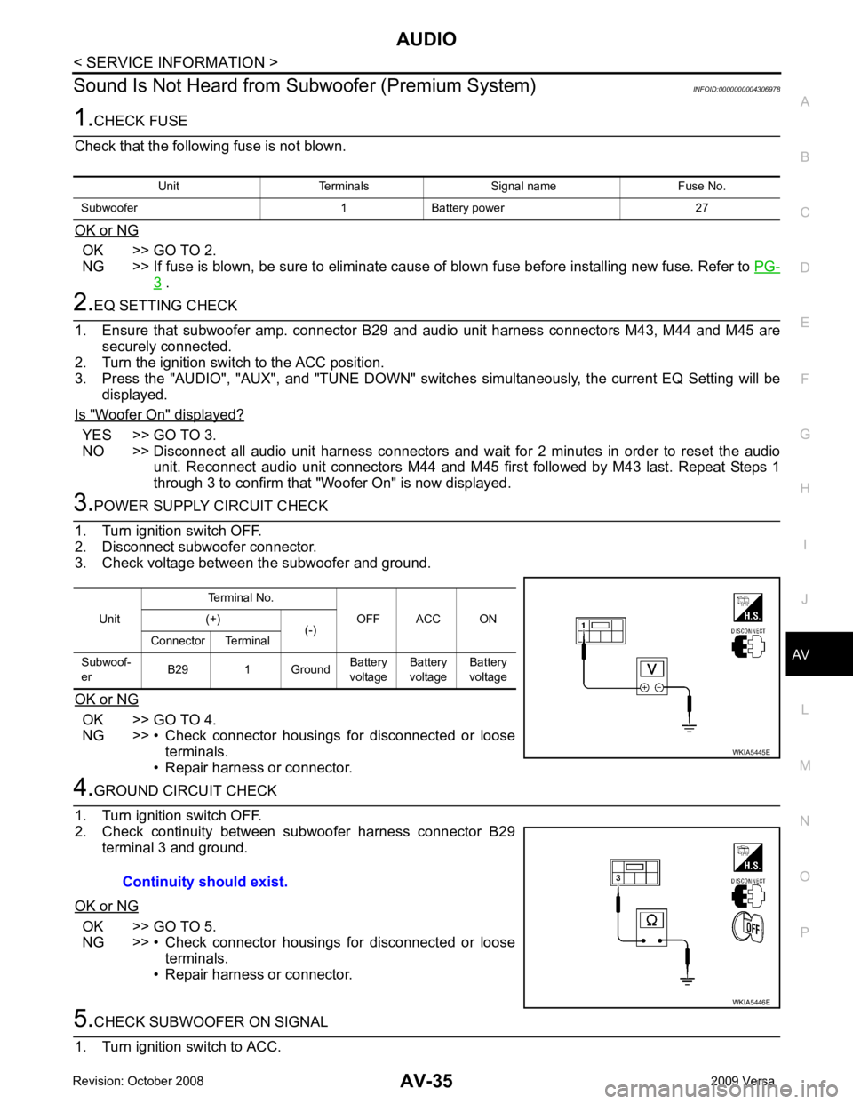
Sound Is Not Heard from Su
bwoofer (Premium System) INFOID:0000000004306978OK >> GO TO 2.
NG >> If fuse is blown, be sure to eliminate cause of blown fuse before installing new fuse. Refer to PG-3 .
YES >> GO TO 3.
NO >> Disconnect all audio unit harness connectors and wait for 2 minutes in order to reset the audio
unit. Reconnect audio unit connectors M44 and M45 first followed by M43 last. Repeat Steps 1
through 3 to confirm that "Woofer On" is now displayed. OK >> GO TO 4.
NG >> • Check connector housings for disconnected or loose terminals.
• Repair harness or connector. OK >> GO TO 5.
NG >> • Check connector housings for disconnected or loose terminals.
• Repair harness or connector. Unit
Terminal No.
OFF ACC ON
(+)
(-)
Connector Terminal
Subwoof-
er B29 1 Ground Battery
voltage Battery
voltage Battery
voltage
Page 459 of 4331

BCS
N
O P
WORK SUPPORT
Display Item List
CAN Communication Inspection Usin g CONSULT-III (Self-Diagnosis) INFOID:0000000004306840Item Description
RESET SETTING VALUE Return a value set with WORK SUPPORT of each system to a default value in factory shipment. CONSULT-III display code Diagnosis item
U1000 INITIAL DIAG
TRANSMIT DIAG ECM
IPDM E/R
METER/M&A I-KEY
Page 1399 of 4331
EC
NP
O
*3: ECM determines the start signal status by the signals of engine speed and battery voltage.
SYSTEM DESCRIPTION The amount of fuel injected from the fuel injector is determined by the ECM. The ECM controls the length of
time the valve remains open (injection pulse duration). T he amount of fuel injected is a program value in the
ECM memory. The program value is preset by engi ne operating conditions. These conditions are determined
by input signals (for engine speed and intake air) from t he crankshaft position sensor (POS), camshaft position
sensor (PHASE) and the mass air flow sensor.
VARIOUS FUEL INJECTION INCREASE/DECREASE COMPENSATION In addition, the amount of fuel injected is compens ated to improve engine performance under various operat-
ing conditions as listed below.
• During warm-up
• When starting the engine
• During acceleration
• Hot-engine operation
• When selector lever is changed from N to D (A/T models)
• High-load, high-speed operation
• During deceleration
• During high engine speed operation
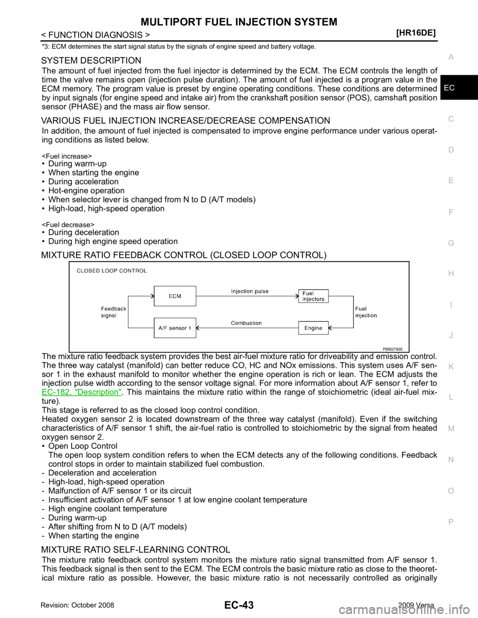
MIXTURE RATIO FEEDBACK CONTROL (CLOSED LOOP CONTROL)
The mixture ratio feedback system prov ides the best air-fuel mixture ratio for driveability and emission control.
The three way catalyst (manifold) can better reduce CO, HC and NOx emissions. This system uses A/F sen-
sor 1 in the exhaust manifold to monitor whether the engine operation is rich or lean. The ECM adjusts the
injection pulse width according to the sensor voltage si gnal. For more information about A/F sensor 1, refer to
EC-182, " Description " . This maintains the mixture ratio within t
he range of stoichiometric (ideal air-fuel mix-
ture).
This stage is referred to as the closed loop control condition.
Heated oxygen sensor 2 is located downstream of the th ree way catalyst (manifold). Even if the switching
characteristics of A/F sensor 1 shift, the air-fuel rati o is controlled to stoichiometric by the signal from heated
oxygen sensor 2.
• Open Loop Control
The open loop system condition refers to when the EC M detects any of the following conditions. Feedback
control stops in order to maintain stabilized fuel combustion.
- Deceleration and acceleration
- High-load, high-speed operation
- Malfunction of A/F sensor 1 or its circuit
- Insufficient activation of A/F sensor 1 at low engine coolant temperature
- High engine coolant temperature
- During warm-up
- After shifting from N to D (A/T models)
- When starting the engine
MIXTURE RATIO SELF-LEARNING CONTROL The mixture ratio feedback control system monitors the mixture ratio signal transmitted from A/F sensor 1.
This feedback signal is then sent to the ECM. The ECM cont rols the basic mixture ratio as close to the theoret-
ical mixture ratio as possible. However, the basic mi xture ratio is not necessarily controlled as originally
Page 1455 of 4331
EC
NP
O
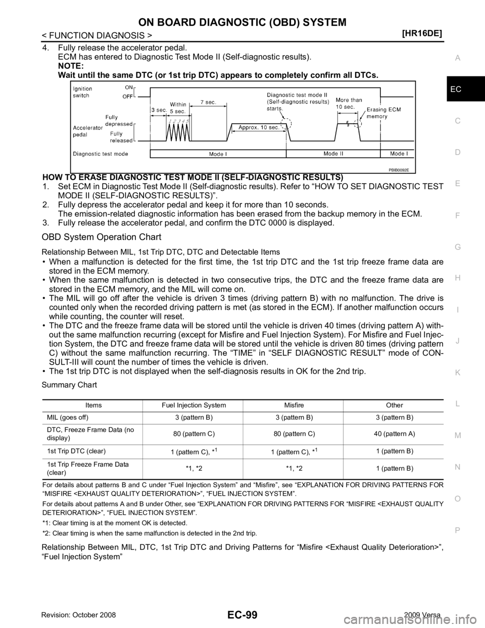
4. Fully release the accelerator pedal.
ECM has entered to Diagnostic Test Mode II (Self-diagnostic results).
NOTE:
Wait until the same DTC (or 1st trip DTC) appears to completely confirm all DTCs.
HOW TO ERASE DIAGNOSTIC TEST MO DE II (SELF-DIAGNOSTIC RESULTS)
1. Set ECM in Diagnostic Test Mode II (Self-diagnostic results). Refer to “HOW TO SET DIAGNOSTIC TEST
MODE II (SELF-DIAGNOSTIC RESULTS)”.
2. Fully depress the accelerator pedal and keep it for more than 10 seconds. The emission-related diagnostic information has been erased from the backup memory in the ECM.
3. Fully release the accelerator pedal, and confirm the DTC 0000 is displayed.
OBD System Operation Chart
Relationship Between MIL, 1st Trip DTC, DTC and Detectable Items
• When a malfunction is detected for the first time, the 1st trip DTC and the 1st trip freeze frame data are
stored in the ECM memory.
• When the same malfunction is detected in two consec utive trips, the DTC and the freeze frame data are
stored in the ECM memory, and the MIL will come on.
• The MIL will go off after the vehicle is driven 3 times (driving pattern B) with no malfunction. The drive is
counted only when the recorded driving pattern is met (as stored in the ECM). If another malfunction occurs
while counting, the counter will reset.
• The DTC and the freeze frame data will be stored until the v ehicle is driven 40 times (driving pattern A) with-
out the same malfunction recurring (except for Misfire and Fuel Injection System). For Misfire and Fuel Injec-
tion System, the DTC and freeze frame data will be stored until the vehicle is driven 80 times (driving pattern
C) without the same malfunction recurring. The “T IME” in “SELF DIAGNOSTIC RESULT” mode of CON-
SULT-III will count the number of times the vehicle is driven.
• The 1st trip DTC is not displayed when the self-diagnosis results in OK for the 2nd trip.
Summary Chart
For details about patterns B an d C under “Fuel Injection System” and “Misfire”, see “EXPLAN ATION FOR DRIVING PATTERNS FOR
“MISFIRE
For details about patterns A and B under Other, see “EXPLANATION FOR DRIVING PATTERNS FOR “MISFIRE
*1: Clear timing is at the moment OK is detected.
*2: Clear timing is when the same malfunction is detected in the 2nd trip.
Relationship Between MIL, DTC, 1st Tr ip DTC and Driving Patterns for “Misfire
“Fuel Injection System”
Page 1466 of 4331
P0455
EC-329 EVP V/S LEAK P0456/P1456* P0456
EC-335A/F SEN1
A/F SEN1 (B1) P1278/P1279 P0133
EC-198A/F SEN1 (B1) P1276 P0130
EC-182HO2S2
HO2S2 (B1) P1146 P0138
EC-212HO2S2 (B1) P1147 P0137
EC-204HO2S2 (B1) P139 P0139
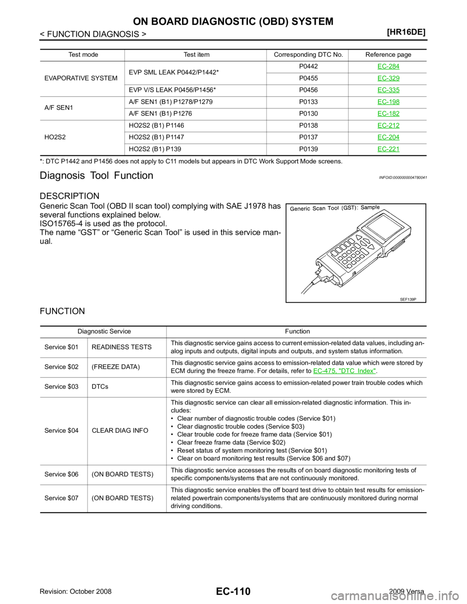
EC-221 DTC Index " .
Service $03 DTCs This diagnostic service gains access to emission-related power train trouble codes which
were stored by ECM.
Service $04 CLEAR DIAG INFO This diagnostic service can clear all emission-related diagnostic information. This in-
cludes:
• Clear number of diagnostic trouble codes (Service $01)
• Clear diagnostic trouble codes (Service $03)
• Clear trouble code for freeze frame data (Service $01)
• Clear freeze frame data (Service $02)
• Reset status of system monitoring test (Service $01)
• Clear on board monitoring test results (Service $06 and $07)
Service $06 (ON BOARD TESTS) This diagnostic service accesses the results of on board diagnostic monitoring tests of
specific components/systems that are not continuously monitored.
Service $07 (ON BOARD TESTS) This diagnostic service enables the off board test drive to obtain test results for emission-
related powertrain components/systems that are continuously monitored during normal
driving conditions.
Page 1875 of 4331
EC
NP
O
*1: This sensor is not used to control the engine system under normal conditions.
*2: This signal is sent to the ECM through CAN communication line.
*3: ECM determines the start signal status by the signals of engine speed and battery voltage.
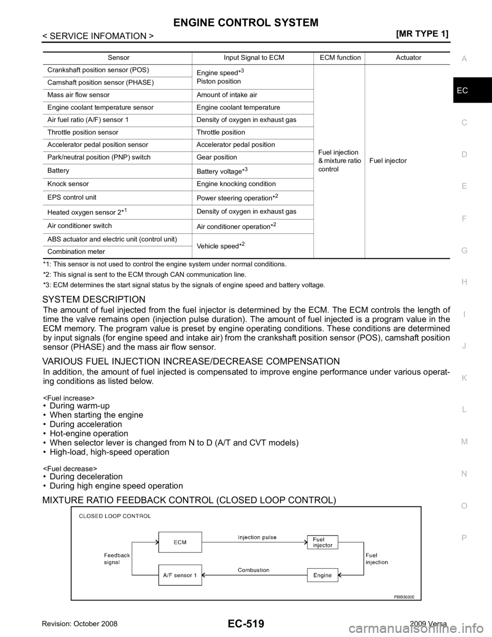
SYSTEM DESCRIPTION The amount of fuel injected from the fuel injector is determined by the ECM. The ECM controls the length of
time the valve remains open (injection pulse duration). T he amount of fuel injected is a program value in the
ECM memory. The program value is preset by engi ne operating conditions. These conditions are determined
by input signals (for engine speed and intake air) from t he crankshaft position sensor (POS), camshaft position
sensor (PHASE) and the mass air flow sensor.
VARIOUS FUEL INJECTION INCREASE/DECREASE COMPENSATION In addition, the amount of fuel injected is compens ated to improve engine performance under various operat-
ing conditions as listed below.
• During warm-up
• When starting the engine
• During acceleration
• Hot-engine operation
• When selector lever is changed from N to D (A/T and CVT models)
• High-load, high-speed operation
• During deceleration
• During high engine speed operation
MIXTURE RATIO FEEDBACK CONTROL (CLOSED LOOP CONTROL) Sensor Input Signal to ECM ECM function Actuator
Crankshaft position sensor (POS) Engine speed*3
Piston position
Fuel injection
& mixture ratio
control Fuel injector
Camshaft position sensor (PHASE)
Mass air flow sensor Amount of intake air
Engine coolant temperature sensor Engine coolant temperature
Air fuel ratio (A/F) sensor 1 Density of oxygen in exhaust gas
Throttle position sensor Throttle position
Accelerator pedal position sensor Accelerator pedal position
Park/neutral position (PNP) switch Gear position
Battery Battery voltage*3
Knock sensor Engine knocking condition
EPS control unit Power steering operation*2
Heated oxygen sensor 2* 1
Density of oxygen in exhaust gas
Air conditioner switch Air conditioner operation*2
ABS actuator and electric unit (control unit) Vehicle speed*2
Combination meter
Page 1916 of 4331
)
How to Erase Diagnostic Test Mode II (Self-diagnostic Results)
The DTC can be erased from the back-up memory in the ECM by depressing accelerator pedal.
Refer to "How to Erase Diagnostic Test Mode II (Self-diagnostic Results)".
• If the battery is disconnected, the DTC will be lost from the backup memory within 24 hours.
• Be careful not to erase the stored memo ry before starting trouble diagnoses.
OBD System Operation Chart INFOID:0000000004537042
RELATIONSHIP BETWEEN MIL, 1ST TRIP DTC, DTC, AND DETECTABLE ITEMS
• When a malfunction is detected for the first time, the 1st trip DTC and the 1st trip freeze frame data are
stored in the ECM memory.
• When the same malfunction is detected in two consec utive trips, the DTC and the freeze frame data are
stored in the ECM memory, and the MIL will come on. For details, refer to EC-541, " Two Trip Detection
Logic " .
• The MIL will go off after the vehicle is driven 3 time s (driving pattern B) with no malfunction. The drive is
counted only when the recorded driving pattern is met (as stored in the ECM). If another malfunction occurs
while counting, the counter will reset.
• The DTC and the freeze frame data will be stored until the vehicle is driven 40 times (driving pattern A) with-
out the same malfunction recurring (except for Misfire and Fuel Injection System). For Misfire and Fuel Injec-
tion System, the DTC and freez e frame data will be stored until the vehicle is driven 80 times (driving pattern
Page 1969 of 4331
![NISSAN TIIDA 2009 Service Repair Manual TROUBLE DIAGNOSIS
EC-613
< SERVICE INFOMATION >
[MR TYPE 1] C
D E
F
G H
I
J
K L
M A EC
NP
O
INSPECTION PROCEDURE
1. Turn ignition switch OFF.
2. Connect GST to data link connector (1), which i NISSAN TIIDA 2009 Service Repair Manual TROUBLE DIAGNOSIS
EC-613
< SERVICE INFOMATION >
[MR TYPE 1] C
D E
F
G H
I
J
K L
M A EC
NP
O
INSPECTION PROCEDURE
1. Turn ignition switch OFF.
2. Connect GST to data link connector (1), which i](/img/5/57398/w960_57398-1968.png)
TROUBLE DIAGNOSIS
EC-613
< SERVICE INFOMATION >
[MR TYPE 1] C
D E
F
G H
I
J
K L
M A EC
NP
O
INSPECTION PROCEDURE
1. Turn ignition switch OFF.
2. Connect GST to data link connector (1), which is located under LH dash panel.
3. Turn ignition switch ON.
4. Enter the program according to instruction on the screen or in the operation manual.
(*: Regarding GST screens in this section, sample screens are
shown.) Diagnostic test mode Function
Service $01 READINESS TESTS This diagnostic service gains access to current emission-related data values, including an-
alog inputs and outputs, digital inputs and outputs, and system status information.
Service $02 (FREEZE DATA) This diagnostic service gains access to emission-related data value which were stored by
ECM during the freeze frame. For details, refer to EC-604, " CONSULT-III Function (EN-
GINE) " .
Service $03 DTCs This diagnostic service gains access to emission-related power train trouble codes which
were stored by ECM.
Service $04 CLEAR DIAG INFO This diagnostic service can clear all emission-related diagnostic information. This in-
cludes:
• Clear number of diagnostic trouble codes (Service $01)
• Clear diagnostic trouble codes (Service $03)
• Clear trouble code for freeze frame data (Service $01)
• Clear freeze frame data (Service $02)
• Reset status of system monitoring test (Service $01)
• Clear on board monitoring test results (Service $06 and $07)
Service $06 (ON BOARD TESTS) This diagnostic service accesses the results of on board diagnostic monitoring tests of
specific components/systems that are not continuously monitored.
Service $07 (ON BOARD TESTS) This diagnostic service enables the off board test drive to obtain test results for emission-
related powertrain components/systems that are continuously monitored during normal
driving conditions.
Service $08 — This diagnostic service can close EVAP system in ignition switch ON position (Engine
stopped). When this diagnostic service is performed, EVAP canister vent control valve can
be closed. In the following conditions, this diagnostic service cannot function.
• Low ambient temperature
• Low battery voltage
• Engine running
• Ignition switch OFF
• Low fuel temperature
• Too much pressure is applied to EVAP system
Service $09 (CALIBRATION ID) This diagnostic service enables the off-board test device to request specific vehicle infor-
mation such as Vehicle Identification Number (VIN) and Calibration IDs. BBIA0734E
SEF398S
Page 2384 of 4331
![NISSAN TIIDA 2009 Service Repair Manual EC-1028< SERVICE INFOMATION >
[MR TYPE 2]
ENGINE CONTROL SYSTEM
*1: This sensor is not used to control the engine system under normal conditions.
*2: This signal is sent to the ECM through CAN communi NISSAN TIIDA 2009 Service Repair Manual EC-1028< SERVICE INFOMATION >
[MR TYPE 2]
ENGINE CONTROL SYSTEM
*1: This sensor is not used to control the engine system under normal conditions.
*2: This signal is sent to the ECM through CAN communi](/img/5/57398/w960_57398-2383.png)
EC-1028< SERVICE INFOMATION >
[MR TYPE 2]
ENGINE CONTROL SYSTEM
*1: This sensor is not used to control the engine system under normal conditions.
*2: This signal is sent to the ECM through CAN communication line.
*3: ECM determines the start signal status by the signals of engine speed and battery voltage.
SYSTEM DESCRIPTION
The amount of fuel injected from the fuel injector is determined by the ECM. The ECM controls the length of
time the valve remains open (injection pulse duration). T he amount of fuel injected is a program value in the
ECM memory. The program value is preset by engi ne operating conditions. These conditions are determined
by input signals (for engine speed and intake air) from t he crankshaft position sensor (POS), camshaft position
sensor (PHASE) and the ma ss air flow sensor.
VARIOUS FUEL INJECTION I NCREASE/DECREASE COMPENSATION
In addition, the amount of fuel injected is compens ated to improve engine performance under various operat-
ing conditions as listed below.
• During warm-up
• When starting the engine
• During acceleration
• Hot-engine operation
• When selector lever is changed from N to D (A/T and CVT models)
• High-load, high-speed operation
• During deceleration
• During high engine speed operation
MIXTURE RATIO FEEDBACK CONTROL (CLOSED LOOP CONTROL) Sensor Input Signal to ECM ECM function Actuator
Crankshaft position sensor (POS) Engine speed*3
Piston position
Fuel injection
& mixture ratio
control Fuel injector
Camshaft position sensor (PHASE)
Mass air flow sensor Amount of intake air
Engine coolant temperature sensor Engine coolant temperature
Air fuel ratio (A/F) sensor 1 Density of oxygen in exhaust gas
Throttle position sensor Throttle position
Accelerator pedal position sensor Accelerator pedal position
Park/neutral position (PNP) switch Gear position
Battery Battery voltage*3
Knock sensor Engine knocking condition
EPS control unit Power steering operation*2
Heated oxygen sensor 2* 1
Density of oxygen in exhaust gas
Air conditioner switch Air conditioner operation*2
ABS actuator and electric unit (control unit)
Vehicle speed*2
Combination meter PBIB3020E
Page 2428 of 4331
![NISSAN TIIDA 2009 Service Repair Manual EC-1072< SERVICE INFOMATION >
[MR TYPE 2]
ON BOARD DIAGNOSTIC (OBD) SYSTEM
tified codes can be identified by using the CONSULT-II I or GST. A DTC will be used as an example for how to
read a code.
A p NISSAN TIIDA 2009 Service Repair Manual EC-1072< SERVICE INFOMATION >
[MR TYPE 2]
ON BOARD DIAGNOSTIC (OBD) SYSTEM
tified codes can be identified by using the CONSULT-II I or GST. A DTC will be used as an example for how to
read a code.
A p](/img/5/57398/w960_57398-2427.png)
EC-1072< SERVICE INFOMATION >
[MR TYPE 2]
ON BOARD DIAGNOSTIC (OBD) SYSTEM
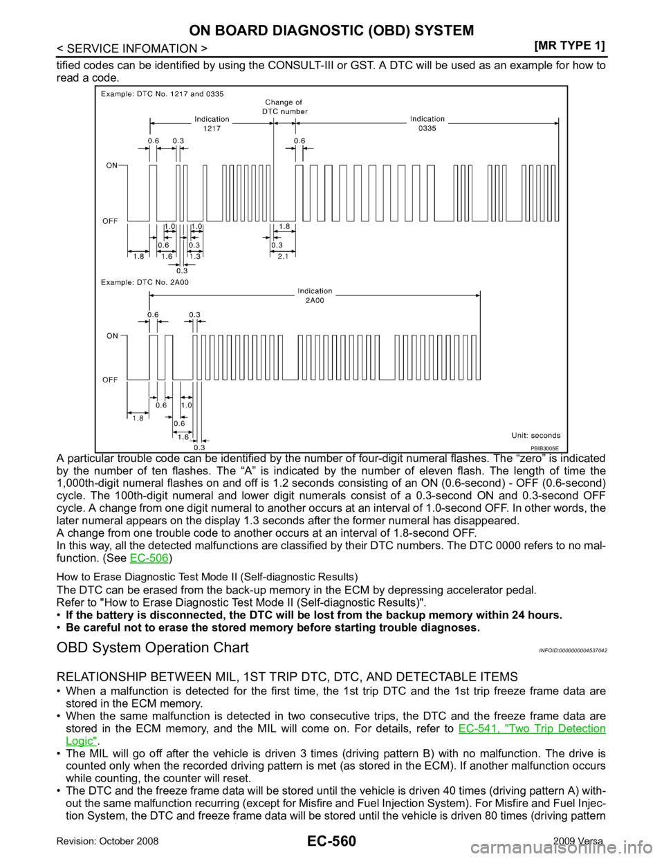
tified codes can be identified by using the CONSULT-II I or GST. A DTC will be used as an example for how to
read a code.
A particular trouble code can be identified by the number of four-digit numeral flashes. The “zero” is indicated
by the number of ten flashes. The “A” is indicated by the number of eleven flash. The length of time the
1,000th-digit numeral flashes on and off is 1.2 seconds consisting of an ON (0.6-second) - OFF (0.6-second)
cycle. The 100th-digit numeral and lower digit numer als consist of a 0.3-second ON and 0.3-second OFF
cycle. A change from one digit numeral to another occurs at an interval of 1.0-second OFF. In other words, the
later numeral appears on the display 1.3 seconds after the former numeral has disappeared.
A change from one trouble code to another occu rs at an interval of 1.8-second OFF.
In this way, all the detected malfunctions are classi fied by their DTC numbers. The DTC 0000 refers to no mal-
function. (See EC-1015 )
How to Erase Diagnostic Test Mode II (Self-diagnostic Results)
The DTC can be erased from the back-up memory in the ECM by depressing accelerator pedal.
Refer to "How to Erase Diagnostic Test Mode II (Self-diagnostic Results)".
• If the battery is disconnected, the DTC will be lost from the backup memory within 24 hours.
• Be careful not to erase the stored memo ry before starting trouble diagnoses.
OBD System Operation Chart INFOID:0000000004499928
RELATIONSHIP BETWEEN MIL, 1ST TRIP DTC, DTC, AND DETECTABLE ITEMS
• When a malfunction is detected for the first time, the 1st trip DTC and the 1st trip freeze frame data are
stored in the ECM memory.
• When the same malfunction is detected in two consec utive trips, the DTC and the freeze frame data are
stored in the ECM memory, and the MIL will come on. For details, refer to EC-1051, " Two Trip Detection
Logic " .
• The MIL will go off after the vehicle is driven 3 time s (driving pattern B) with no malfunction. The drive is
counted only when the recorded driving pattern is met (as stored in the ECM). If another malfunction occurs
while counting, the counter will reset.
• The DTC and the freeze frame data will be stored until the vehicle is driven 40 times (driving pattern A) with-
out the same malfunction recurring (except for Misfire and Fuel Injection System). For Misfire and Fuel Injec-
tion System, the DTC and freez e frame data will be stored until the vehicle is driven 80 times (driving pattern PBIB3005E