set clock NISSAN TIIDA 2009 Service Repair Manual
[x] Cancel search | Manufacturer: NISSAN, Model Year: 2009, Model line: TIIDA, Model: NISSAN TIIDA 2009Pages: 4331, PDF Size: 58.04 MB
Page 362 of 4331
ASSEMBLY
AT-357
< SERVICE INFORMATION >
D
E
F
G H
I
J
K L
M A
B AT
N
O P
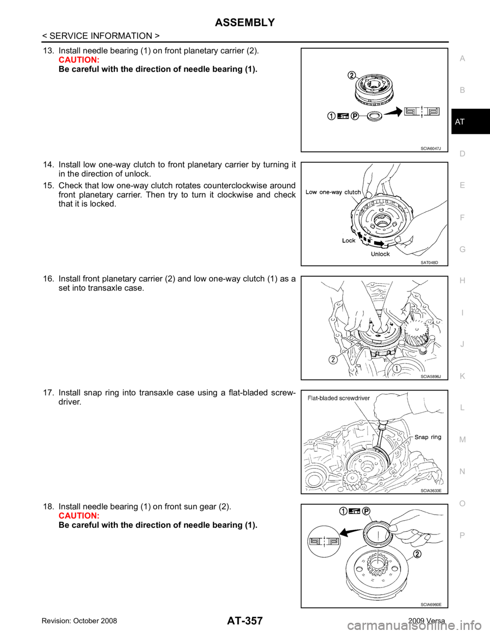
13. Install needle bearing (1) on front planetary carrier (2).
CAUTION:
Be careful with the direct ion of needle bearing (1).
14. Install low one-way clutch to front planetary carrier by turning it in the direction of unlock.
15. Check that low one-way clutch rotates counterclockwise around front planetary carrier. Then try to turn it clockwise and check
that it is locked.
16. Install front planetary carrier (2) and low one-way clutch (1) as a set into transaxle case.
17. Install snap ring into transaxle case using a flat-bladed screw- driver.
18. Install needle bearing (1) on front sun gear (2). CAUTION:
Be careful with the direct ion of needle bearing (1). SCIA6047J
SAT048D
SCIA5896J
SCIA3633E
SCIA6960E
Page 807 of 4331
BR
N
O P
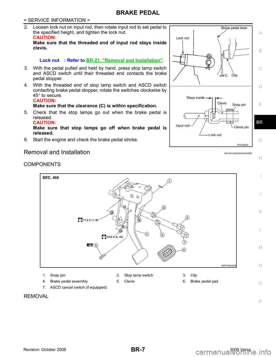
2. Loosen lock nut on input rod, then rotate input rod to set pedal to
the specified height, and tighten the lock nut.
CAUTION:
Make sure that the threaded end of input rod stays inside
clevis.
3. With the pedal pulled and held by hand, press stop lamp switch and ASCD switch until their threaded end contacts the brake
pedal stopper.
4. With the threaded end of stop lamp switch and ASCD switch contacting brake pedal stopper, rotate the switches clockwise by
45 ° to secure.
CAUTION:
Make sure that the clearance (C) is within specification.
5. Check that the stop lamps go out when the brake pedal is released.
CAUTION:
Make sure that stop lamps go off when brake pedal is
released.
6. Start the engine and check the brake pedal stroke.
Removal and Installation INFOID:0000000004305891
COMPONENTS
REMOVAL Lock nut : Refer to
BR-21, " Removal and Installation " .
Page 1454 of 4331
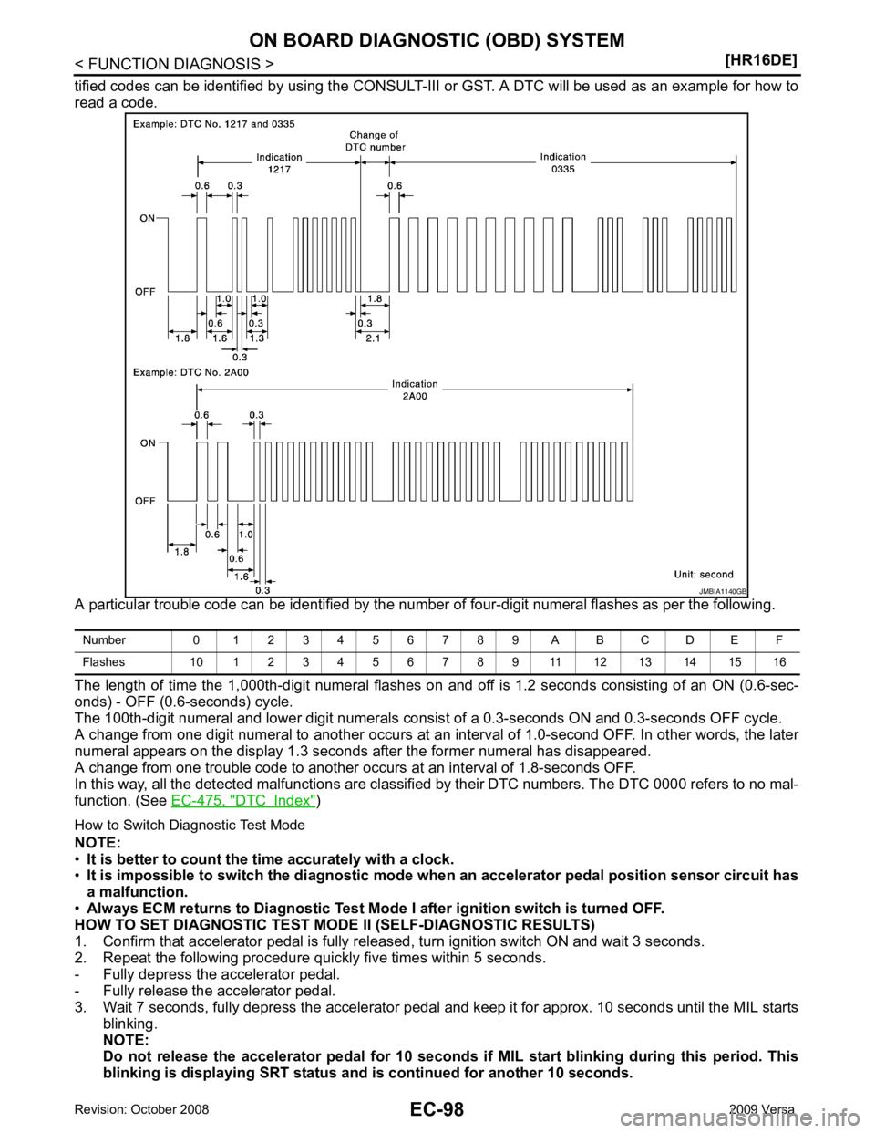
DTC Index " )
How to Switch Diagnostic Test Mode
NOTE:
• It is better to count the ti me accurately with a clock.
• It is impossible to switch the di agnostic mode when an accelerator pedal position sensor circuit has
a malfunction.
• Always ECM returns to Diagnostic Test Mode I after ignition switch is turned OFF.
HOW TO SET DIAGNOSTIC TEST MODE II (SELF-DIAGNOSTIC RESULTS)
1. Confirm that accelerator pedal is fully releas ed, turn ignition switch ON and wait 3 seconds.
2. Repeat the following procedure quickly five times within 5 seconds.
- Fully depress the accelerator pedal.
- Fully release the accelerator pedal.
3. Wait 7 seconds, fully depress the accelerator pedal and keep it for approx. 10 seconds until the MIL starts
blinking.
NOTE:
Do not release the accelerator pedal for 10 seconds if MIL start blinking during this period. This
blinking is displaying SRT status and is continued for another 10 seconds.
Page 1914 of 4331
Emission-
related Diagnostic Information " .
HOW TO SWITCH DIAGNOSTIC TEST MODE
NOTE:
• It is better to count the ti me accurately with a clock.
• It is impossible to switch the di agnostic mode when an accelerator pedal position sensor circuit has
a malfunction.
• Always ECM returns to Diagnostic Test Mode I after ignition switch is turned OFF.
How to Set Diagnostic Test Mode II (Self-diagnostic Results)
1. Confirm that accelerator pedal is fully releas ed, turn ignition switch ON and wait 3 seconds.
2. Repeat the following procedure quickly five times within 5 seconds.
a. Fully depress the accelerator pedal.
b. Fully release the accelerator pedal.
3. Wait 7 seconds, fully depress the accelerator pedal and keep it for approx. 10 seconds until the MIL starts blinking.
4. Fully release the accelerator pedal. Diagnostic Test
Mode KEY and ENG.
Status Function Explanation of Function
Mode I Ignition switch in ON position
Engine stopped BULB CHECK This function checks the MIL bulb for damage (blown, open
circuit, etc.).
If the MIL does not come on, check MIL circuit.
Engine running MALFUNCTION WARNING This is a usual driving condition. When a malfunction is de-
tected twice in two consecutive driving cycles (two trip de-
tection logic), the MIL will light up to inform the driver that a
malfunction has been detected.
The following malfunctions will light up or blink the MIL in
the 1st trip.
• Misfire (Possible three way catalyst damage)
• One trip detection diagnoses
Mode II Ignition switch in ON position
Engine stopped SELF-DIAGNOSTIC
RESULTS This function allows DTCs an
d 1st trip DTCs to be read.
Page 2211 of 4331
![NISSAN TIIDA 2009 Service Repair Manual DTC P0456 EVAP CONTROL SYSTEM
EC-855
< SERVICE INFOMATION >
[MR TYPE 1] C
D E
F
G H
I
J
K L
M A EC
NP
O
2. Set the pressure pump and a hose.
3. Also set the pressure pump with pressure gauge t NISSAN TIIDA 2009 Service Repair Manual DTC P0456 EVAP CONTROL SYSTEM
EC-855
< SERVICE INFOMATION >
[MR TYPE 1] C
D E
F
G H
I
J
K L
M A EC
NP
O
2. Set the pressure pump and a hose.
3. Also set the pressure pump with pressure gauge t](/img/5/57398/w960_57398-2210.png)
DTC P0456 EVAP CONTROL SYSTEM
EC-855
< SERVICE INFOMATION >
[MR TYPE 1] C
D E
F
G H
I
J
K L
M A EC
NP
O
2. Set the pressure pump and a hose.
3. Also set the pressure pump with pressure gauge to the EVAP service port adapter.
4. Turn ignition switch ON.
5. Connect GST and select Service $08.
6. Using Service $08 control the EVAP canister vent control valve
(close).
7. Apply pressure and make sure the following conditions are sat- isfied.
Pressure to be applied: 2.7 kPa (20 mmHg, 0.79 inHg)
Time to be waited after the pressure drawn in to the EVAP
system and the pressure to be dropped: 60 seconds and
the pressure should not be dropped more than 0.4 kPa (3 mmHg, 0.12 inHg).
If NG, go to EC-855, " Diagnosis Procedure " .
If OK, go to next step.
8. Disconnect GST.
9. Start engine and warm it up to normal operating temperature.
10. Turn ignition switch OFF and wait at least 10 seconds.
11. Restart engine and let it idle for 90 seconds.
12. Keep engine speed at 2,000 rpm for 30 seconds.
13. Turn ignition switch OFF. NOTE:
For more information, refe r to GST Instruction Manual.
Diagnosis Procedure INFOID:00000000045373481.
CHECK FUEL FILLER CAP DESIGN
1. Turn ignition switch OFF.
2. Check for genuine NISSAN fuel filler cap design.
OK or NG OK >> GO TO 2.
NG >> Replace with genuine NISSAN fuel filler cap. 2.
CHECK FUEL FILLER CAP INSTALLATION
Check that the cap is tightened properly by rotating the cap clockwise.
OK or NG OK >> GO TO 3.
NG >> 1. Open fuel filler cap, then clean cap and fuel filler neck threads using air blower. 2. Retighten until reteaching sound is heard. 3.
CHECK FUEL FILLER CAP FUNCTION
Check for air releasing sound while opening the fuel filler cap.
OK or NG OK >> GO TO 5.
NG >> GO TO 4. 4.
CHECK FUEL TANK VACUUM RELIEF VALVE
Refer to EC-529, " Component Inspection " .
OK or NG OK >> GO TO 5.
NG >> Replace fuel filler cap with a genuine one. SEF462UI
SEF915U
Page 2426 of 4331
Emission-
related Diagnostic Information " .
HOW TO SWITCH DIAGNOSTIC TEST MODE
NOTE:
• It is better to count the ti me accurately with a clock.
• It is impossible to switch the di agnostic mode when an accelerator pedal position sensor circuit has
a malfunction.
• Always ECM returns to Diagnostic Test Mode I after ignition switch is turned OFF.
How to Set Diagnostic Test Mode II (Self-diagnostic Results)
1. Confirm that accelerator pedal is fully releas ed, turn ignition switch ON and wait 3 seconds.
2. Repeat the following procedure quickly five times within 5 seconds.
a. Fully depress the accelerator pedal.
b. Fully release the accelerator pedal.
3. Wait 7 seconds, fully depress the accelerator pedal and keep it for approx. 10 seconds until the MIL starts blinking.
4. Fully release the accelerator pedal. Diagnostic Test
Mode KEY and ENG.
Status Function Explanation of Function
Mode I Ignition switch in ON position
Engine stopped BULB CHECK This function checks the MIL bulb for damage (blown, open
circuit, etc.).
If the MIL does not come on, check MIL circuit.
Engine running MALFUNCTION WARNING This is a usual driving condition. When a malfunction is de-
tected twice in two consecutive driving cycles (two trip de-
tection logic), the MIL will light up to inform the driver that a
malfunction has been detected.
The following malfunctions will light up or blink the MIL in
the 1st trip.
• Misfire (Possible three way catalyst damage)
• One trip detection diagnoses
Mode II Ignition switch in ON position
Engine stopped SELF-DIAGNOSTIC
RESULTS This function allows DTCs an
d 1st trip DTCs to be read.
Page 2731 of 4331
![NISSAN TIIDA 2009 Service Repair Manual DTC P0456 EVAP CONTROL SYSTEM
EC-1375
< SERVICE INFOMATION >
[MR TYPE 2] C
D E
F
G H
I
J
K L
M A EC
NP
O
2. Set the pressure pump and a hose.
3. Also set the pressure pump with pressure gauge NISSAN TIIDA 2009 Service Repair Manual DTC P0456 EVAP CONTROL SYSTEM
EC-1375
< SERVICE INFOMATION >
[MR TYPE 2] C
D E
F
G H
I
J
K L
M A EC
NP
O
2. Set the pressure pump and a hose.
3. Also set the pressure pump with pressure gauge](/img/5/57398/w960_57398-2730.png)
DTC P0456 EVAP CONTROL SYSTEM
EC-1375
< SERVICE INFOMATION >
[MR TYPE 2] C
D E
F
G H
I
J
K L
M A EC
NP
O
2. Set the pressure pump and a hose.
3. Also set the pressure pump with pressure gauge to the EVAP service port adapter.
4. Turn ignition switch ON.
5. Connect GST and select Service $08.
6. Using Service $08 control the EVAP canister vent control valve
(close).
7. Apply pressure and make sure the following conditions are sat- isfied.
Pressure to be applied: 2.7 kPa (20 mmHg, 0.79 inHg)
Time to be waited after the pressure drawn in to the EVAP
system and the pressure to be dropped: 60 seconds and
the pressure should not be dropped more than 0.4 kPa (3 mmHg, 0.12 inHg).
If NG, go to EC-1375, " Diagnosis Procedure " .
If OK, go to next step.
8. Disconnect GST.
9. Start engine and warm it up to normal operating temperature.
10. Turn ignition switch OFF and wait at least 10 seconds.
11. Restart engine and let it idle for 90 seconds.
12. Keep engine speed at 2,000 rpm for 30 seconds.
13. Turn ignition switch OFF. NOTE:
For more information, refe r to GST Instruction Manual.
Diagnosis Procedure INFOID:00000000045002341.
CHECK FUEL FILLER CAP DESIGN
1. Turn ignition switch OFF.
2. Check for genuine NISSAN fuel filler cap design.
OK or NG OK >> GO TO 2.
NG >> Replace with genuine NISSAN fuel filler cap. 2.
CHECK FUEL FILLER CAP INSTALLATION
Check that the cap is tightened properly by rotating the cap clockwise.
OK or NG OK >> GO TO 3.
NG >> 1. Open fuel filler cap, then clean cap and fuel filler neck threads using air blower. 2. Retighten until reteaching sound is heard. 3.
CHECK FUEL FILLER CAP FUNCTION
Check for air releasing sound while opening the fuel filler cap.
OK or NG OK >> GO TO 5.
NG >> GO TO 4. 4.
CHECK FUEL TANK VACUUM RELIEF VALVE
Refer to EC-1038, " Component Inspection " .
OK or NG OK >> GO TO 5.
NG >> Replace fuel filler cap with a genuine one. SEF462UI
SEF915U
Page 2967 of 4331
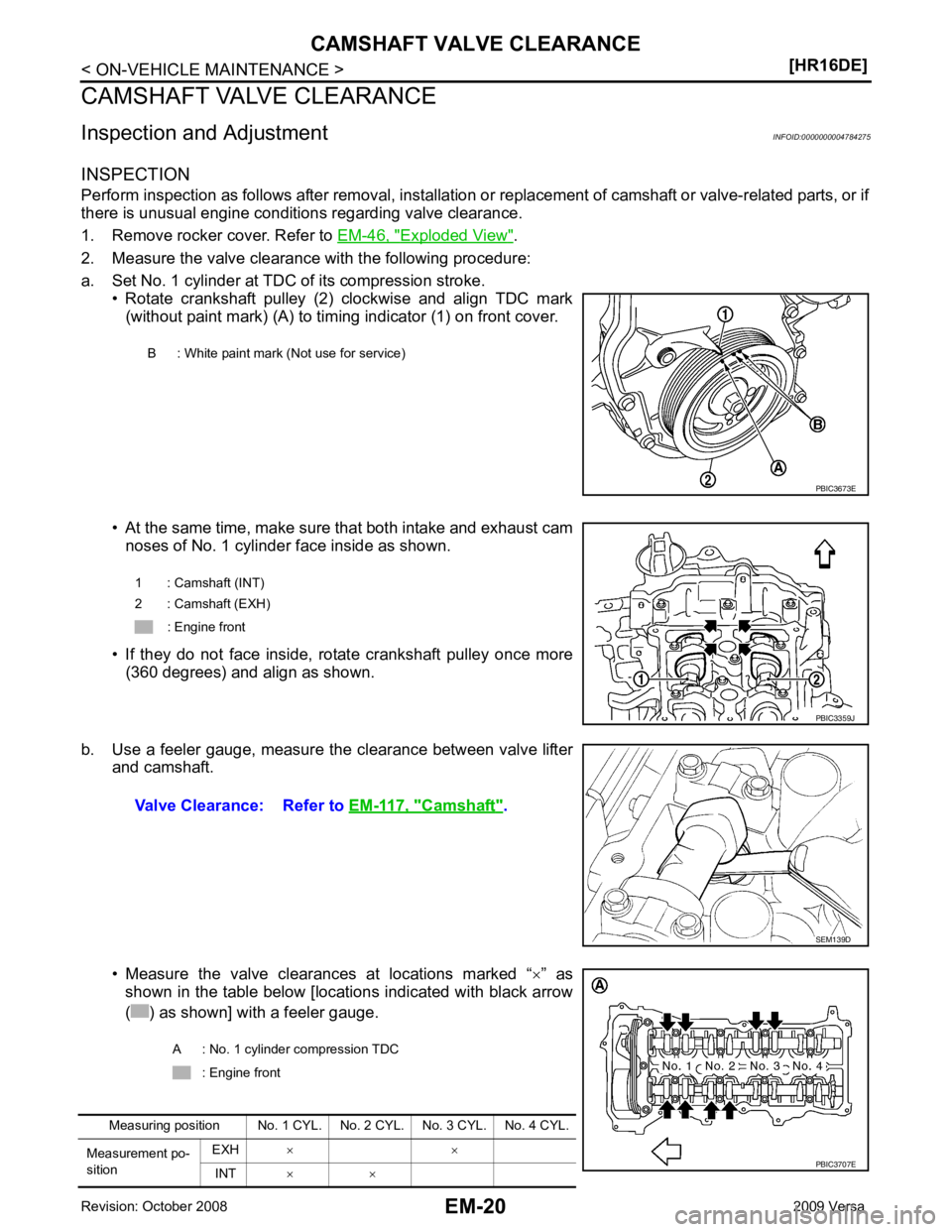
Exploded View " .
2. Measure the valve clearance with the following procedure:
a. Set No. 1 cylinder at TDC of its compression stroke. • Rotate crankshaft pulley (2) clockwise and align TDC mark(without paint mark) (A) to timing indicator (1) on front cover.
• At the same time, make sure that both intake and exhaust cam noses of No. 1 cylinder face inside as shown.
• If they do not face inside, rotate crankshaft pulley once more (360 degrees) and align as shown.
b. Use a feeler gauge, measure the clearance between valve lifter and camshaft.
• Measure the valve clearances at locations marked “ ×” as
shown in the table below [locations indicated with black arrow
( ) as shown] with a feeler gauge. B : White paint mark (Not use for service)
Camshaft " .
Page 2997 of 4331
![NISSAN TIIDA 2009 Service Repair Manual EM-50< ON-VEHICLE REPAIR >
[HR16DE]
TIMING CHAIN
4. Remove the following parts. • Intake manifold: Refer to EM-28, " Exploded View " .
• Drive belt: Refer to EM-15, " Removal and Installation " NISSAN TIIDA 2009 Service Repair Manual EM-50< ON-VEHICLE REPAIR >
[HR16DE]
TIMING CHAIN
4. Remove the following parts. • Intake manifold: Refer to EM-28, " Exploded View " .
• Drive belt: Refer to EM-15, " Removal and Installation "](/img/5/57398/w960_57398-2996.png)
EM-50< ON-VEHICLE REPAIR >
[HR16DE]
TIMING CHAIN
4. Remove the following parts. • Intake manifold: Refer to EM-28, " Exploded View " .
• Drive belt: Refer to EM-15, " Removal and Installation " .
• Water pump pulley: Refer to CO-20, " Exploded View " .
• Ground cable (RH)
5. Support the bottom surface of engine using a tr ansmission jack, and then remove the engine mounting
bracket and insulator (RH). Refer to EM-88, " Exploded View " .
6. Remove rocker cover. Refer to EM-46, " Exploded View " .
7. Set No. 1 cylinder at TDC of its compression stroke with the following procedure:
a. Rotate crankshaft pulley (2) clockwise and align TDC mark (without paint mark) (A) to timing indicator (1) on front cover.
b. Make sure the matching marks on each camshaft sprocket are positioned as shown.
• If not, rotate crankshaft pulley one more turn to align matching marks to the positions.
8. Remove crankshaft pulley with the following procedure:
a. Secure crankshaft pulley (1) using a suitable tool (A).
b. Loosen and pull out crankshaft pulley bolts. CAUTION:
Never remove the bolts as they are used as a supporting
point for the pulley puller.
c. Attach Tool (A) in the M 6 thread hole on crankshaft pulley, and remove crankshaft pulley. B : White paint mark (Not use for service) PBIC3673E
1 : Camshaft sprocket (EXH)
2 : Camshaft sprocket (INT)
A : Matching mark (stamp)
B : Matching mark (peripheral stamp line) PBIC3872E
PBIC3710E
B : M6 bolt
Tool number : KV11103000 ( — ) PBIC3711E
Page 3006 of 4331
![NISSAN TIIDA 2009 Service Repair Manual CAMSHAFT
EM-59
< ON-VEHICLE REPAIR >
[HR16DE] C
D E
F
G H
I
J
K L
M A EM
NP
O
5. Support the bottom surface of engine using a trans
mission jack, and then remove the engine mounting
bra NISSAN TIIDA 2009 Service Repair Manual CAMSHAFT
EM-59
< ON-VEHICLE REPAIR >
[HR16DE] C
D E
F
G H
I
J
K L
M A EM
NP
O
5. Support the bottom surface of engine using a trans
mission jack, and then remove the engine mounting
bra](/img/5/57398/w960_57398-3005.png)
CAMSHAFT
EM-59
< ON-VEHICLE REPAIR >
[HR16DE] C
D E
F
G H
I
J
K L
M A EM
NP
O
5. Support the bottom surface of engine using a trans
mission jack, and then remove the engine mounting
bracket and insulator (RH). Refer to EM-88, " Exploded View " .
6. Remove rocker cover. Refer to EM-46, " Exploded View " .
7. Set No. 1 cylinder at TDC of its comp ression stroke with the following procedure:
a. Rotate crankshaft pulley (2) clockwise and align TDC mark (without paint mark) (A) to timing indicator (1) on front cover.
b. Make sure the matching marks on each camshaft sprocket are positioned as shown.
• If not, rotate crankshaft pulley one more turn to align matching marks to the positions.
8. Remove crankshaft pulley with the following procedure:
a. Secure crankshaft pulley (1) using a suitable tool (A).
b. Loosen and pull out crankshaft pulley bolts. CAUTION:
Never remove the bolts as they are used as a supporting
point for the pulley puller.
c. Attach Tool (A) in the M 6 thread hole on crankshaft pulley, and remove crankshaft pulley.
9. Remove front cover with the following procedure: B : White paint mark (Not use for service) PBIC3673E
1 : Camshaft sprocket (EXH)
2 : Camshaft sprocket (INT)
A : Matching mark (stamp)
B : Matching mark (peripheral stamp line) PBIC3872E
PBIC3710E
B : M6 bolt
Tool number : KV11103000 ( — ) PBIC3711E