tire type NISSAN TIIDA 2009 Service Repair Manual
[x] Cancel search | Manufacturer: NISSAN, Model Year: 2009, Model line: TIIDA, Model: NISSAN TIIDA 2009Pages: 4331, PDF Size: 58.04 MB
Page 843 of 4331
BRC
N
O P
Precaution for Brake Control
INFOID:0000000004307252
• During ABS operation, the brake pedal may vibrate lightly and a mechanical noise may be heard. This is normal.
• Just after starting the vehicle, the brake pedal may vibrate or motor operating noises may be heard from
engine compartment. This is normal due to the self check operation.
• Stopping distance may be longer than that of vehicles without ABS when vehicle drives on rough, gravel, or
snow-covered (fresh, deep snow) roads.
• When an error is indicated by ABS or another warning lamp, collect all necessary information from customer
(what symptoms are present under what conditions) and check for simple causes before starting diagnosis.
Besides electrical system inspection, check brake booster operation, brake fluid level, and fluid leaks.
• If incorrect tire sizes or types are installed on the vehicle or brake pads are not Genuine NISSAN parts, stop-
ping distance or steering stability may deteriorate.
• If there is a radio, antenna or related wiring near t he control module, ABS function may have a malfunction
or error.
• If aftermarket parts (car stereo, CD player, etc.) have been installed, check for incidents such as harness pinches, open circuits or improper wiring.
Precaution for CAN System INFOID:0000000004307253
• Do not apply voltage of 7.0V or higher to terminal to be measured.
• Maximum open terminal voltage of tester in use must be less than 7.0V.
• Before checking harnesses, turn ignition switch OFF and disconnect battery negative cable.
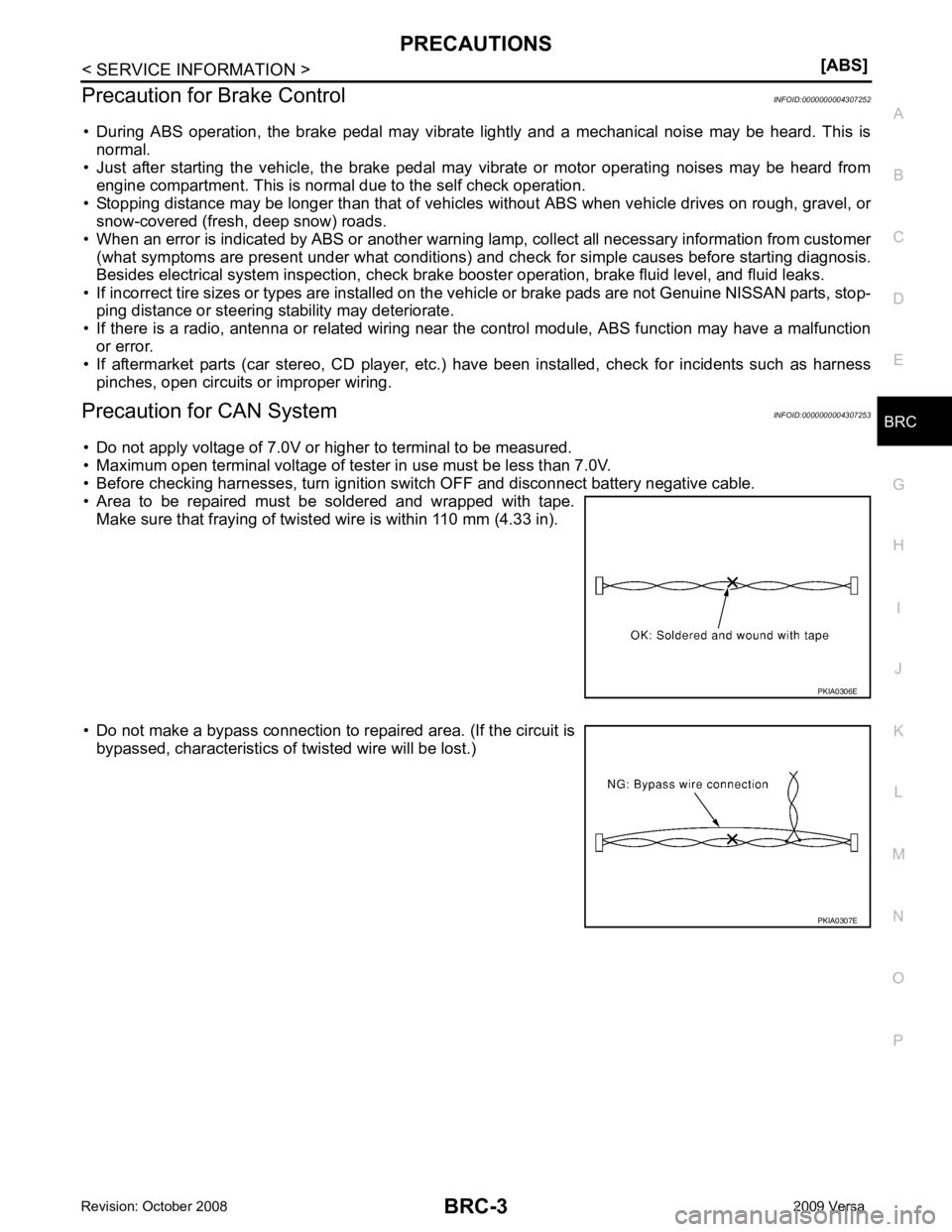
• Area to be repaired must be soldered and wrapped with tape. Make sure that fraying of twisted wire is within 110 mm (4.33 in).
• Do not make a bypass connection to repaired area. (If the circuit is bypassed, characteristics of twisted wire will be lost.)
Page 2011 of 4331
![NISSAN TIIDA 2009 Service Repair Manual DTC P0101 MAF SENSOR
EC-655
< SERVICE INFOMATION >
[MR TYPE 1] C
D E
F
G H
I
J
K L
M A EC
NP
O
DTC P0101 MAF SENSOR
Component Description INFOID:0000000004537112
The mass air flow sensor (1) is NISSAN TIIDA 2009 Service Repair Manual DTC P0101 MAF SENSOR
EC-655
< SERVICE INFOMATION >
[MR TYPE 1] C
D E
F
G H
I
J
K L
M A EC
NP
O
DTC P0101 MAF SENSOR
Component Description INFOID:0000000004537112
The mass air flow sensor (1) is](/img/5/57398/w960_57398-2010.png)
DTC P0101 MAF SENSOR
EC-655
< SERVICE INFOMATION >
[MR TYPE 1] C
D E
F
G H
I
J
K L
M A EC
NP
O
DTC P0101 MAF SENSOR
Component Description INFOID:0000000004537112
The mass air flow sensor (1) is plac ed in the stream of intake air. It
measures the intake flow rate by measuring a part of the entire
intake flow. The mass air flow sens or controls the temperature of the
hot wire to a certain amount. The heat generated by the hot wire is
reduced as the intake air flows around it. The more air, the greater
the heat loss.
Therefore, the electric current supplied to hot wire is changed to
maintain the temperature of the hot wire as air flow increases. The
ECM detects the air flow by means of this current change.
CONSULT-III Reference Val ue in Data Monitor Mode INFOID:0000000004537113
Specification data are reference values.
On Board Diagnosis Logic INFOID:0000000004537114
DTC Confirmation Procedure INFOID:0000000004537115
Perform PROCEDURE FOR MALFUNCTION A first.
If the DTC cannot be confirmed, perform PROCEDURE FOR MALFUNCTION B.
NOTE:
If DTC Confirmation Procedure has been previously conduc ted, always turn ignition switch OFF and wait at
least 10 seconds before conducting the next test. PBIA9559J
MONITOR ITEM CONDITION SPECIFICATION
MAS A/F SE-B1 • See EC-618 .
CAL/LD VALUE • Engine: After warming up
• Shift lever: P or N (A/T, CVT), Neutral (M/T)
• Air conditioner switch: OFF
• No load Idle 10% - 35%
2,500 rpm 10% - 35%
MASS AIRFLOW • Engine: After warming up
• Shift lever: P or N (A/T, CVT),
Neutral (M/T)
• Air conditioner switch: OFF
• No load Idle 1.0 - 4.0 g·m/s
2,500 rpm 4.0 - 10.0 g·m/s DTC No. Trouble diagnosis name DTC detecting condition Possible cause
P0101
0101 Mass air flow sensor cir-
cuit range/performance A)
A high voltage from the sensor is sent to ECM
under light load driving condition. • Harness or connectors
(Mass air flow sensor circuit is
open or shorted.)
• Mass air flow sensor
• EVAP control system pressure
sensor
• Intake air temperature sensor
B) A low voltage from the sensor is sent to ECM un-
der heavy load driving condition. • Harness or connectors
(Mass air flow sensor circuit is
open or shorted.)
• Intake air leaks
• Mass air flow sensor
• EVAP control system pressure sensor
• Intake air temperature sensor
Page 2019 of 4331
![NISSAN TIIDA 2009 Service Repair Manual DTC P0102, P0103 MAF SENSOR
EC-663
< SERVICE INFOMATION >
[MR TYPE 1] C
D E
F
G H
I
J
K L
M A EC
NP
O
DTC P0102, P0103 MAF SENSOR
Component Description INFOID:0000000004537121
The mass air flow se NISSAN TIIDA 2009 Service Repair Manual DTC P0102, P0103 MAF SENSOR
EC-663
< SERVICE INFOMATION >
[MR TYPE 1] C
D E
F
G H
I
J
K L
M A EC
NP
O
DTC P0102, P0103 MAF SENSOR
Component Description INFOID:0000000004537121
The mass air flow se](/img/5/57398/w960_57398-2018.png)
DTC P0102, P0103 MAF SENSOR
EC-663
< SERVICE INFOMATION >
[MR TYPE 1] C
D E
F
G H
I
J
K L
M A EC
NP
O
DTC P0102, P0103 MAF SENSOR
Component Description INFOID:0000000004537121
The mass air flow sensor (1) is plac ed in the stream of intake air. It
measures the intake flow rate by measuring a part of the entire
intake flow. The mass air flow sens or controls the temperature of the
hot wire to a certain amount. The heat generated by the hot wire is
reduced as the intake air flows around it. The more air, the greater
the heat loss.
Therefore, the electric current supplied to hot wire is changed to
maintain the temperature of the hot wire as air flow increases. The
ECM detects the air flow by means of this current change.
CONSULT-III Reference Val ue in Data Monitor Mode INFOID:0000000004537122
Specification data are reference values.
On Board Diagnosis Logic INFOID:0000000004537123
These self-diagnoses have the on e trip detection logic.
FAIL-SAFE MODE When the malfunction is detec ted, the ECM enters fail-safe mode and the MIL lights up.
DTC Confirmation Procedure INFOID:0000000004537124
NOTE:
If DTC Confirmation Procedure has been previously conduc ted, always turn ignition switch OFF and wait at
least 10 seconds before conducting the next test. PBIA9559J
MONITOR ITEM CONDITION SPECIFICATION
MAS A/F SE-B1 See EC-618 .
CAL/LD VALUE • Engine: After warming up
• Shift lever: P or N (A/T, CVT), Neutral (M/T)
• Air conditioner switch: OFF
• No load Idle 10% - 35%
2,500 rpm 10% - 35%
MASS AIRFLOW • Engine: After warming up
• Shift lever: P or N (A/T, CVT),
Neutral (M/T)
• Air conditioner switch: OFF
• No load Idle 1.0 - 4.0 g·m/s
2,500 rpm 4.0 - 10.0 g·m/s DTC No.
Trouble diagnosis
name DTC detecting condition Possible cause
P0102
0102 Mass air flow sensor
circuit low input An excessively low voltage from the sensor is sent
to ECM. • Harness or connectors
(Mass air flow sensor circuit is open or short-
ed.)
• Intake air leaks
• Mass air flow sensor
P0103
0103 Mass air flow sensor
circuit high input An excessively high voltage from the sensor is
sent to ECM. • Harness or connectors
(Mass air flow sensor circuit is open or short-
ed.)
• Mass air flow sensor Detected items Engine operating condition in fail-safe mode
Mass air flow sensor circuit Engine speed will not rise more than 2,400 rpm due to the fuel cut.
Page 2526 of 4331
![NISSAN TIIDA 2009 Service Repair Manual EC-1170< SERVICE INFOMATION >
[MR TYPE 2]
DTC P0101 MAF SENSOR
DTC P0101 MAF SENSOR
Component Description INFOID:0000000004499998
The mass air flow sensor (1) is placed in the stream of in NISSAN TIIDA 2009 Service Repair Manual EC-1170< SERVICE INFOMATION >
[MR TYPE 2]
DTC P0101 MAF SENSOR
DTC P0101 MAF SENSOR
Component Description INFOID:0000000004499998
The mass air flow sensor (1) is placed in the stream of in](/img/5/57398/w960_57398-2525.png)
EC-1170< SERVICE INFOMATION >
[MR TYPE 2]
DTC P0101 MAF SENSOR
DTC P0101 MAF SENSOR
Component Description INFOID:0000000004499998
The mass air flow sensor (1) is placed in the stream of intake air. It
measures the intake flow rate by measuring a part of the entire
intake flow. The mass air flow sensor controls the temperature of the
hot wire to a certain amount. The heat generated by the hot wire is
reduced as the intake air flows around it. The more air, the greater
the heat loss.
Therefore, the electric current supplied to hot wire is changed to
maintain the temperature of the hot wire as air flow increases. The
ECM detects the air flow by means of this current change.
CONSULT-III Reference Value in Data Monitor Mode INFOID:0000000004499999
Specification data are reference values.
On Board Diagn osis Logic INFOID:0000000004500000
DTC Confirmation Procedure INFOID:0000000004500001
Perform PROCEDURE FOR MALFUNCTION A first.
If the DTC cannot be confirmed, perform PROCEDURE FOR MALFUNCTION B.
NOTE:
If DTC Confirmation Procedure has been previously conduc ted, always turn ignition switch OFF and wait at
least 10 seconds before conducting the next test. PBIA9559J
MONITOR ITEM CONDITION SPECIFICATION
MAS A/F SE-B1 • See EC-1130 .
CAL/LD VALUE • Engine: After warming up
• Shift lever: P or N (A/T, CVT), Neutral (M/T)
• Air conditioner switch: OFF
• No load Idle 10% - 35%
2,500 rpm 10% - 35%
MASS AIRFLOW • Engine: After warming up
• Shift lever: P or N (A/T, CVT),
Neutral (M/T)
• Air conditioner switch: OFF
• No load Idle 1.0 - 4.0 g·m/s
2,500 rpm 4.0 - 10.0 g·m/s DTC No. Trouble diagnosis name DTC detecting condition Possible cause
P0101
0101 Mass air flow sensor cir-
cuit range/performance A)
A high voltage from the sensor is sent to ECM
under light load driving condition. • Harness or connectors
(Mass air flow sensor circuit is
open or shorted.)
• Mass air flow sensor
• EVAP control system pressure
sensor
• Intake air temperature sensor
B) A low voltage from the sensor is sent to ECM un-
der heavy load driving condition. • Harness or connectors
(Mass air flow sensor circuit is
open or shorted.)
• Intake air leaks
• Mass air flow sensor
• EVAP control system pressure sensor
• Intake air temperature sensor
Page 2534 of 4331
![NISSAN TIIDA 2009 Service Repair Manual EC-1178< SERVICE INFOMATION >
[MR TYPE 2]
DTC P0102, P0103 MAF SENSOR
DTC P0102, P0103 MAF SENSOR
Component Description INFOID:0000000004501157
The mass air flow sensor (1) is placed in the NISSAN TIIDA 2009 Service Repair Manual EC-1178< SERVICE INFOMATION >
[MR TYPE 2]
DTC P0102, P0103 MAF SENSOR
DTC P0102, P0103 MAF SENSOR
Component Description INFOID:0000000004501157
The mass air flow sensor (1) is placed in the](/img/5/57398/w960_57398-2533.png)
EC-1178< SERVICE INFOMATION >
[MR TYPE 2]
DTC P0102, P0103 MAF SENSOR
DTC P0102, P0103 MAF SENSOR
Component Description INFOID:0000000004501157
The mass air flow sensor (1) is placed in the stream of intake air. It
measures the intake flow rate by measuring a part of the entire
intake flow. The mass air flow sensor controls the temperature of the
hot wire to a certain amount. The heat generated by the hot wire is
reduced as the intake air flows around it. The more air, the greater
the heat loss.
Therefore, the electric current supplied to hot wire is changed to
maintain the temperature of the hot wire as air flow increases. The
ECM detects the air flow by means of this current change.
CONSULT-III Reference Value in Data Monitor Mode INFOID:0000000004501158
Specification data are reference values.
On Board Diagn osis Logic INFOID:0000000004500009
These self-diagnoses have the one trip detection logic.
FAIL-SAFE MODE
When the malfunction is detected, the ECM enters fail-safe mode and the MIL lights up.
DTC Confirmation Procedure INFOID:0000000004500010
NOTE:
If DTC Confirmation Procedure has been previously conduc ted, always turn ignition switch OFF and wait at
least 10 seconds before conducting the next test. PBIA9559J
MONITOR ITEM CONDITION SPECIFICATION
MAS A/F SE-B1 • See EC-1130 .
CAL/LD VALUE • Engine: After warming up
• Shift lever: P or N (A/T, CVT), Neutral (M/T)
• Air conditioner switch: OFF
• No load Idle 10% - 35%
2,500 rpm 10% - 35%
MASS AIRFLOW • Engine: After warming up
• Shift lever: P or N (A/T, CVT),
Neutral (M/T)
• Air conditioner switch: OFF
• No load Idle 1.0 - 4.0 g·m/s
2,500 rpm 4.0 - 10.0 g·m/s DTC No.
Trouble diagnosis
name DTC detecting condition Possible cause
P0102
0102 Mass air flow sensor
circuit low input An excessively low voltage from the sensor is sent
to ECM. • Harness or connectors
(Mass air flow sensor circuit is open or short-
ed.)
• Intake air leaks
• Mass air flow sensor
P0103
0103 Mass air flow sensor
circuit high input An excessively high voltage from the sensor is
sent to ECM. • Harness or connectors
(Mass air flow sensor circuit is open or short-
ed.)
• Mass air flow sensor Detected items Engine operating condition in fail-safe mode
Mass air flow sensor circuit Engine speed will no t rise more than 2,400 rpm due to the fuel cut.
Page 3036 of 4331
EM
NP
O
• If items or work required are not covered by the
engine section, follow the procedures in the applica-
ble sections.
• Always use the support poin t specified for lifting.
• Use either 2-pole lift type or separate type lift as best you can. If board-on type is used for unavoid-
able reasons, support at the rear axle jacking point with a transmission jack or similar tool before
starting work, in prepar ation for the backward shif t of center of gravity.
• For supporting points fo r lifting and jacking point at rear axle, refer to GI-38, " Garage Jack and
Safety Stand and 2-Pole Lift " .
REMOVAL
Outline Remove the engine and the transaxle assembly from t he vehicle downward. Separate the engine and the tran-
saxle.
Preparation 1. Remove the hood assembly. Refer to BL-14, " Removal and Installation " .
2. Remove the cowl top cover and cowl top extension assembly. Refer to EI-22, " Removal and Installation " .
3. Release fuel pressure. Refer to EC-498, " Inspection " .
4. Drain engine coolant from radiator. Refer to CO-11, " Changing Engine Coolant " .
CAUTION:
• Perform this step when the engine is cold.
• Never spill engine coolant on drive belt.
5. Drain the transmission fluid. Refer to MT-10, " Draining " (M/T),
AT-17, " Changing A/T Fluid " (A/T).
6. Remove the following parts. • Engine undercover
• Front road wheels and tires: Refer to WT-7, " Rotation " .
• Front fender protector (RH and LH): Refer to EI-24, " Removal and Installation " .
• Battery and battery tray: Refer to SC-7, " Removal and Installation " .
• Drive belt: Refer to EM-15, " Removal and Installation " .
• Air duct and air cleaner case assembly: Refer to EM-26, " Exploded View " .
• Radiator hose (upper and lower): Refer to CO-16, " Component " .
• Disconnect cooling fan controller wiring harness.
• Remove coolant reservoir tank.
• Remove fan shroud and cooling fan assembly. Refer to CO-18, " Component (Models with A/C) " or
CO- 18, " Component (Models without A/C) " .
Engine Room LH 1. Disconnect all connections of engine harness around the engine mounting insulator (LH), and then tem- porarily secure the engine harness into the engine side.
CAUTION:
Protect connectors using a resin bag against foreign materials.
2. Remove ground cable at transaxle side.
3. Disconnect fuel feed hose at engine side. Refer to EM-34, " Exploded View " .
4. Disconnect EVAP purge hose and brake booster vacuum hose.
5. Disconnect heater hoses, and install plugs them to prevent engine coolant from draining. Refer to CO-16," Component " .
6. Disconnect control linkage from transaxle. Refer to AT-212, " Control Device Removal and Installation " (A/
T), MT-13, " Exploded View " (M/T).
7. Disconnect the clutch tube at tr ansmission side (if equipped). Refer to CL-14, " Removal and Installation " .
Engine Room RH 1. Remove ground cable between front cover and vehicle.
2. Remove generator and generator bracket; Refer to SC-25, " Removal and Installation " .
3. Remove A/C compressor with piping connected from t he engine. Temporarily secure it on the vehicle side
with a rope to avoid putting load on it. (if equipped) Refer to MTC-78, " Removal and Installation of Com-
pressor - HR16DE " .
Vehicle Underbody
Page 3174 of 4331

EM
NP
O
SERVICE DATA AND SPECIFICATIONS (SDS)
Standard and Limit INFOID:0000000004307162
GENERAL SPECIFICATIONS
DRIVE BELT
WATER CONTROL VALVE
EXHAUST MANIFOLD Unit: mm (in)
THERMOSTAT
SPARK PLUG Unit: mm (in)
CYLINDER HEAD Unit: mm (in)
Engine type
MR18DE
Cylinder arrangement In-line 4
Displacement cm3
(cu in) 1,797 (109.65)
Bore and stroke mm (in) 84.0 x 81.1 (3.307 x 3.192)
Valve arrangement DOHC
Firing order 1-3-4-2
Number of piston rings Compression 2
Oil 1
Compression ratio 9.9
Compression pressure
kPa (bar, kg/cm 2
, psi) / 250 rpm Standard 1,500 (15.0, 15.3, 217.6)
Minimum 1,200 (12.0, 12.2, 174)
Differential limit between cylinders 100 (1.0, 1.0, 15) Tension of drive belt Auto adjustment by auto-tensioner
Valve opening temperature 93.5 - 96.5
°C (200 - 206 °F)
Full-open valve lift amount 8 mm/ 108 °C (0.315 in/ 226 °F)
Valve closing temperature More than 90 °C (194 °F) Items
Limit
Surface distortion Each exhaust port 0.3 (0.012)
Entire part 0.7 (0.028) Valve opening temperature 80.5 - 83.5
°C (177 - 182 °F)
Full-open valve lift amount 8 mm/ 95 °C (0.315 in/ 203 °F)
Valve closing temperature More than 77 °C (171 °F) Make
DENSO
Standard type FXE20HR11
Spark plug gap Nominal: 1.1 (0.043)Items Standard Limit
Head surface distortion — 0.1 (0.004)
Normal cylinder head height (H) 130.9 (5.15) —
Page 3241 of 4331
FSU
N
O P
FRONT SUSPENSION ASSEMBLY
On-Vehicle Inspection and Service INFOID:0000000004305863
Make sure the mounting conditions (looseness, back lash) of each component and component conditions
(wear, damage) are normal.
INSPECTION OF LOWER BALL JOINT END PLAY 1. Set front wheels in a straight-ahead position. Do not depress brake pedal.
2. Place an iron bar or similar tool bet ween transverse link and steering knuckle.
3. Measure axial end play by prying it up and down.
CAUTION:
Be careful not to damage ball joint boot. Do not damage the installation position by applying
excessive force.
STRUT INSPECTION Check for oil leakage, damage and replace as necessary.
Wheel Alignment Inspection INFOID:0000000004305864
PRELIMINARY INSPECTION WARNING:
Always adjust the alignment with the vehicle on a flat surface.
NOTE:
If alignment is out of specification, inspect and r eplace any damaged or worn rear suspension parts before
making any adjustments.
1. Check and adjust the wheel alignment with the vehicle under unladen conditions. “Unladen conditions”
means that the fuel, coolant, and lubricant are full; and that the spare tire, jack, hand tools and mats are in
their designated positions.
2. Check the tires for incorrect air pressure and excessive wear.
3. Check the wheels for run out and damage. Refer to WT-6, " Inspection " .
4. Check the wheel bearing axial end play. Refer to FAX-6, " On-Vehicle Inspection and Service " .
5. Check the shock absorbers for leaks or damage.
6. Check each mounting point of the suspension components for any excessive looseness or damage.
7. Check each link, arm, and the suspension member for any damage.
8. Check the vehicle height. Refer to FSU-19, " Wheelarch Height (Unladen*) " .
GENERAL INFORMATION AND RECOMMENDATIONS 1. A Four-Wheel Thrust Alignment should be performed. • This type of alignment is re commended for any NISSAN vehicle.
• The four-wheel “thrust” process helps ensure that the vehicle is properly aligned and the steering wheel
is centered.
• The alignment machine itself should be ca pable of accepting any NISSAN vehicle.
• The alignment machine should be checked to ensure that it is level.
2. Make sure the alignment machine is properly calibrated. • Your alignment machine should be regularly calib rated in order to give correct information.
• Check with the manufacturer of your specific a lignment machine for their recommended Service/Cali-
bration Schedule.
THE ALIGNMENT PROCESS IMPORTANT: Use only the alignment specifications listed in this Service Manual. Refer to FSU-17, " Wheel
Alignment (Unladen*) " .
1. When displaying the alignment settings, many alignm ent machines use “indicators”: (Green/red, plus or
minus, Go/No Go). Do NOT use these indicators.
• The alignment specifications programmed into your alignment machine that operate these indicators
may not be correct. Axial end play : 0 mm (0 in)
Page 3652 of 4331
OK >> Replace IPDM E/R. Refer to
PG-27, " Removal and
Installation of IPDM E/R " .
NG >> Repair harness or connector.
Aiming Adjustment INFOID:0000000004306569
The front fog lamp is a semi-sealed beam type which uses a replaceable halogen bulb. Before performing
aiming adjustment, make sure of the following.
• Keep all tires inflated to correct pressure.
• Place vehicle on level surface.
• Set that there is no-load in vehicle other than the driv er (or equivalent weight placed in driver’s position).
Coolant, engine oil filled up to correct level and full fuel tank, spare tire, jack and tools are properly stowed.
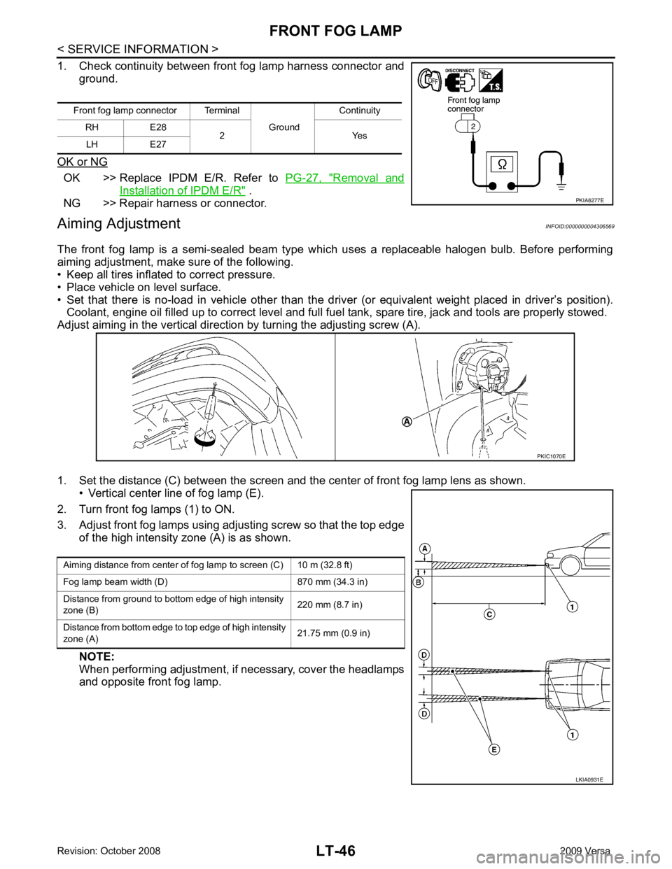
Adjust aiming in the vertical direct ion by turning the adjusting screw (A).
1. Set the distance (C) between the screen and the center of front fog lamp lens as shown. • Vertical center line of fog lamp (E).
2. Turn front fog lamps (1) to ON.
3. Adjust front fog lamps using adjusting screw so that the top edge of the high intensity zone (A) is as shown.
NOTE:
When performing adjustment, if necessary, cover the headlamps
and opposite front fog lamp.
Front fog lamp connector Terminal
Ground Continuity
RH E28 2 Yes
LH E27
Page 3789 of 4331
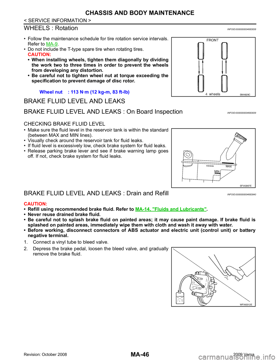
MA-46< SERVICE INFORMATION >
CHASSIS AND BODY MAINTENANCE
WHEELS : Rotation INFOID:0000000004683838
• Follow the maintenance schedule for tire rotation service intervals. Refer to MA-9 .
• Do not include the T-type spare tire when rotating tires.
CAUTION:
• When installing wheels, tighten them diagonally by dividing
the work two to three times in order to prevent the wheels
from developing any distortion.
• Be careful not to tighten wheel nut at torque exceeding the specification to prevent damage of disc rotor.
BRAKE FLUID LEVEL AND LEAKS
BRAKE FLUID LEVEL AND LEAK S : On Board Inspection INFOID:0000000004683839
CHECKING BRAKE FLUID LEVEL
• Make sure the fluid level in the reservoir tank is within the standard (between MAX and MIN lines).
• Visually check around the reservoir tank for fluid leaks.
• If fluid level is excessively low, check brake system for fluid leaks.
• Release parking brake lever and see if brake warning lamp goes off. If not, check brake system for fluid leaks.
BRAKE FLUID LEVEL AND LE AKS : Drain and Refill INFOID:0000000004683840
CAUTION:
• Refill using recommended brake fluid. Refer to MA-14, " Fluids and Lubricants " .
• Never reuse drained brake fluid.
• Be careful not to splash brake fluid on painted areas; it may cause paint damage. If brake fluid is
splashed on painted areas, immediately wipe th em with cloth and wash it away with water.
• Before working, disconnect connectors of ABS actua tor and electric unit (control unit) or battery
negative terminal.
1. Connect a vinyl tube to bleed valve.
2. Depress the brake pedal, loosen the bleed valve, and gradually remove the brake fluid.Wheel nut : 113 N·m (12 kg-m, 83 ft-lb) SMA829C
SFIA3067E
WFIA0512E