Fuse NISSAN TIIDA 2010 Service User Guide
[x] Cancel search | Manufacturer: NISSAN, Model Year: 2010, Model line: TIIDA, Model: NISSAN TIIDA 2010Pages: 3745, PDF Size: 73.67 MB
Page 418 of 3745
![NISSAN TIIDA 2010 Service User Guide AUDIOAV-21
< SERVICE INFORMATION > [AUDIO WITHOUT NAVIGATION]
C
D
E
F
G H
I
J
L
M A
B
AV
N
O P
NOTE:
Noise resulting from variations in field strength, such as fading noise and multi-path noise, or e](/img/5/57397/w960_57397-417.png "NISSAN TIIDA 2010 Service User Guide AUDIOAV-21
< SERVICE INFORMATION > [AUDIO WITHOUT NAVIGATION]
C
D
E
F
G H
I
J
L
M A
B
AV
N
O P
NOTE:
Noise resulting from variations in field strength, such as fading noise and multi-path noise, or e")
AUDIOAV-21
< SERVICE INFORMATION > [AUDIO WITHOUT NAVIGATION]
C
D
E
F
G H
I
J
L
M A
B
AV
N
O P
NOTE:
Noise resulting from variations in field strength, such as fading noise and multi-path noise, or external noise
from trains and other sources. It is not a malfunction.
• Fading noise: This noise occurs because of variations in the field strength in a narrow range due to moun-
tains or buildings blocking the signal.
• Multi-path noise: This noise results from the waves sent directly from the broadcast station arriving at the antenna at a different time from the waves t hat reflect off of mountains or buildings.
Noise InspectionINFOID:0000000005395318
The vehicle itself can be a source of noise if noise prevention parts or electrical equipment is malfunctioning.
Check if noise is caused and/or changed by engine speed, ignition switch turned to each position, and opera-
tion of each piece of electrical equipment, and determine the cause.
NOTE:
The source of the noise can be found easily by listening to the noise while removing the fuses of electrical
components, one by one.
TYPE OF NOISE AND POSSIBLE CAUSE
No sound can be heard from one or several speakers. • Open or short in audio signal circuit between audio unit and front
speaker. Refer to AV- 2 4 , "
Sound Is Not Heard from Front Door
Speaker (Base System)" or AV- 2 6 , "Sound Is Not Heard from
Front Door Speaker or Tweeter (Premium System)" .
• Front speaker. Refer to AV- 2 4 , "
Sound Is Not Heard from Front
Door Speaker (Base System)" or AV- 2 6 , "Sound Is Not Heard
from Front Door Speaker or Tweeter (Premium System)" .
• Open or short in audio signal circuit between audio unit and rear
speaker. Refer to AV- 2 5 , "
Sound Is Not Heard from Rear Door
Speaker (Base System)" or AV- 2 7 , "Sound Is Not Heard from
Rear Door Speaker (Premium System)" .
• Rear speaker. Refer to AV- 2 5 , "
Sound Is Not Heard from Rear
Door Speaker (Base System)" or AV- 2 7 , "Sound Is Not Heard
from Rear Door Speaker (Premium System)" .
• Tweeter (mid level and premium system) AV- 2 6 , "
Sound Is Not
Heard from Front Door Speaker or Tweeter (Premium System)"
or AV- 2 7 , "
Sound Is Not Heard from Rear Door Speaker (Premi-
um System)" .
• Audio unit. Refer to AV- 2 9 , "
Removal and Installation" .
No sound can be heard from radio or noise is heard. • Antenna feeder. Refer to
AV- 3 3
.
• Antenna. Refer to AV- 3 3
.
• Audio unit. Refer to AV- 2 9 , "
Removal and Installation" .
Symptom
Check item
Occurrence condition Possible cause
Occurs only when engine is ON. A continuous growling noise occurs. The speed of
the noise varies with changes in the engine speed.
Ignition components
A whistling noise occurs while the engine speed is
high. A booming noise occurs while the engine is
running and the lighting switch is ON. Generator
Noise only occurs when various
electrical components are oper-
ating. A cracking or snapping sound occurs with the op-
eration of various switches.
Relay malfunction, radio malfunction
The noise occurs when various motors are operat-
ing. • Motor case ground
•Motor
The noise occurs constantly, not just under certain conditions. • Rear defogger coil malfunction
• Open circuit in printed heater
A cracking or snapping sound occurs while the vehicle is being driven, especially when
it is vibrating excessively. • Ground wire of body parts.
• Ground due to improper part installation
• Wiring connections or a short circuit
Revision: January 20102010 Versa
Page 419 of 3745
![NISSAN TIIDA 2010 Service User Guide AV-22
< SERVICE INFORMATION >[AUDIO WITHOUT NAVIGATION]
AUDIO
Power Supply Circuit Inspection
INFOID:0000000005395319
1.CHECK FUSE
Check that the following fuses of the audio unit are not blown.
OK or](/img/5/57397/w960_57397-418.png "NISSAN TIIDA 2010 Service User Guide AV-22
< SERVICE INFORMATION >[AUDIO WITHOUT NAVIGATION]
AUDIO
Power Supply Circuit Inspection
INFOID:0000000005395319
1.CHECK FUSE
Check that the following fuses of the audio unit are not blown.
OK or")
AV-22
< SERVICE INFORMATION >[AUDIO WITHOUT NAVIGATION]
AUDIO
Power Supply Circuit Inspection
INFOID:0000000005395319
1.CHECK FUSE
Check that the following fuses of the audio unit are not blown.
OK or NG
OK >> GO TO 2.
NG >> If fuse is blown, be sure to eliminate cause of blown fuse before installing new fuse. Refer to PG-
4 .
2.AUDIO UNIT POWER SUPPLY CIRCUIT CHECK
1. Disconnect audio unit connector.
2. Check voltage between the audio unit and ground.
OK or NG
OK >> With premium system, GO TO 3.
NG >> • Check connector housings for disconnected or loose
terminals.
• Repair harness or connector.
3.GROUND CIRCUIT CHECK
Check continuity between audio uni t (premium system) harness con-
nectors M43 (A), M44 (B) terminals 20, 61 and ground.
OK or NG
OK >> Inspection End.
NG >> • Check connector housings for disconnected or loose
terminals.
• Repair harness or connector.
Steering Switch Check (With Bluetooth)INFOID:0000000005395324
1.CHECK HARNESS
1. Turn ignition switch OFF.
2. Disconnect Bluetooth control unit connector and spiral cable connector M30.
3. Check continuity between Bluetooth control unit (A) connector B121 terminals 12, 14, and 13 and spiral
cable (B) connector M30 terminals 24, 31, and 32.
Unit Terminals Signal name Fuse No.
Audio unit 19
Battery power 27
7 Ignition switch ACC or ON 20
UnitTe r m i n a l N o .
OFF ACC ON
(+)
(-)
Connector Terminal
Audio unit M43 19 Ground
Battery
voltage Battery
voltage Battery
voltage
7Ground0V Battery
voltage Battery
voltage
WKIA5345E
Continuity should exist.
AWNIA2078ZZ
Revision: January 20102010 Versa
Page 439 of 3745
![NISSAN TIIDA 2010 Service User Guide AV-42
< SERVICE INFORMATION >[AUDIO WITHOUT NAVIGATION]
TELEPHONE
Power Supply and Ground Circuit Inspection for Bluetooth Control Unit
INFOID:0000000005395340
1.CHECK FUSES
Make sure the following fu](/img/5/57397/w960_57397-438.png "NISSAN TIIDA 2010 Service User Guide AV-42
< SERVICE INFORMATION >[AUDIO WITHOUT NAVIGATION]
TELEPHONE
Power Supply and Ground Circuit Inspection for Bluetooth Control Unit
INFOID:0000000005395340
1.CHECK FUSES
Make sure the following fu")
AV-42
< SERVICE INFORMATION >[AUDIO WITHOUT NAVIGATION]
TELEPHONE
Power Supply and Ground Circuit Inspection for Bluetooth Control Unit
INFOID:0000000005395340
1.CHECK FUSES
Make sure the following fuses for the Bluetooth control unit are not blown.
OK or NG
OK >> GO TO 2.
NG >> If fuse is blown, be sure to eliminate cause of malfunction before installing new fuse. Refer to PG-
4.
2.CHECK POWER SUPPLY CIRCUIT
1. Disconnect Bluetooth control unit connector B121.
2. Check voltage between connector terminals and ground as fol- lows.
OK or NG
OK >> GO TO 3.
NG >> Check harness for open between Bluetooth control unit and fuse.
3.CHECK GROUND CIRCUITS
1. Turn ignition switch OFF.
2. Check continuity between the following Bluetooth control unit terminals and ground.
OK or NG
OK >> Inspection End.
NG >> Repair or replace harness.
Steering Wheel Audio Control Switch Does Not OperateINFOID:0000000005395342
1.CHECK STEERING WHEEL AUDIO CONTROL SWITCH RESISTANCE
1. Turn ignition switch OFF.
2. Disconnect steering wheel audio control switch connector.
Te r m i n a l s Ignition Switch Fuse No.
Connector Terminal
B121 1
All positions27
2 ACC/ON20
3 ON/START3
Terminals Ignition switch position
(+) (–) OFF ACC ON
Connector Terminal
B121 1
Ground Battery
voltage Battery
voltage Battery
voltage
20 VBattery
voltage Battery
voltage
30 V0V Battery
voltage
WKIA4389E
Te r m i n a l s Continuity
Connector Terminal—
B121 4
Ground Yes
20
21
23
LKIA0794E
Revision: January 20102010 Versa
Page 450 of 3745
![NISSAN TIIDA 2010 Service User Guide AUDIOAV-53
< SERVICE INFORMATION > [AUDIO WITH NAVIGATION]
C
D
E
F
G H
I
J
L
M A
B
AV
N
O P
System DescriptionINFOID:0000000005988543
AUDIO SYSTEM
Refer to Owners Manual for audio system operating in](/img/5/57397/w960_57397-449.png "NISSAN TIIDA 2010 Service User Guide AUDIOAV-53
< SERVICE INFORMATION > [AUDIO WITH NAVIGATION]
C
D
E
F
G H
I
J
L
M A
B
AV
N
O P
System DescriptionINFOID:0000000005988543
AUDIO SYSTEM
Refer to Owners Manual for audio system operating in")
AUDIOAV-53
< SERVICE INFORMATION > [AUDIO WITH NAVIGATION]
C
D
E
F
G H
I
J
L
M A
B
AV
N
O P
System DescriptionINFOID:0000000005988543
AUDIO SYSTEM
Refer to Owner's Manual for audio system operating instructions.
Navigation is built into AV control unit.
This navigation has the following functions.
• Full support for playback of music from iPod
® and USB device.
• High resolution full color touch panel 5 “WQVGA” display.
• FM/AM twin digital tuner.
• USB mass storage.
• XM traffic.
• POI Support is included. User POI download.
Power is supplied at all times
• through 20A fuse (No. 27, located in the fuse and fusible link box)
• to AV control unit terminal 19.
With the ignition switch in the ACC or ON position, power is supplied
• through 10A fuse [No. 20, located in the fuse block (J/B)]
• to AV control unit terminal 7.
Ground is supplied to
• to AV control unit terminals 20 and 32
• through grounds M57 and M61.
Then audio signals are supplied
• through AV control unit terminals 2, 3, 4, 5, 11, 12, 13 and 14
• to terminals + and - of front door speaker LH and RH
• to terminals + and - of front tweeter LH and RH and
• to terminals + and - of rear door speaker LH and RH.
STEERING WHEEL AUDIO CONTROL SWITCHES
When one of steering wheel audio control switches is pus hed, the resistance in steering switch circuit changes
depending on which button is pushed.
AWNIA2215GB
Revision: January 20102010 Versa
Page 464 of 3745
![NISSAN TIIDA 2010 Service User Guide AUDIOAV-67
< SERVICE INFORMATION > [AUDIO WITH NAVIGATION]
C
D
E
F
G H
I
J
L
M A
B
AV
N
O P
MALFUNCTION WITH AUXILIARY INPUT
NOTE:
Check that there is no malfunction of AUX equipment main body before](/img/5/57397/w960_57397-463.png "NISSAN TIIDA 2010 Service User Guide AUDIOAV-67
< SERVICE INFORMATION > [AUDIO WITH NAVIGATION]
C
D
E
F
G H
I
J
L
M A
B
AV
N
O P
MALFUNCTION WITH AUXILIARY INPUT
NOTE:
Check that there is no malfunction of AUX equipment main body before")
AUDIOAV-67
< SERVICE INFORMATION > [AUDIO WITH NAVIGATION]
C
D
E
F
G H
I
J
L
M A
B
AV
N
O P
MALFUNCTION WITH AUXILIARY INPUT
NOTE:
Check that there is no malfunction of AUX equipment main body before performing a diagnosis.
MALFUNCTION WITH STEERING SWITCH
AV Control Unit Power and Ground Supply Circuit InspectionINFOID:0000000005988548
1.CHECK FUSE
Check that the following fuses of the AV control unit are not blown.
OK or NG
OK >> GO TO 2.
NG >> If fuse is blown, be sure to eliminate cause of malfunction before installing new fuse. Refer to AV-
54.
2.AV CONTROL UNIT POWER SUPPLY CIRCUIT CHECK
1. Disconnect AV control unit connector.
2. Check voltage between the AV control unit connector and ground.
Symptoms Check itemsProbable malfunction location / Action to
take
iPod
® or USB memory can not be
recognized. With iPod
® or USB
memory Connected,
check “USB Device” in
“SERVICE STATUS”,
“SERVICE MENU”. iPod
® or USB memory
name is displayed for
“USB Device”. • USB interface and AUX jack harness
• USB interface and AUX jack. Refer to
AV- 8 9
.
• AV control unit. Refer to AV- 7 2
.
“Removed” is displayed
for “USB Device”. • USB interface and AUX jack harness
• USB interface and AUX jack. Refer to
AV- 8 9
.
—— Generation of iPod
® not supported
SymptomsCheck items Probable malfunction location
No voice sound is heard when
AUX mode is selected. Voice sound is heard when other modes
are selected. • USB interface and AUX jack harness
• USB interface and AUX jack. Refer to AV- 8 9
.
Symptoms
Possible malfunction location / Action to take
All steering switches are not operated.
Steering switch. Refer to AV- 6 8
.
Only specified switch cannot be operated.
“SEEK UP”, “VOL UP” and “SOURCE” switches are not
operated.
“SOURCE”, “SEEK DOWN” and “VOL DOWN” switches
are not operated.
Unit
Terminals Signal name Fuse No.
AV control unit 19
Battery power 27
7 Ignition switch ACC or ON 20
Revision: January 20102010 Versa
Page 479 of 3745
![NISSAN TIIDA 2010 Service User Guide AV-82
< SERVICE INFORMATION >[AUDIO WITH NAVIGATION]
TELEPHONE
Workflow
INFOID:0000000005924431
Power Supply and Ground Circuit Inspection for Bluetooth Control UnitINFOID:0000000005924432
1.CHECK FUS](/img/5/57397/w960_57397-478.png "NISSAN TIIDA 2010 Service User Guide AV-82
< SERVICE INFORMATION >[AUDIO WITH NAVIGATION]
TELEPHONE
Workflow
INFOID:0000000005924431
Power Supply and Ground Circuit Inspection for Bluetooth Control UnitINFOID:0000000005924432
1.CHECK FUS")
AV-82
< SERVICE INFORMATION >[AUDIO WITH NAVIGATION]
TELEPHONE
Workflow
INFOID:0000000005924431
Power Supply and Ground Circuit Inspection for Bluetooth Control UnitINFOID:0000000005924432
1.CHECK FUSES
Make sure the following fuses for the Bluetooth control unit are not blown.
OK or NG
OK >> GO TO 2.
NG >> If fuse is blown, be sure to eliminate cause of malfunction before installing new fuse. Refer to PG-
4.
2.CHECK POWER SUPPLY CIRCUIT
1. Disconnect Bluetooth control unit connector B121.
2. Check voltage between connector terminals and ground as fol- lows.
OK or NG
OK >> GO TO 3.
NG >> Check harness for open between Bluetooth control unit and fuse.
3.CHECK GROUND CIRCUITS
1. Turn ignition switch OFF.
Failure Message Action
“Internal failure” Replace Bluetooth control unit. Refer to AV- 8 5 , "
Removal and Installation".
“Bluetooth antenna open” 1. Inspect harness connection.
2. Replace Bluetooth antenna. Refer to AV- 8 5 , "
Removal and Installation".
“Bluetooth antenna shorted”
“Phone/Send for Hands Free System is stuck” Check steering wheel audio control switches. Refer to AV- 6 8 , "
Steering Switch
Check".
“Phone/End for the Hands Free System is stuck”
“Microphone test” (failed interactive test) 1. Inspect harness between Bluetooth control unit and microphone.
2. Replace microphone. Refer to
AV- 8 5 , "
Removal and Installation".
Te r m i n a l s
Ignition Switch Fuse No.
Connector Terminal
B121 1
All positions27
2 ACC/ON20
3 ON/START3
Terminals Ignition switch position
(+) (–) OFF ACC ON
Connector Terminal
B121 1
Ground Battery
voltage Battery
voltage Battery
voltage
20 VBattery
voltage Battery
voltage
30 V0V Battery
voltage
WKIA4389E
Revision: January 20102010 Versa
Page 505 of 3745
BCS-16
< SERVICE INFORMATION >
BCM (BODY CONTROL MODULE)
1: With Intelligent Key
2: Without Intelligent Key
3: Hatchback without Intelligent Key
4: Sedan without Intelligent Key
5: Hatchback
6: Sedan
7: With power door locks
8: With power windows
BCM Power Supply and Ground Circuit InspectionINFOID:0000000005395108
1.CHECK FUSES AND FUSIBLE LINK
• Check 40A fusible link (letter g , located in the fuse and fusible link box).
• Check 10A fuses [No. 6, 8 and 20, lo cated in the fuse block (J/B)].
OK or NG
OK >> GO TO 2.
NG >> If fuse is blown, be sure to eliminate cause of malfunction before installing new fuse. Refer to PG-
4, "Schematic" .
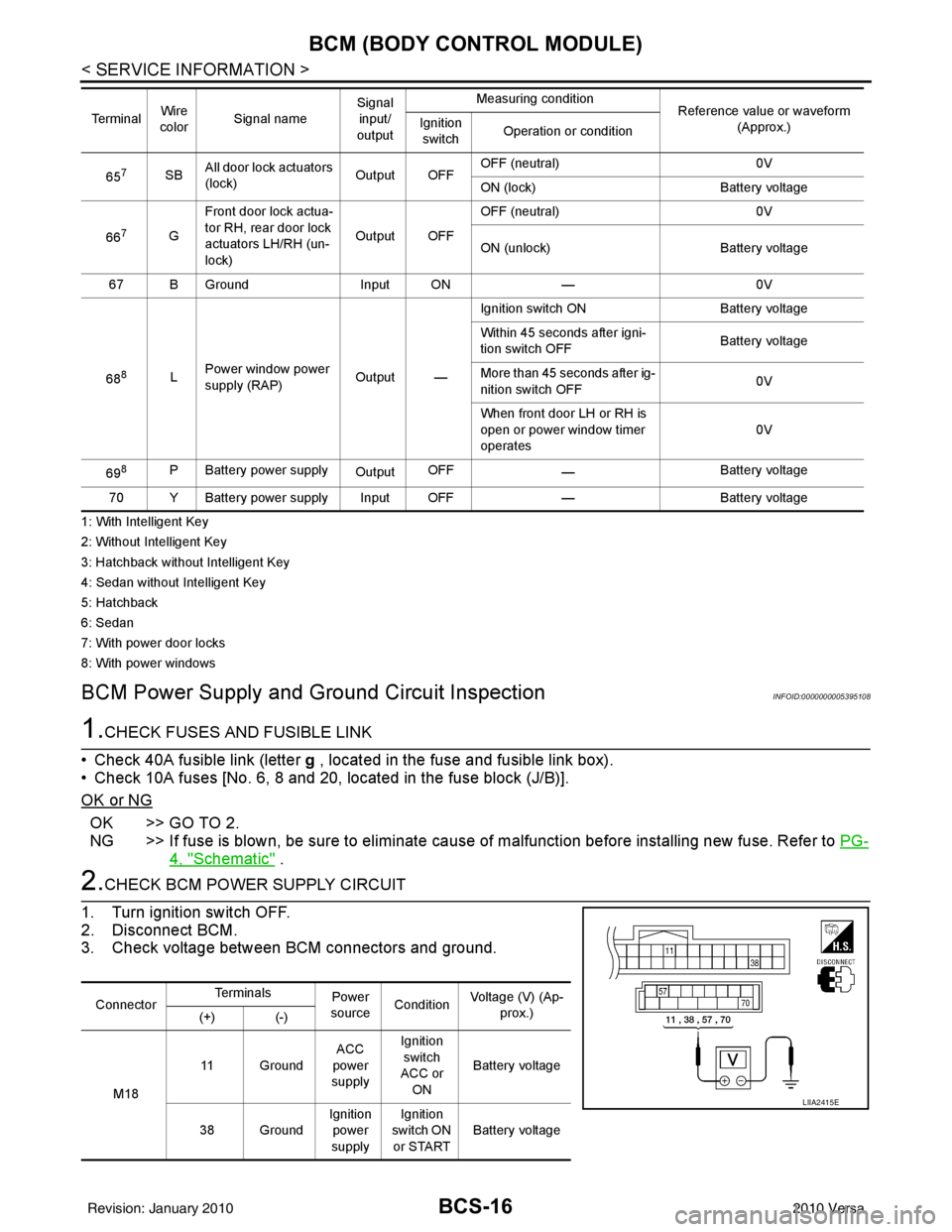
2.CHECK BCM POWER SUPPLY CIRCUIT
1. Turn ignition switch OFF.
2. Disconnect BCM.
3. Check voltage between BCM connectors and ground.
657SB All door lock actuators
(lock) Output OFFOFF (neutral)
0V
ON (lock) Battery voltage
66
7G Front door lock actua-
tor RH, rear door lock
actuators LH/RH (un-
lock) Output OFFOFF (neutral)
0V
ON (unlock) Battery voltage
67 B Ground Input ON—0V
68
8L Power window power
supply (RAP)
Output —Ignition switch ON
Battery voltage
Within 45 seconds after igni-
tion switch OFF Battery voltage
More than 45 seconds after ig-
nition switch OFF 0V
When front door LH or RH is
open or power window timer
operates 0V
69
8P Battery power supply OutputOFF
— Battery voltage
70 Y Battery power supply Input OFF —Battery voltage
Te r m i n a l
Wire
color Signal name Signal
input/
output Measuring condition
Reference value or waveform
(Approx.)
Ignition
switch Operation or condition
Connector Te r m i n a l s
Power
source Condition Voltage (V) (Ap-
prox.)
(+) (-)
M18 11 Ground
ACC
power
supply Ignition
switch
ACC or
ON Battery voltage
38 Ground Ignition
power
supply Ignition
switch ON or START Battery voltage
LIIA2415E
Revision: January 20102010 Versa
Page 532 of 3745

POWER DOOR LOCK SYSTEMBL-23
< SERVICE INFORMATION >
C
DE
F
G H
J
K L
M A
B
BL
N
O P
System DescriptionINFOID:0000000005396554
Power is supplied at all times
• through 40A fusible link (letter g , located in the fuse and fusible link box)
• to BCM terminal 70
• through 10A fuse [No. 8, located in the fuse block (J/B)]
• to BCM terminal 57
• through 10A fuse [No. 14, located in the fuse block (J/B)]
• to key switch terminal 2 (without Intelligent Key system)
• through 10A fuse [No. 31, located in the fuse block (J/B)]
• to key switch and ignition knob switch terminals 2 and 4 (with Intelligent Key system).
When key switch is ON (key is inserted in ignition key cylinder), power is supplied
• through key switch terminal 1 (without Intelligent Key system) or key switch and ignition knob terminal 1 (with Intelligent Key system)
• to BCM terminal 37.
Ground is supplied
• to BCM terminal 67
• through body grounds M57 and M61.
LOCK OPERATION
When the door is locked with main power window and door lock/unlock switch, ground is supplied
• to BCM terminal 45
• through main power window and door lock and unlock switch terminals 17 and 18
• through body grounds M57 and M61.
When the door is locked with power window and door lock/unlock switch RH, ground is supplied
• to BCM terminal 45
• through power window and door lock and unlock switch RH terminals 1 and 3
• through body grounds M57 and M61.
When the door is locked with front door ke y cylinder switch LH, ground is supplied
• to BCM terminal 8
• through front door key cylinder switch LH terminals 1 and 2
• through body grounds M57 and M61.
UNLOCK OPERATION
When the door is unlocked with main power window and door lock/unlock switch, ground is supplied
• to BCM terminal 46
• through main power window and door lock/unlock switch terminals 6 and 17
• through body grounds M57 and M61.
When the door is unlocked with power window and door lock/unlock switch RH, ground is supplied
• to BCM terminal 46
• through power window and door lock and unlock switch RH terminals 2 and 3
• through body grounds M57 and M61.
When the door is unlocked with front door ke y cylinder switch LH, ground is supplied
• to BCM terminal 7
• through front door key cylinder switch LH terminals 2 and 3
• through body grounds M57 and M61.
When the front door switch LH is ON (door is OPEN), ground is supplied
• to BCM terminal 47
• through front door switch LH terminal 2
• through front door switch LH case ground.
When the front door switch RH is ON (door is OPEN), ground is supplied
• to BCM terminal 12
• through front door switch RH terminal 2
• through front door switch RH case ground.
10. Key switch and key lock solenoid M27
(without Intelligent key) 11. Main power window and door lock/un-
lock switch D7, D8
Power window and door lock/unlock
switch RH D105 12. Fuse block (with Intelligent Key)
(view with instrument panel LH re-
moved)
13. Passenger select unlock relay M2 (with Intelligent Key) 14. Back door lock assembly (back door
switch) D405 (hatchback view with back
door open) 15. Combination meter M24
Revision: January 20102010 Versa
Page 552 of 3745
POWER DOOR LOCK SYSTEMBL-43
< SERVICE INFORMATION >
C
DE
F
G H
J
K L
M A
B
BL
N
O P
Trouble Diagnosis Symptom ChartINFOID:0000000005396563
BCM Power Supply and Gr ound Circuit InspectionINFOID:0000000005612414
1.CHECK FUSES AND FUSIBLE LINK
• Check 40A fusible link (letter g , located in the fuse and fusible link box).
• Check 10A fuses [No. 6, 8 and 20, lo cated in the fuse block (J/B)].
OK or NG
OK >> GO TO 2.
NG >> If fuse is blown, be sure to eliminate cause of malfunction before installing new fuse. Refer to PG-
4, "Schematic" .
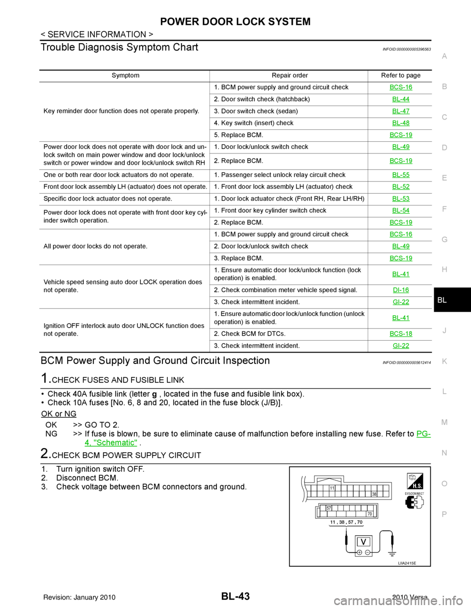
2.CHECK BCM POWER SUPPLY CIRCUIT
1. Turn ignition switch OFF.
2. Disconnect BCM.
3. Check voltage between BCM connectors and ground.
Symptom Repair orderRefer to page
Key reminder door function does not operate properly. 1. BCM power supply and ground circuit check
BCS-16
2. Door switch check (hatchback) BL-44
3. Door switch check (sedan)BL-47
4. Key switch (insert) checkBL-48
5. Replace BCM.BCS-19
Power door lock does not operate with door lock and un-
lock switch on main power window and door lock/unlock
switch or power window and door lock/unlock switch RH1. Door lock/unlock switch check
BL-49
2. Replace BCM.BCS-19
One or both rear door lock actuators do not operate. 1. Passenger select unlock relay circuit check BL-55
Front door lock assembly LH (actuator) does not operate. 1. Front door lock assembly LH (actuator) checkBL-52
Specific door lock actuator does not operate.1. Door lock actuator check (Front RH, Rear LH/RH) BL-53
Power door lock does not operate with front door key cyl-
inder switch operation.1. Front door key cylinder switch check
BL-54
2. Replace BCM.BCS-19
All power door locks do not operate.1. BCM power supply and ground circuit check
BCS-162. Door lock/unlock switch check BL-49
3. Replace BCM.BCS-19
Vehicle speed sensing auto door LOCK operation does
not operate.1. Ensure automatic door lock/unlock function (lock
operation) is enabled.
BL-41
2. Check combination meter vehicle speed signal.
DI-16
3. Check intermittent incident.GI-22
Ignition OFF interlock auto door UNLOCK function does
not operate.1. Ensure automatic door lock/unlock function (unlock
operation) is enabled.
BL-41
2. Check BCM for DTCs.
BCS-18
3. Check intermittent incident. GI-22
LIIA2415E
Revision: January 20102010 Versa
Page 558 of 3745
POWER DOOR LOCK SYSTEMBL-49
< SERVICE INFORMATION >
C
DE
F
G H
J
K L
M A
B
BL
N
O P
OK or NG
OK >> Check the following. • 10A fuse (No. 31, located in fuse and fusible linkblock)
• Harness for open or short between key switch and ignition knob switch and fuse
• Harness for open or short between BCM and key switch and ignition knob switch
NG >> Replace key switch and ignition knob switch.
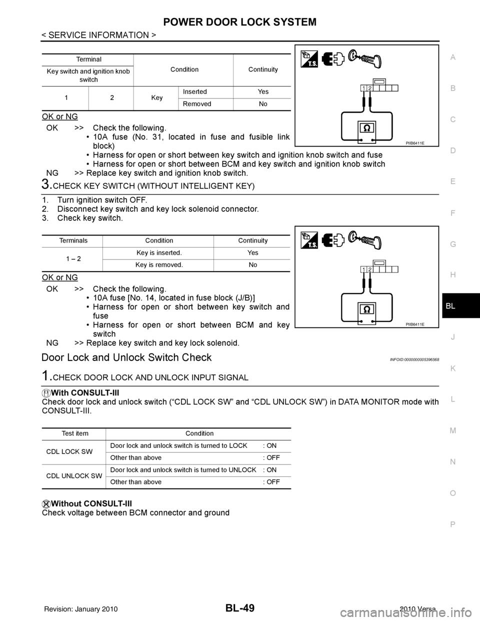
3.CHECK KEY SWITCH (WITHO UT INTELLIGENT KEY)
1. Turn ignition switch OFF.
2. Disconnect key switch and key lock solenoid connector.
3. Check key switch.
OK or NG
OK >> Check the following. • 10A fuse [No. 14, located in fuse block (J/B)]
• Harness for open or short between key switch and
fuse
• Harness for open or short between BCM and key
switch
NG >> Replace key switch and key lock solenoid.
Door Lock and Unlock Switch CheckINFOID:0000000005396568
1.CHECK DOOR LOCK AND UNLOCK INPUT SIGNAL
With CONSULT-III
Check door lock and unlock switch (“CDL LOCK SW” and “CDL UNLOCK SW”) in DATA MONITOR mode with
CONSULT-III.
Without CONSULT-III
Check voltage between BCM connector and ground
Te r m i n a l
ConditionContinuity
Key switch and ignition knob
switch
12K ey Inserted
Yes
Removed No
PIIB6411E
Terminals Condition Continuity
1 – 2 Key is inserted.
Yes
Key is removed. No
PIIB6411E
Test item Condition
CDL LOCK SW Door lock and unlock switch is turned to LOCK : ON
Other than above
: OFF
CDL UNLOCK SW Door lock and unlock switch is turned to UNLOCK : ON
Other than above
: OFF
Revision: January 20102010 Versa