fuel cap NISSAN TIIDA 2010 Service User Guide
[x] Cancel search | Manufacturer: NISSAN, Model Year: 2010, Model line: TIIDA, Model: NISSAN TIIDA 2010Pages: 3745, PDF Size: 73.67 MB
Page 1480 of 3745
P0139 HO2S2EC-215
< COMPONENT DIAGNOSIS > [HR16DE]
C
D
E
F
G H
I
J
K L
M A
EC
NP
O
P0139 HO2S2
DescriptionINFOID:0000000005398389
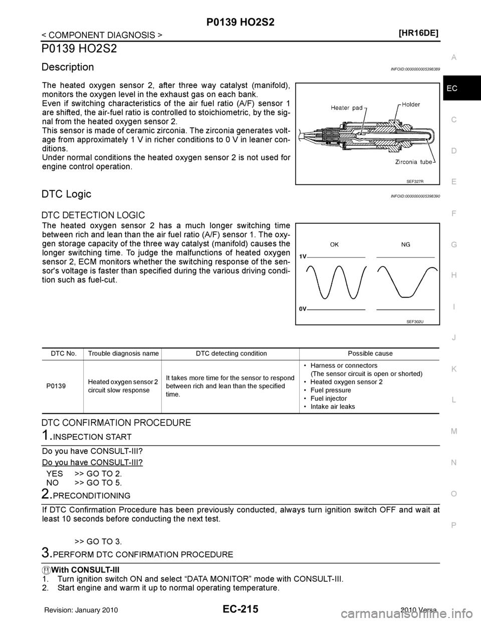
The heated oxygen sensor 2, after three way catalyst (manifold),
monitors the oxygen level in the exhaust gas on each bank.
Even if switching characteristics of the air fuel ratio (A/F) sensor 1
are shifted, the air-fuel ratio is controlled to stoichiometric, by the sig-
nal from the heated oxygen sensor 2.
This sensor is made of ceramic zirconia. The zirconia generates volt-
age from approximately 1 V in richer conditions to 0 V in leaner con-
ditions.
Under normal conditions the heated oxygen sensor 2 is not used for
engine control operation.
DTC LogicINFOID:0000000005398390
DTC DETECTION LOGIC
The heated oxygen sensor 2 has a much longer switching time
between rich and lean than the air fuel
ratio (A/F) sensor 1. The oxy-
gen storage capacity of the three way catalyst (manifold) causes the
longer switching time. To judge the malfunctions of heated oxygen
sensor 2, ECM monitors whether the switching response of the sen-
sor's voltage is faster than specified during the various driving condi-
tion such as fuel-cut.
DTC CONFIRMATION PROCEDURE
1.INSPECTION START
Do you have CONSULT-III?
Do you have CONSULT-III?
YES >> GO TO 2.
NO >> GO TO 5.
2.PRECONDITIONING
If DTC Confirmation Procedure has been previously conducted, always turn ignition switch OFF and wait at
least 10 seconds before conducting the next test.
>> GO TO 3.
3.PERFORM DTC CONFIRMATION PROCEDURE
With CONSULT-III
1. Turn ignition switch ON and select “DATA MONITOR” mode with CONSULT-III.
2. Start engine and warm it up to normal operating temperature.
SEF327R
SEF302U
DTC No. Trouble diagnosis name DTC detecting condition Possible cause
P0139 Heated oxygen sensor 2
circuit slow response It takes more time for the sensor to respond
between rich and lean than the specified
time. • Harness or connectors
(The sensor circuit is open or shorted)
• Heated oxygen sensor 2
• Fuel pressure
• Fuel injector
• Intake air leaks
Revision: January 20102010 Versa
Page 1532 of 3745
P0420 THREE WAY CATALYST FUNCTIONEC-267
< COMPONENT DIAGNOSIS > [HR16DE]
C
D
E
F
G H
I
J
K L
M A
EC
NP
O
P0420 THREE WAY CATALYST FUNCTION
DTC LogicINFOID:0000000005398434
DTC DETECTION LOGIC
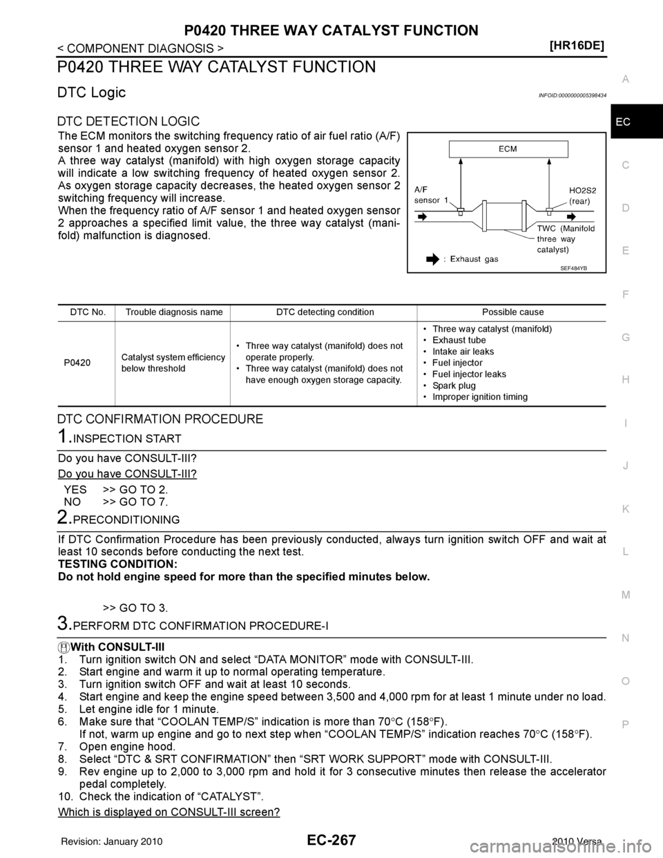
The ECM monitors the switching frequency ratio of air fuel ratio (A/F)
sensor 1 and heated oxygen sensor 2.
A three way catalyst (manifold) with high oxygen storage capacity
will indicate a low switching frequency of heated oxygen sensor 2.
As oxygen storage capacity decreases, the heated oxygen sensor 2
switching frequency will increase.
When the frequency ratio of A/F sensor 1 and heated oxygen sensor
2 approaches a specified limit value, the three way catalyst (mani-
fold) malfunction is diagnosed.
DTC CONFIRMATION PROCEDURE
1.INSPECTION START
Do you have CONSULT-III?
Do you have CONSULT-III?
YES >> GO TO 2.
NO >> GO TO 7.
2.PRECONDITIONING
If DTC Confirmation Procedure has been previously conducted, always turn ignition switch OFF and wait at
least 10 seconds before conducting the next test.
TESTING CONDITION:
Do not hold engine speed for more than the specified minutes below.
>> GO TO 3.
3.PERFORM DTC CONFIRMATION PROCEDURE-I
With CONSULT-III
1. Turn ignition switch ON and select “DATA MONITOR” mode with CONSULT-III.
2. Start engine and warm it up to normal operating temperature.
3. Turn ignition switch OFF and wait at least 10 seconds.
4. Start engine and keep the engine speed between 3,500 and 4,000 rpm for at least 1 minute under no load.
5. Let engine idle for 1 minute.
6. Make sure that “COOLAN TEMP /S” indication is more than 70°C (158°F).
If not, warm up engine and go to next step w hen “COOLAN TEMP/S” indication reaches 70 °C (158° F).
7. Open engine hood.
8. Select “DTC & SRT CONFIRMATION” then “SRT WORK SUPPORT” mode with CONSULT-III.
9. Rev engine up to 2,000 to 3,000 rpm and hold it for 3 consecutive minutes then release the accelerator
pedal completely.
10. Check the indication of “CATALYST”.
Which is displayed on CONSULT-III screen?
SEF484YB
DTC No. Trouble diagnosis name DTC detecting conditionPossible cause
P0420 Catalyst system efficiency
below threshold • Three way catalyst (manifold) does not
operate properly.
• Three way catalyst (manifold) does not
have enough oxygen storage capacity. • Three way catalyst (manifold)
• Exhaust tube
• Intake air leaks
• Fuel injector
• Fuel injector leaks
• Spark plug
• Improper ignition timing
Revision: January 20102010 Versa
Page 1543 of 3745
EC-278
< COMPONENT DIAGNOSIS >[HR16DE]
P0442 EVAP CONTROL SYSTEM
P0442 EVAP CONTROL SYSTEM
DTC LogicINFOID:0000000005398441
DTC DETECTION LOGIC
NOTE:
If DTC P0442 is displayed with DTC P0456, first pe
rform the trouble diagnosis for DTC P0456. Refer to
EC-329, "
DTC Logic".
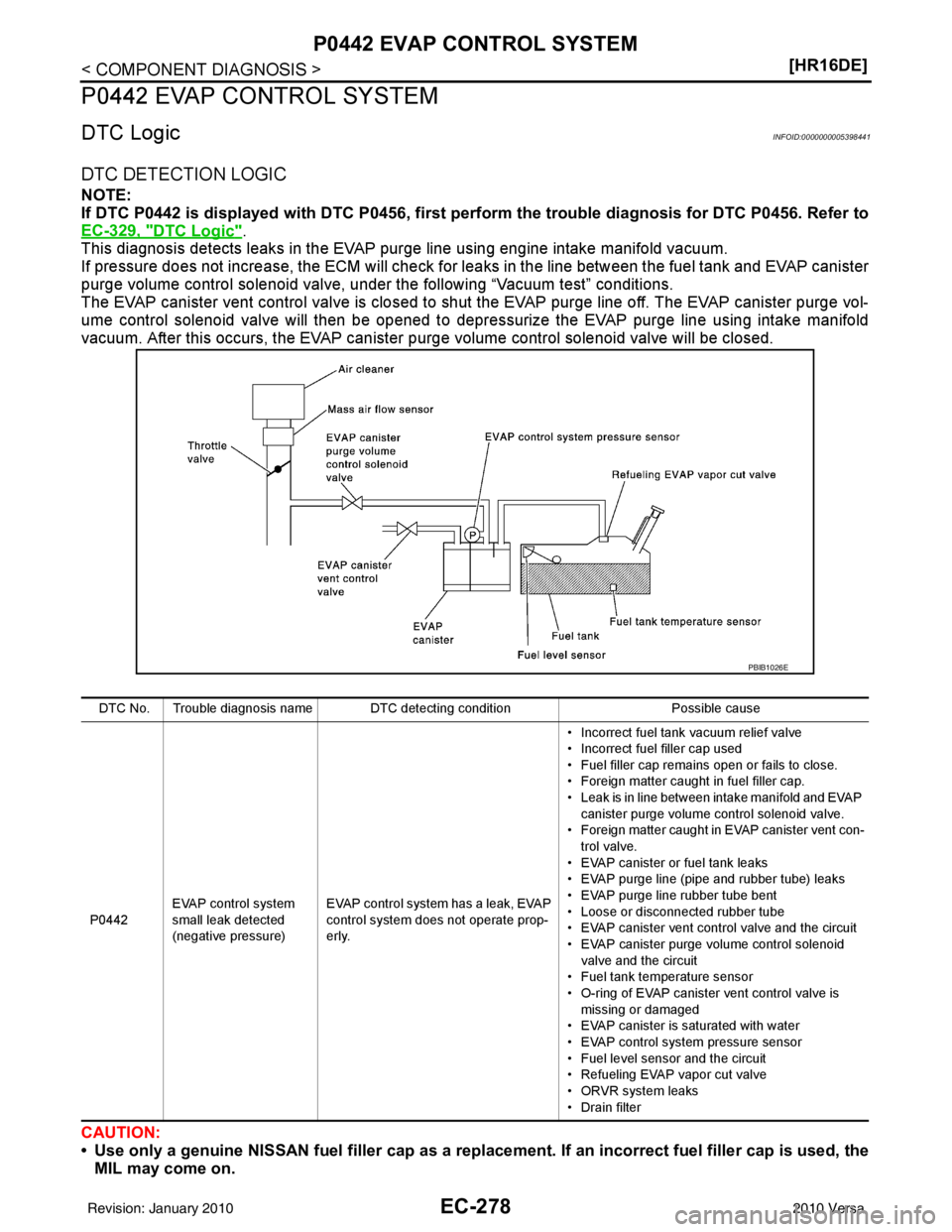
This diagnosis detects leaks in the EVAP purge line using engine intake manifold vacuum.
If pressure does not increase, the ECM will check for leaks in the line between the fuel tank and EVAP canister
purge volume control solenoid valve, under the following “Vacuum test” conditions.
The EVAP canister vent control valve is closed to shut the EVAP purge line off. The EVAP canister purge vol-
ume control solenoid valve will then be opened to depressurize the EVAP purge line using intake manifold
vacuum. After this occurs, the EVAP canister purge volume control solenoid valve will be closed.
CAUTION:
• Use only a genuine NISSAN fuel filler cap as a replacemen t. If an incorrect fuel filler cap is used, the
MIL may come on.
DTC No. Trouble diagnosis name DTC detecting condition Possible cause
P0442 EVAP control system
small leak detected
(negative pressure) EVAP control system has a leak, EVAP
control system does not operate prop-
erly. • Incorrect fuel tank vacuum relief valve
• Incorrect fuel filler cap used
• Fuel filler cap remains open or fails to close.
• Foreign matter caught in fuel filler cap.
• Leak is in line between intake manifold and EVAP
canister purge volume control solenoid valve.
• Foreign matter caught in EVAP canister vent con- trol valve.
• EVAP canister or fuel tank leaks
• EVAP purge line (pipe and rubber tube) leaks
• EVAP purge line rubber tube bent
• Loose or disconnected rubber tube
• EVAP canister vent control valve and the circuit
• EVAP canister purge volume control solenoid valve and the circuit
• Fuel tank temperature sensor
• O-ring of EVAP canister vent control valve is missing or damaged
• EVAP canister is saturated with water
• EVAP control system pressure sensor
• Fuel level sensor and the circuit
• Refueling EVAP vapor cut valve
• ORVR system leaks
• Drain filter
PBIB1026E
Revision: January 20102010 Versa
Page 1544 of 3745
P0442 EVAP CONTROL SYSTEMEC-279
< COMPONENT DIAGNOSIS > [HR16DE]
C
D
E
F
G H
I
J
K L
M A
EC
NP
O
• If the fuel filler cap is not tigh
tened properly, the MIL may come on.
• Use only a genuine NISSAN rubber tube as a replacement.
DTC CONFIRMATION PROCEDURE
1.PRECONDITIONING
If DTC Confirmation Procedure has been previously conducted, always turn ignition switch OFF and wait at
least 10 seconds before conducting the next test.
TESTING CONDITION:
• Perform “DTC WORK SUPPORT” when the fuel level is between 1/4 and 3/4 full, and vehicle is placed
on flat level surface.
• Always perform test at a temperature of 0 to 30 °C (32 to 86 °F).
NOTE:
Make sure that EVAP hoses are connected to EVAP canister purge volume control solenoid valve
properly.
Do you have CONSULT-III?
YES >> GO TO 2.
NO >> GO TO 3.
2.PERFORM DTC CONFIRMATION PROCEDURE
With CONSULT-III
1. Turn ignition switch ON.
2. Turn ignition switch OFF and wait at least 10 seconds.
3. Turn ignition switch ON and select “DATA MONITOR” mode with CONSULT-III.
4. Make sure that the following conditions are met.
COOLAN TEMP/S: 0 - 70 °C (32 - 158° F)
INT/A TEMP SE: 0 - 30 °C (32 - 86° F)
5. Select “EVAP SML LEAK P0442/P1442” of “EVAPORATIVE SYSTEM” in “DTC WORK SUPPORT” mode
with CONSULT-III.
Follow the instruction displayed.
NOTE:
If the engine speed cannot be maintained within the range displayed on the CONSULT-III screen, go to
EC-20, "
BASIC INSPECTION : Special Repair Requirement".
Which is displayed on CONSULT-III screen?
OK >> INSPECTION END
NG >> Go to EC-279, "
Diagnosis Procedure".
3.PERFORM COMPONENT FUNCTION CHECK
With GST
NOTE:
Be sure to read the explanation of DRIVING PATTERN in EC-471, "
HowtoSetSRTCode" before driving
vehicle.
1. Start engine.
2. Drive vehicle according to DRIVING PATTERN.
3. Stop vehicle.
4. Turn ignition switch OFF, wait at least 10 seconds and then turn ON.
5. Select Service $07 with GST.
Is 1st trip DTC displayed?
YES-1 >> P0441: Go to EC-274, "Diagnosis Procedure".
YES-2 >> P0442: Go to EC-279, "
Diagnosis Procedure".
NO >> INSPECTION END
Diagnosis ProcedureINFOID:0000000005398442
1.CHECK FUEL FILLER CAP DESIGN
1. Turn ignition switch OFF.
Revision: January 20102010 Versa
Page 1545 of 3745
EC-280
< COMPONENT DIAGNOSIS >[HR16DE]
P0442 EVAP CONTROL SYSTEM
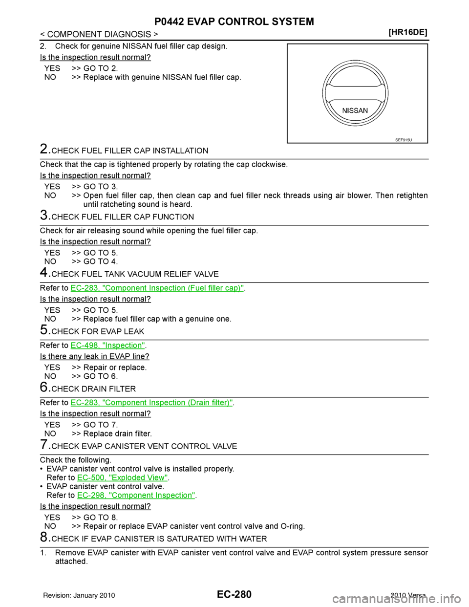
2. Check for genuine NISSAN fuel filler cap design.
Is the inspection result normal?
YES >> GO TO 2.
NO >> Replace with genuine NISSAN fuel filler cap.
2.CHECK FUEL FILLER CAP INSTALLATION
Check that the cap is tightened proper ly by rotating the cap clockwise.
Is the inspection result normal?
YES >> GO TO 3.
NO >> Open fuel filler cap, then clean cap and fuel filler neck threads using air blower. Then retighten until ratcheting sound is heard.
3.CHECK FUEL FILLER CAP FUNCTION
Check for air releasing sound while opening the fuel filler cap.
Is the inspection result normal?
YES >> GO TO 5.
NO >> GO TO 4.
4.CHECK FUEL TANK VACUUM RELIEF VALVE
Refer to EC-283, "
Component Inspection (Fuel filler cap)".
Is the inspection result normal?
YES >> GO TO 5.
NO >> Replace fuel filler cap with a genuine one.
5.CHECK FOR EVAP LEAK
Refer to EC-498, "
Inspection".
Is there any leak in EVAP line?
YES >> Repair or replace.
NO >> GO TO 6.
6.CHECK DRAIN FILTER
Refer to EC-283, "
Component Inspection (Drain filter)".
Is the inspection result normal?
YES >> GO TO 7.
NO >> Replace drain filter.
7.CHECK EVAP CANISTER VENT CONTROL VALVE
Check the following.
• EVAP canister vent control valve is installed properly. Refer to EC-500, "
Exploded View".
• EVAP canister vent control valve. Refer to EC-298, "
Component Inspection".
Is the inspection result normal?
YES >> GO TO 8.
NO >> Repair or replace EVAP cani ster vent control valve and O-ring.
8.CHECK IF EVAP CANISTER IS SATURATED WITH WATER
1. Remove EVAP canister with EVAP canister vent control valve and EVAP control system pressure sensor attached.
SEF915U
Revision: January 20102010 Versa
Page 1548 of 3745
P0442 EVAP CONTROL SYSTEMEC-283
< COMPONENT DIAGNOSIS > [HR16DE]
C
D
E
F
G H
I
J
K L
M A
EC
NP
O
NO >> Replace fuel level sensor unit.
23.CHECK INTERMITTENT INCIDENT
Refer to EC-114, "
Diagnosis Procedure".
>> INSPECTION END
Component Inspection (Fuel filler cap)INFOID:0000000005398443
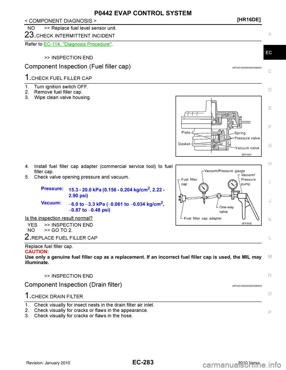
1.CHECK FUEL FILLER CAP
1. Turn ignition switch OFF.
2. Remove fuel filler cap.
3. Wipe clean valve housing.
4. Install fuel filler cap adapter (commercial service tool) to fuel filler cap.
5. Check valve opening pressure and vacuum.
Is the inspection result normal?
YES >> INSPECTION END
NO >> GO TO 2.
2.REPLACE FUEL FILLER CAP
Replace fuel filler cap.
CAUTION:
Use only a genuine fuel filler cap as a replacement. If an incorrect fuel filler cap is used, the MIL may
illuminate.
>> INSPECTION END
Component Inspection (Drain filter)INFOID:0000000005398444
1.CHECK DRAIN FILTER
1. Check visually for insect nests in the drain filter air inlet.
2. Check visually for cracks or flaws in the appearance.
3. Check visually for cracks or flaws in the hose.
SEF445Y
Pressure: 15.3 - 20.0 kPa (0.156 - 0.204 kg/cm2, 2.22 -
2.90 psi)
Vacuum: −6.0 to −3.3 kPa ( −0.061 to −0.034 kg/cm
2,
− 0.87 to −0.48 psi)
SEF943S
Revision: January 20102010 Versa
Page 1588 of 3745
P0455 EVAP CONTROL SYSTEMEC-323
< COMPONENT DIAGNOSIS > [HR16DE]
C
D
E
F
G H
I
J
K L
M A
EC
NP
O
P0455 EVAP CONTROL SYSTEM
DTC LogicINFOID:0000000005398479
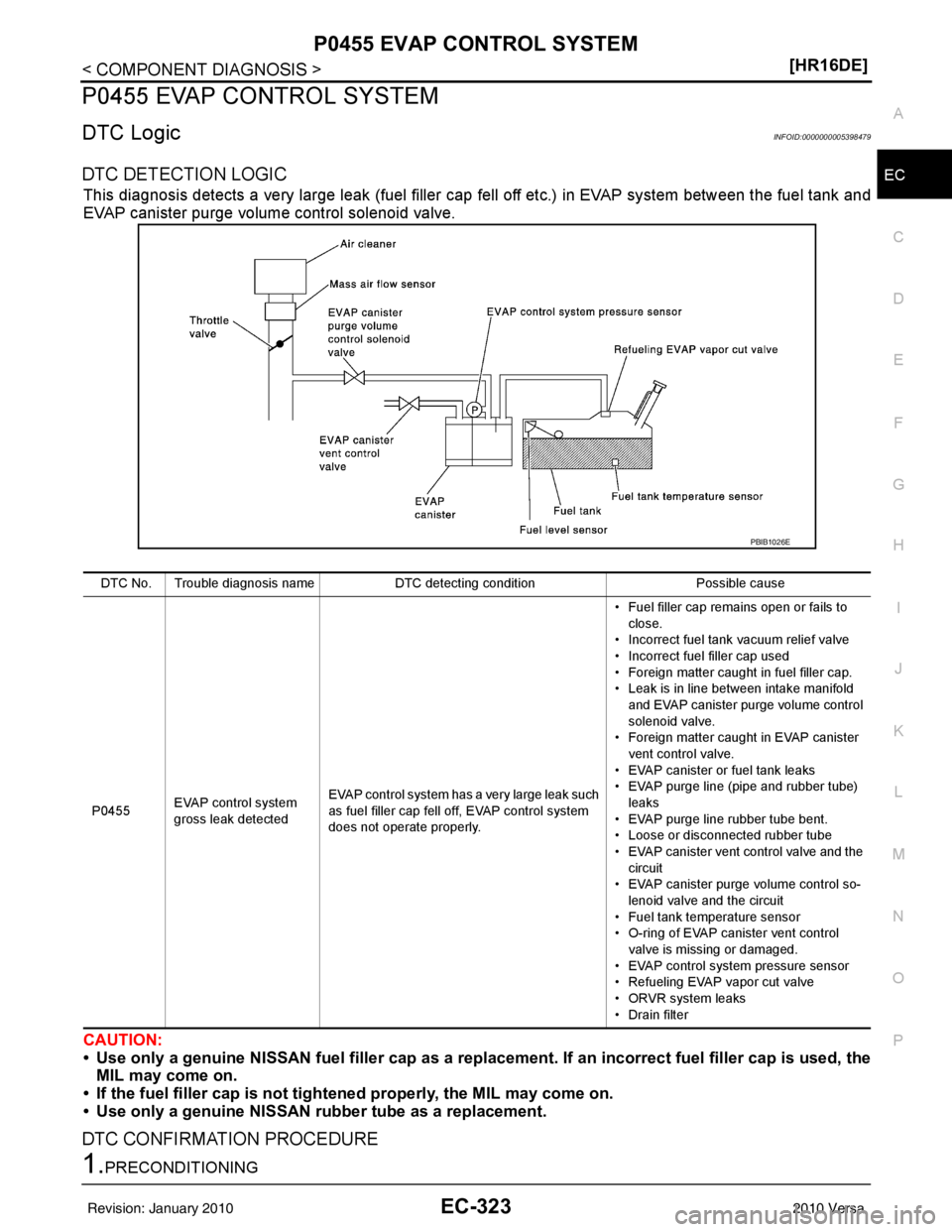
DTC DETECTION LOGIC
This diagnosis detects a very large leak (fuel filler cap
fell off etc.) in EVAP system between the fuel tank and
EVAP canister purge volume control solenoid valve.
CAUTION:
• Use only a genuine NISSAN fuel filler cap as a replacemen t. If an incorrect fuel filler cap is used, the
MIL may come on.
• If the fuel filler cap is not tigh tened properly, the MIL may come on.
• Use only a genuine NISSAN rubber tube as a replacement.
DTC CONFIRMATION PROCEDURE
1.PRECONDITIONING
DTC No. Trouble diagnosis name DTC detecting condition Possible cause
P0455 EVAP control system
gross leak detected EVAP control system has a very large leak such
as fuel filler cap fell off, EVAP control system
does not operate properly. • Fuel filler cap remains open or fails to
close.
• Incorrect fuel tank vacuum relief valve
• Incorrect fuel filler cap used
• Foreign matter caught in fuel filler cap.
• Leak is in line between intake manifold
and EVAP canister purge volume control
solenoid valve.
• Foreign matter caught in EVAP canister
vent control valve.
• EVAP canister or fuel tank leaks
• EVAP purge line (pipe and rubber tube) leaks
• EVAP purge line rubber tube bent.
• Loose or disconnected rubber tube
• EVAP canister vent control valve and the circuit
• EVAP canister purge volume control so-
lenoid valve and the circuit
• Fuel tank temperature sensor
• O-ring of EVAP canister vent control valve is missing or damaged.
• EVAP control system pressure sensor
• Refueling EVAP vapor cut valve
• ORVR system leaks
• Drain filter
PBIB1026E
Revision: January 20102010 Versa
Page 1589 of 3745
EC-324
< COMPONENT DIAGNOSIS >[HR16DE]
P0455 EVAP CONTROL SYSTEM
CAUTION:
Never remove fuel filler cap during
the DTC CONFIRMATION PROCEDURE.
If DTC Confirmation Procedure has been previously conducted, always turn ignition switch OFF and wait at
least 10 seconds before conducting the next test.
NOTE:
Make sure that EVAP hoses are connected to EVAP canister purge volume control solenoid valve
properly.
TESTING CONDITION:
• Perform “DTC WORK SUPPORT” when the fuel level is between 1/4 and 3/4 full, and vehicle is placed
on flat level surface.
• Open engine hood before conducting the following procedures.
Do you have CONSULT-III?
YES >> GO TO 2.
NO >> GO TO 4.
2.PERFORM DTC CONFIRMATION PROCEDURE
With CONSULT-III
1. Tighten fuel filler cap secure ly until ratcheting sound is heard.
2. Turn ignition switch ON.
3. Turn ignition switch OFF and wait at least 10 seconds.
4. Turn ignition switch ON and select “DATA MONITOR” mode with CONSULT-III.
5. Make sure that the following conditions are met. COOLAN TEMP/S: 0 - 70 °C (32 - 158° F)
INT/A TEMP SE: 0 - 60 °C (32 - 140° F)
6. Select “EVAP SML LEAK P0442/P1442” of “EV APORATIVE SYSTEM” in “DTC WORK SUPPORT” mode
with CONSULT-III.
Follow the instruction displayed.
NOTE:
If the engine speed cannot be maintained within t he range displayed on the CONSULT-III screen, go to
EC-20, "
BASIC INSPECTION : Special Repair Requirement".
Which is displayed on CONSULT-III screen?
OK >> INSPECTION END
NG >> GO TO 3.
3.CHECK DTC
Check DTC.
Which DTC is detected?
P0455 >> Go to EC-324, "Diagnosis Procedure".
P0442 >> Go to EC-279, "
Diagnosis Procedure".
4.PERFORM DTC CONFIRMATION PROCEDURE
With GST
NOTE:
Be sure to read the explanation of DIRVING PATTERN in EC-471, "
HowtoSetSRTCode" before driving
vehicle.
1. Start engine.
2. Drive vehicle according to DRIVING PATTERN.
3. Stop vehicle.
4. Turn ignition switch OFF, wait at least 10 seconds and then turn ON.
5. Check 1st trip DTC.
Is 1st trip DTC detected?
YES-1 >> P0455: Go to EC-324, "Diagnosis Procedure".
YES-2 >> P0442: Go to EC-279, "
Diagnosis Procedure".
YES-3 >> P0441: Go to EC-274, "
Diagnosis Procedure".
NO >> INSPECTION END
Diagnosis ProcedureINFOID:0000000005398480
1.CHECK FUEL FILLER CAP DESIGN
Revision: January 20102010 Versa
Page 1590 of 3745
P0455 EVAP CONTROL SYSTEMEC-325
< COMPONENT DIAGNOSIS > [HR16DE]
C
D
E
F
G H
I
J
K L
M A
EC
NP
O
1. Turn ignition switch OFF.
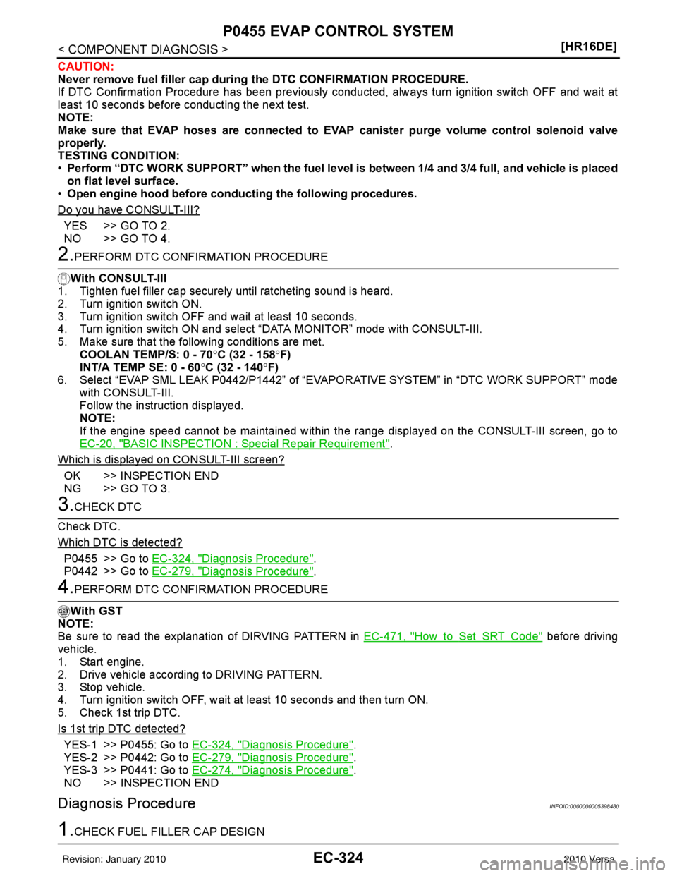
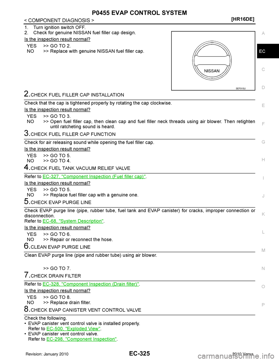
2. Check for genuine NISSAN fuel filler cap design.
Is the inspection result normal?
YES >> GO TO 2.
NO >> Replace with genuine NISSAN fuel filler cap.
2.CHECK FUEL FILLER CAP INSTALLATION
Check that the cap is tightened properly by rotating the cap clockwise.
Is the inspection result normal?
YES >> GO TO 3.
NO >> Open fuel filler cap, then clean cap and fuel fi ller neck threads using air blower. Then retighten
until ratcheting sound is heard.
3.CHECK FUEL FILLER CAP FUNCTION
Check for air releasing sound while opening the fuel filler cap.
Is the inspection result normal?
YES >> GO TO 5.
NO >> GO TO 4.
4.CHECK FUEL TANK VACUUM RELIEF VALVE
Refer to EC-327, "
Component Inspection (Fuel filler cap)".
Is the inspection result normal?
YES >> GO TO 5.
NO >> Replace fuel filler cap with a genuine one.
5.CHECK EVAP PURGE LINE
Check EVAP purge line (pipe, rubber tube, fuel tank and EVAP canister) for cracks, improper connection or
disconnection.
Refer to EC-68, "
System Description".
Is the inspection result normal?
YES >> GO TO 6.
NO >> Repair or reconnect the hose.
6.CLEAN EVAP PURGE LINE
Clean EVAP purge line (pipe and rubber tube) using air blower.
>> GO TO 7.
7.CHECK DRAIN FILTER
Refer to EC-328, "
Component Inspection (Drain filter)".
Is the inspection result normal?
YES >> GO TO 8.
NO >> Replace drain filter.
8.CHECK EVAP CANISTER VENT CONTROL VALVE
Check the following.
• EVAP canister vent control valve is installed properly. Refer to EC-500, "
Exploded View".
• EVAP canister vent control valve. Refer to EC-298, "
Component Inspection".
SEF915U
Revision: January 20102010 Versa
Page 1592 of 3745
P0455 EVAP CONTROL SYSTEMEC-327
< COMPONENT DIAGNOSIS > [HR16DE]
C
D
E
F
G H
I
J
K L
M A
EC
NP
O
NO >> Replace EVAP canister purge volume control solenoid valve.
15.CHECK FUEL TANK TEMPERATURE SENSOR
Refer to EC-238, "
Component Inspection".
Is the inspection result normal?
YES >> GO TO 16.
NO >> Replace fuel level sensor unit.
16.CHECK EVAP CONTROL SYSTEM PRESSURE SENSOR
Refer to EC-308, "
Component Inspection".
Is the inspection result normal?
YES >> GO TO 17.
NO >> Replace EVAP control system pressure sensor.
17.CHECK EVAP/ORVR LINE
Check EVAP/ORVR line between EVAP canister and fuel tank for clogging, kink, looseness and improper con-
nection. For location, refer to EC-443, "
Description".
Is the inspection result normal?
YES >> GO TO 18.
NO >> Repair or replace hoses and tubes.
18.CHECK RECIRCULATION LINE
Check recirculation line between fuel filler tube and fuel tank for clogging, kink, cracks, looseness and
improper connection.
Is the inspection result normal?
YES >> GO TO 19.
NO >> Repair or replace hose, tube or fuel filler tube.
19.CHECK REFUELING EVAP VAPOR CUT VALVE
Refer to EC-446, "
Component Inspection (Refueling EVAP vapor cut valve)".
Is the inspection result normal?
YES >> GO TO 20.
NO >> Replace refueling EVAP vapor cut valve with fuel tank.
20.CHECK INTERMITTENT INCIDENT
Refer to EC-114, "
Diagnosis Procedure".
>> INSPECTION END
Component Inspection (Fuel filler cap)INFOID:0000000005398481
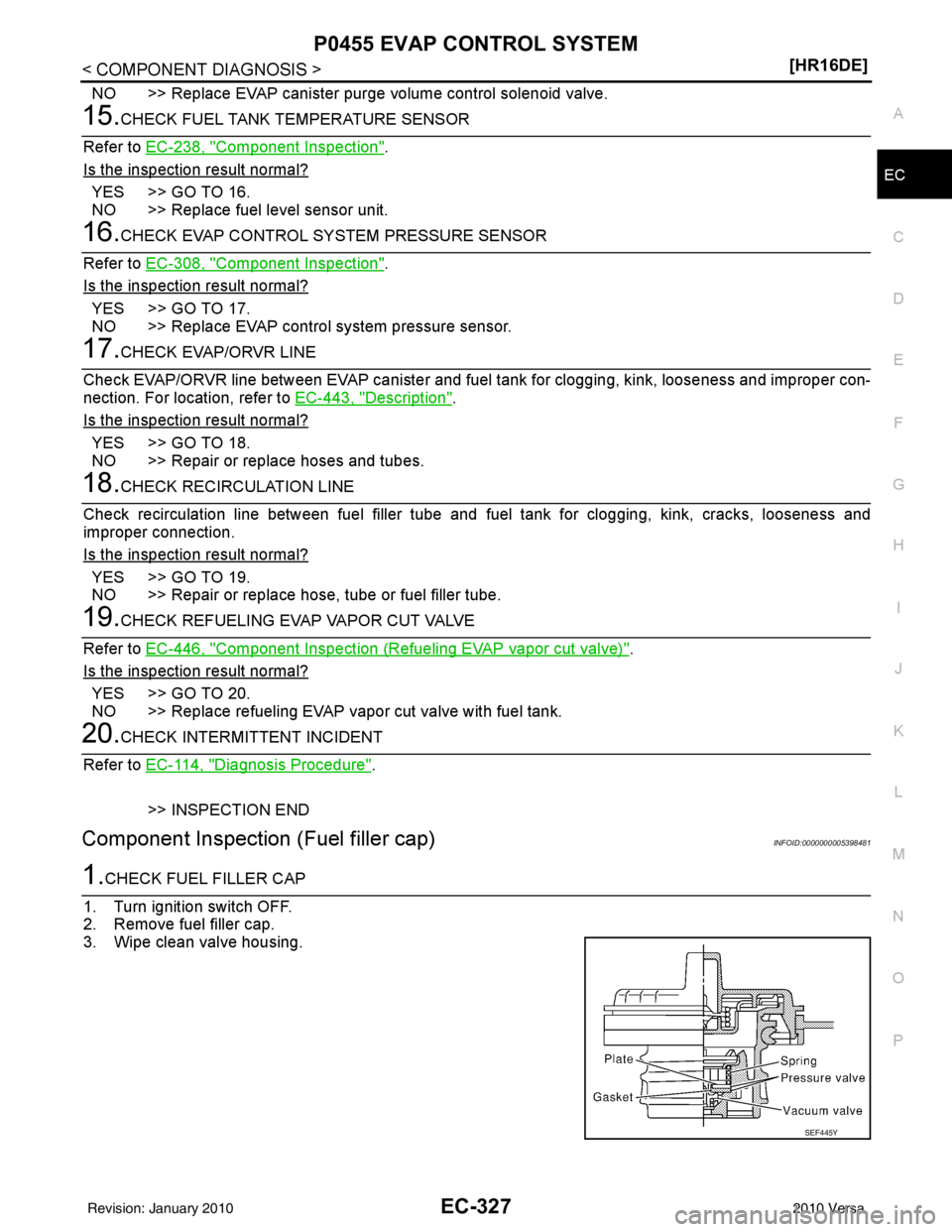
1.CHECK FUEL FILLER CAP
1. Turn ignition switch OFF.
2. Remove fuel filler cap.
3. Wipe clean valve housing.
SEF445Y
Revision: January 20102010 Versa