center console NISSAN TIIDA 2010 Service Owner's Manual
[x] Cancel search | Manufacturer: NISSAN, Model Year: 2010, Model line: TIIDA, Model: NISSAN TIIDA 2010Pages: 3745, PDF Size: 73.67 MB
Page 3198 of 3745
![NISSAN TIIDA 2010 Service Owners Manual MT-14
< SERVICE INFORMATION >[RS5F91R]
CONTROL LINKAGE
CONTROL LINKAGE
Exploded ViewINFOID:0000000005397171
Removal and InstallationINFOID:0000000005397172
REMOVAL
1. Remove the battery. Refer to
SC-](/img/5/57397/w960_57397-3197.png "NISSAN TIIDA 2010 Service Owners Manual MT-14
< SERVICE INFORMATION >[RS5F91R]
CONTROL LINKAGE
CONTROL LINKAGE
Exploded ViewINFOID:0000000005397171
Removal and InstallationINFOID:0000000005397172
REMOVAL
1. Remove the battery. Refer to
SC-")
MT-14
< SERVICE INFORMATION >[RS5F91R]
CONTROL LINKAGE
CONTROL LINKAGE
Exploded ViewINFOID:0000000005397171
Removal and InstallationINFOID:0000000005397172
REMOVAL
1. Remove the battery. Refer to
SC-7, "Removal and Installation".
2. Remove the air duct and air cleaner case. Refer to EM-26, "
Removal and Installation" .
3. Press the release button (1) of select cable and shift cable, and
then remove select cable and shift cable from select lever of
control shaft (2).
4. Move shift lever to neutral position.
5. Remove shift lever handle.
6. Remove center console assembly. Refer to IP-12, "
Removal and
Installation".
7. Remove M/T shift selector assembly bolts.
8. Remove exhaust front tube, center muffler and heat plate. Refer to EX-6, "
Removal and Installation".
9. Remove cable support bracket.
10. Remove select cable and shift cable from cable mounting bracket.
11. Remove M/T shift selector assembly from the vehicle.
INSTALLATION
Installation is in the reverse order of removal.
1. Shift lever handle 2. Shift lever3. M/T shift selector assembly
4. Select cable 5. Shift cable6. Clutch housing
7. Cable mounting bracket 8. Bracket
A: Black color B: White color
PCIB1508E
SCIA7077E
Revision: January 20102010 Versa
Page 3243 of 3745
![NISSAN TIIDA 2010 Service Owners Manual CONTROL LINKAGEMT-59
< SERVICE INFORMATION > [RS6F94R]
D
E
F
G H
I
J
K L
M A
B
MT
N
O P
b. Pull the release button (1) of select cable (2) and then remove it from control shaft select lever (3).
5. Mo](/img/5/57397/w960_57397-3242.png "NISSAN TIIDA 2010 Service Owners Manual CONTROL LINKAGEMT-59
< SERVICE INFORMATION > [RS6F94R]
D
E
F
G H
I
J
K L
M A
B
MT
N
O P
b. Pull the release button (1) of select cable (2) and then remove it from control shaft select lever (3).
5. Mo")
CONTROL LINKAGEMT-59
< SERVICE INFORMATION > [RS6F94R]
D
E
F
G H
I
J
K L
M A
B
MT
N
O P
b. Pull the release button (1) of select cable (2) and then remove it from control shaft select lever (3).
5. Move shift lever to neutral position.
6. Remove shift lever handle.
7. Remove center console assembly. Refer to IP-12, "
Removal and
Installation".
8. Remove M/T shift selector assembly bolts.
9. Remove exhaust front tube, cent er muffler and heat plate. Refer
to EX-11, "
Removal and Installation".
10. Remove cable support bracket.
11. Remove select cable and shif t cable from cable bracket.
12. Remove M/T shift selector assembly from the vehicle.
INSTALLATION
Installation is in the reverse order of removal.
NOTE:
Self tapping bolts are used to attach cables to the clutch housing.
• Securely assemble each cable and lever of control shaft.
• Be careful about the installation direction, and push shift lever han- dle onto shift lever.
CAUTION:
Do not reuse shift lever handle.
• Make sure that the front/rear claws (1) of M/T shift selector assem- bly are in contact with flange of the floor (2).
• When shift lever is selected to 1st-2nd side and 5th-6th side, con- firm shift lever returns to neutral position smoothly.
• When shift lever is shifted to each position, make sure there is no
binding or disconnection in each boot.
• Move stopper (1) to lock position when installing the shift cable onto the control shaft shift lever.
WCIA0606E
SCIA7630E
PCIB1510E
SCIA7846E
Revision: January 20102010 Versa
Page 3352 of 3745
DUCTS AND GRILLESMTC-73
< SERVICE INFORMATION >
C
DE
F
G H
I
K L
M A
B
MTC
N
O P
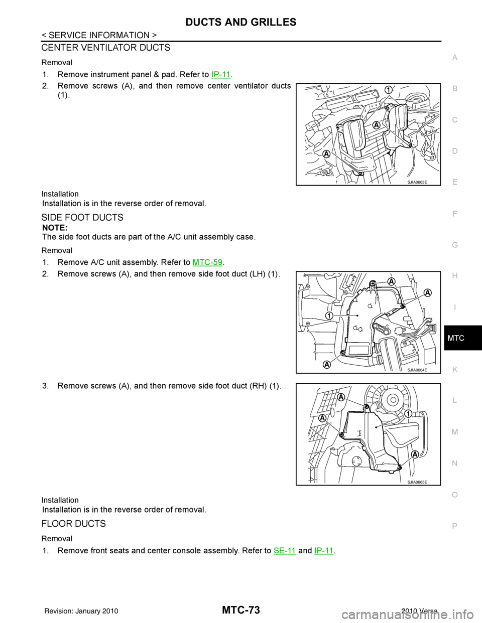
CENTER VENTILATOR DUCTS
Removal
1. Remove instrument panel & pad. Refer to IP-11.
2. Remove screws (A), and then remove center ventilator ducts (1).
Installation
Installation is in the reverse order of removal.
SIDE FOOT DUCTS
NOTE:
The side foot ducts are part of the A/C unit assembly case.
Removal
1. Remove A/C unit assembly. Refer to MTC-59.
2. Remove screws (A), and then remove side foot duct (LH) (1).
3. Remove screws (A), and then remove side foot duct (RH) (1).
Installation
Installation is in the reverse order of removal.
FLOOR DUCTS
Removal
1. Remove front seats and center console assembly. Refer to SE-11 and IP-11.
SJIA0663E
SJIA0664E
SJIA0665E
Revision: January 20102010 Versa
Page 3381 of 3745

PB-6
< SERVICE INFORMATION >
PARKING BRAKE CONTROL
Component
INFOID:0000000005397017
Removal and InstallationINFOID:0000000005397018
REMOVAL
1. Remove center console assembly. Refer to IP-12, "Removal and Installation".
2. Disconnect parking brake switch connector.
3. Loosen adjusting nut.
4. Remove equalizer from rear cable terminal ends.
5. Take off rear cable clip, and unplug rear cable outward. NOTE:
Close opening to take off clip.
6. Remove device assembly nuts, and remove device assembly.
7. Remove rear brake shoe and remove rear cable from the operating lever. Refer to BR-36, "
Removal and
Installation of Drum Brake Assembly".
8. Remove the exhaust center tube and heat plate. Refer to EX-11, "
Removal and Installation".
9. Remove rear cable bolt and nut, and then remove rear cable.
1. Device assembly 2. Adjusting nut3. Parking brake switch
4. Front cable 5. Equalizer6. LH rear cable
7. RH rear cable
AWFIA0531GB
WFIA0510E
Revision: January 20102010 Versa
Page 3491 of 3745

SQUEAK AND RATTLE TROUBLE DIAGNOSESRF-7
< SYMPTOM DIAGNOSIS >
C
DE
F
G H
J
K L
M A
B
RF
N
O P
The following materials, not available through NISSAN Parts Department, can also be used to repair squeaks
and rattles.
UHMW(TEFLON) TAPE
Insulates where slight movement is present. Ideal for instrument panel applications.
SILICONE GREASE
Used in place of UHMW tape that will be visible or not fit.
Note: Will only last a few months.
SILICONE SPRAY
Use when grease cannot be applied.
DUCT TAPE
Use to eliminate movement.
CONFIRM THE REPAIR
Confirm that the cause of a noise is repaired by test driving the vehicle. Operate the vehicle under the same
conditions as when the noise originally occurred. Refer to the notes on the Diagnostic Worksheet.
Generic Squeak and Rattle TroubleshootingINFOID:0000000005396792
Refer to Table of Contents for specific component removal and installation information.
INSTRUMENT PANEL
Most incidents are caused by contact and movement between:
1. The cluster lid A and instrument panel
2. Acrylic lens and combination meter housing
3. Instrument panel to front pillar garnish
4. Instrument panel to windshield
5. Instrument panel pins
6. Wiring harnesses behind the combination meter
7. A/C defroster duct and duct joint
These incidents can usually be located by tapping or moving the components to duplicate the noise or by
pressing on the components while driving to stop the noi se. Most of these incidents can be repaired by apply-
ing felt cloth tape or silicone spray (in hard to reach areas). Urethane pads can be used to insulate wiring har-
ness.
CAUTION:
Do not use silicone spray to isolate a squeak or ra ttle. If you saturate the area with silicone, you will
not be able to recheck the repair.
CENTER CONSOLE
Components to pay attention to include:
1. Shifter assembly cover to finisher
2. A/C control unit and cluster lid C
3. Wiring harnesses behind audio and A/C control unit
The instrument panel repair and isolation pr ocedures also apply to the center console.
DOORS
Pay attention to the:
1. Finisher and inner panel making a slapping noise
2. Inside handle escutcheon to door finisher
3. Wiring harnesses tapping
4. Door striker out of alignment causing a popping noise on starts and stops
Tapping or moving the components or pressing on them while driving to duplicate the conditions can isolate
many of these incidents. You can usually insulate the ar eas with felt cloth tape or insulator foam blocks from
the NISSAN Squeak and Rattle Kit (J-43980) to repair the noise.
TRUNK
Trunk noises are often caused by a loose jack or loose items put into the trunk by the owner.
In addition look for:
1. Trunk lid bumpers out of adjustment
Revision: January 20102010 Versa
Page 3573 of 3745

SQUEAK AND RATTLE TROUBLE DIAGNOSESSE-7
< SERVICE INFORMATION >
C
DE
F
G H
J
K L
M A
B
SE
N
O P
SILICONE GREASE
Used instead of UHMW tape that will be visible or not fit.
Note: Will only last a few months.
SILICONE SPRAY
Use when grease cannot be applied.
DUCT TAPE
Use to eliminate movement.
CONFIRM THE REPAIR
Confirm that the cause of a noise is repaired by test driving the vehicle. Operate the vehicle under the same
conditions as when the noise originally occurred. Refer to the notes on the Diagnostic Worksheet.
Generic Squeak and Rattle TroubleshootingINFOID:0000000005396866
Refer to Table of Contents for specific component removal and installation information.
INSTRUMENT PANEL
Most incidents are caused by contact and movement between:
1. The cluster lid A and instrument panel
2. Acrylic lens and combination meter housing
3. Instrument panel to front pillar garnish
4. Instrument panel to windshield
5. Instrument panel mounting pins
6. Wiring harnesses behind the combination meter
7. A/C defroster duct and duct joint
These incidents can usually be located by tapping or moving the components to duplicate the noise or by
pressing on the components while driving to stop the noi se. Most of these incidents can be repaired by apply-
ing felt cloth tape or silicone spray (in hard to reach areas). Urethane pads can be used to insulate wiring har-
ness.
CAUTION:
Do not use silicone spray to isolate a squeak or ra ttle. If you saturate the area with silicone, you will
not be able to recheck the repair.
CENTER CONSOLE
Components to pay attention to include:
1. Shifter assembly cover to finisher
2. A/C control unit and cluster lid C
3. Wiring harnesses behind audio and A/C control unit
The instrument panel repair and isolation pr ocedures also apply to the center console.
DOORS
Pay attention to the:
1. Finisher and inner panel making a slapping noise
2. Inside handle escutcheon to door finisher
3. Wiring harnesses tapping
4. Door striker out of alignment causing a popping noise on starts and stops
Tapping or moving the components or pressing on them while driving to duplicate the conditions can isolate
many of these incidents. You can usually insulate the ar eas with felt cloth tape or insulator foam blocks from
the NISSAN Squeak and Rattle Kit (J-43980) to repair the noise.
TRUNK
Trunk noises are often caused by a loose jack or loose items put into the trunk by the owner.
In addition look for:
1. Trunk lid bumpers out of adjustment
2. Trunk lid striker out of adjustment
3. The trunk lid torsion bars knocking together
4. A loose license plate or bracket
Revision: January 20102010 Versa
Page 3638 of 3745
DIAGNOSIS SENSOR UNITSRS-45
< ON-VEHICLE REPAIR >
C
DE
F
G
I
J
K L
M A
B
SRS
N
O P
DIAGNOSIS SENSOR UNIT
Removal and InstallationINFOID:0000000005396922
REMOVAL
WARNING:
Before disconnecting diagnosis sensor unit harness connector(s), be sure to disconnect harness con-
nectors from air bag modules and front seat belt pre-tensioner to prevent deployment by static elec-
tricity.
CAUTION:
• Before servicing the SRS, turn th e ignition switch OFF, disconnect both battery terminals and wait at
least three minutes.
• Do not disassemble diagnosis sensor unit.
• Do not use old bolts; replace with new bolts.
• Replace the diagnosis sensor unit if it has been dropped or sustained an impact.
• Check diagnosis sensor unit bracket to make sure it is free of deformities, dents, cracks or rust. If it
shows any visible signs of da mage, replace with new one.
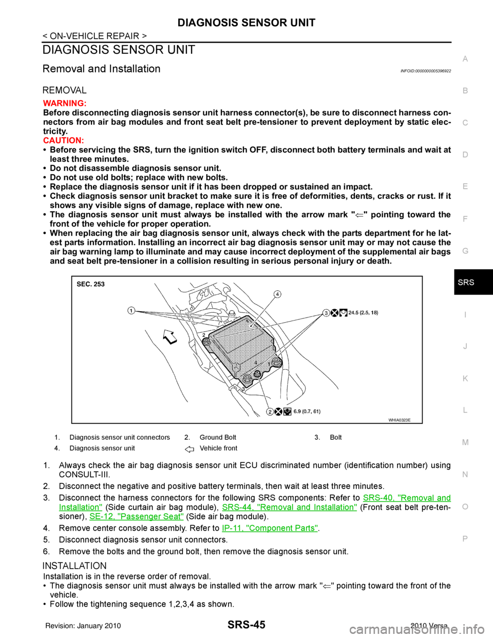
• The diagnosis sensor unit must always be installed with the arrow mark " ⇐" pointing toward the
front of the vehicle for proper operation.
• When replacing the air bag diagno sis sensor unit, always check with the parts department for he lat-
est parts information. Installing an incorrect air bag diagnosis sensor unit may or may not cause the
air bag warning lamp to illuminate and may cause incorrect deployment of the supplemental air bags
and seat belt pre-tensioner in a collision r esulting in serious personal injury or death.
1. Always check the air bag diagnosis sensor unit E CU discriminated number (identification number) using
CONSULT-III.
2. Disconnect the negative and positive battery term inals, then wait at least three minutes.
3. Disconnect the harness connectors for the following SRS components: Refer to SRS-40, "
Removal and
Installation" (Side curtain air bag module), SRS-44, "Removal and Installation" (Front seat belt pre-ten-
sioner), SE-12, "
Passenger Seat" (Side air bag module).
4. Remove center console assembly. Refer to IP-11, "
Component Parts".
5. Disconnect diagnosis sensor unit connectors.
6. Remove the bolts and the ground bolt, then remove the diagnosis sensor unit.
INSTALLATION
Installation is in the reverse order of removal.
• The diagnosis sensor unit must always be installed with the arrow mark " ⇐" pointing toward the front of the
vehicle.
• Follow the tightening sequence 1,2,3,4 as shown.
1. Diagnosis sensor unit connectors 2. Ground Bolt 3. Bolt
4. Diagnosis sensor unit Vehicle front
WHIA0323E
Revision: January 20102010 Versa