wheel torque NISSAN TIIDA 2010 Service Owner's Guide
[x] Cancel search | Manufacturer: NISSAN, Model Year: 2010, Model line: TIIDA, Model: NISSAN TIIDA 2010Pages: 3745, PDF Size: 73.67 MB
Page 3463 of 3745
NOISE, VIBRATION AND HARSHNESS (NVH) TROUBLESHOOTINGPS-5
< SERVICE INFORMATION >
C
DE
F
H I
J
K L
M A
B
PS
N
O P
NOISE, VIBRATION AND HARSHN ESS (NVH) TROUBLESHOOTING
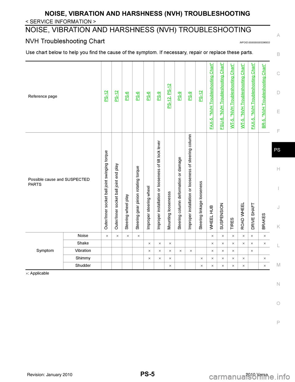
NVH Troubleshooting ChartINFOID:0000000005396933
Use chart below to help you find the cause of the symptom. If necessary, repair or replace these parts.
×: ApplicableReference page
PS-12PS-12PS-6PS-6PS-6PS-9
PS-12
,
PS-12PS-9PS-9PS-12
FAX-5, "
NVH Troubleshooting Chart
"
FSU-6, "
NVH Troubleshooting Chart
"
WT-5, "
NVH Troubleshooting Chart
"
WT-5, "
NVH Troubleshooting Chart
"
FAX-5, "
NVH Troubleshooting Chart
"
BR-5, "
NVH Troubleshooting Chart
"
Possible cause and SUSPECTED
PA R T S
Outer/Inner socket ball joint swinging torque
Outer/Inner socket ball joint end play
Steering wheel play
Steering gear pinion rotating torque
Improper steering wheel
Improper installation or looseness of tilt lock lever
Mounting loosenesss
Steering column deformation or damage
Improper installation or looseness of steering column
Steering linkage looseness
WHEEL HUB
SUSPENSION
TIRES
ROAD WHEEL
DRIVE SHAFT
BRAKES
Symptom Noise
××× × ××××× ×
Shake ×××××××× ×
Vibration ××××× ××× ×
Shimmy ×××× ×××× ×
Shudder ×× ×××× ×
Revision: January 20102010 Versa
Page 3468 of 3745
PS-10
< SERVICE INFORMATION >
STEERING COLUMN
6. Remove steering column assembly mounting nuts, and then remove steering column assembly from vehi-cle.
7. Remove bolt of intermediate shaft (lower side), and then remove intermediate shaft from vehicle.
8. Remove screws of bracket and EPS control unit, and then remove bracket and EPS control unit from steering column assembly.
INSPECTION AFTER REMOVAL
• Check each part of steering column assembly, EPS control unit and intermediate shaft for damage and.replace as necessary.
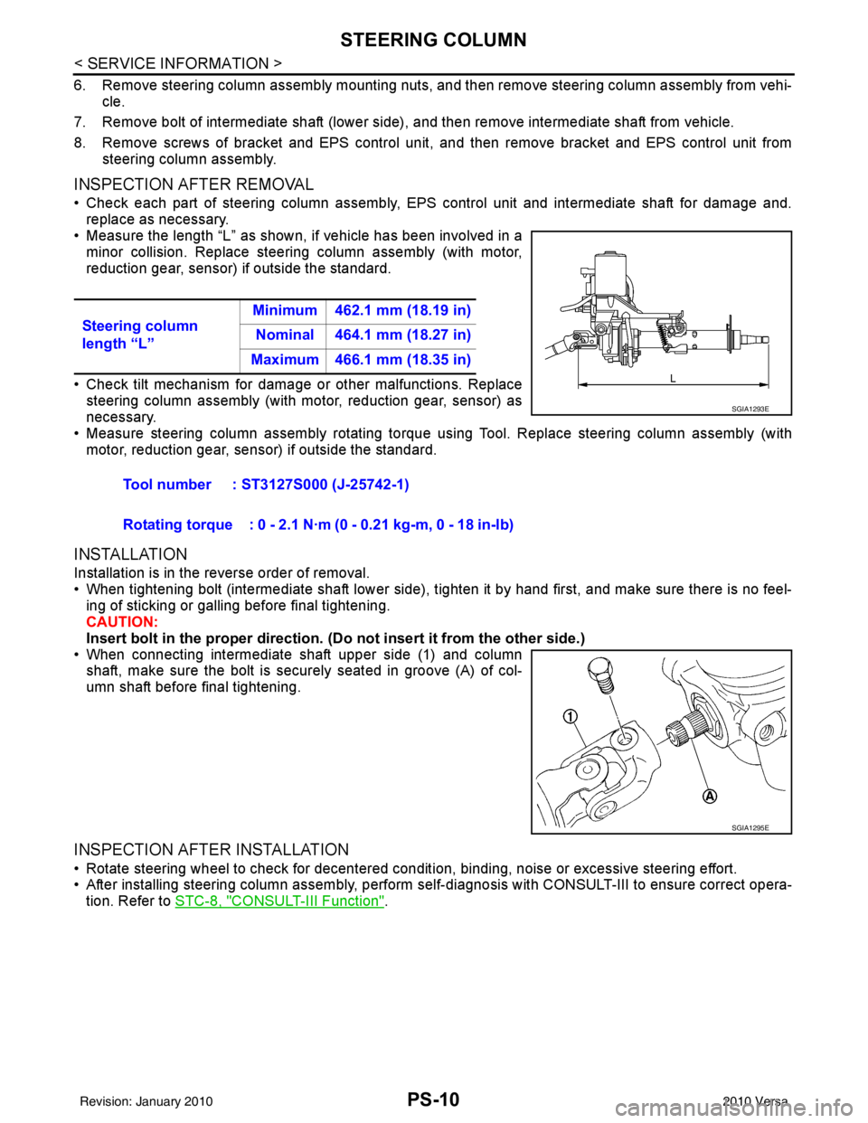
• Measure the length “L” as shown, if vehicle has been involved in a minor collision. Replace steering column assembly (with motor,
reduction gear, sensor) if outside the standard.
• Check tilt mechanism for damage or other malfunctions. Replace
steering column assembly (with motor, reduction gear, sensor) as
necessary.
• Measure steering column assembly rotating torque using Tool. Replace steering column assembly (with motor, reduction gear, sensor) if outside the standard.
INSTALLATION
Installation is in the reverse order of removal.
• When tightening bolt (intermediate shaft lower side), tighten it by hand first, and make sure there is no feel-
ing of sticking or galling before final tightening.
CAUTION:
Insert bolt in the proper direction. (Do not insert it from the other side.)
• When connecting intermediate shaft upper side (1) and column shaft, make sure the bolt is securely seated in groove (A) of col-
umn shaft before final tightening.
INSPECTION AFTER INSTALLATION
• Rotate steering wheel to check for decentered conditi on, binding, noise or excessive steering effort.
• After installing steering column assembly, perform self-diagnosis with CONSULT-III to ensure correct opera-
tion. Refer to STC-8, "
CONSULT-III Function".
Steering column
length “L”
Minimum 462.1 mm (18.19 in)
Nominal 464.1 mm (18.27 in)
Maximum 466.1 mm (18.35 in)
Tool number : ST3127S000 (J-25742-1)
Rotating torque : 0 - 2.1 N·m (0 - 0.21 kg-m, 0 - 18 in-lb)
SGIA1293E
SGIA1295E
Revision: January 20102010 Versa
Page 3473 of 3745
POWER STEERING GEARPS-15
< SERVICE INFORMATION >
C
DE
F
H I
J
K L
M A
B
PS
N
O P
1. Apply recommended grease to teeth part and bush part of rack assembly, if necessary.
2. Apply recommended grease to back of rack assembly, if necessary.
3. Install inner socket to rack assembly. Torque to specified value while holding the flat portion of the rack next to the inner socket using a suitable tool.
4. Apply recommended grease to inner socket.
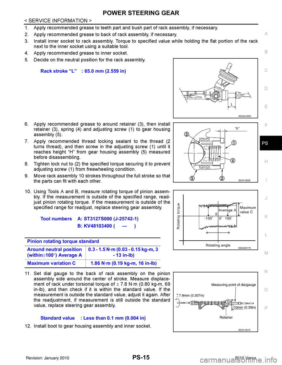
5. Decide on the neutral position for the rack assembly.
6. Apply recommended grease to around retainer (3), then install retainer (3), spring (4) and adjusting screw (1) to gear housing
assembly (5).
7. Apply recommended thread locking sealant to the thread (2 turns thread), and then screw in the adjusting screw (1) until it
reaches height “H” from gear housing assembly (5) measured
before disassembling.
8. Tighten lock nut to (2) the specified torque securing it to prevent adjusting screw (1) from freewheeling condition.
9. Move rack assembly 10 strokes throughout the full stroke so that the parts can fit with each other.
10. Using Tools A and B, measure rotating torque of pinion assem- bly. If the measurement is outside of the specified range, read-
just pinion rotating torque. If the measurement is outside of the
specified range for readjust, replace steering gear assembly.
11. Set dial gauge to the back of rack assembly on the pinion assembly side around the center of stroke. Measure displace-
ment of rack under torsional torque of ± 7.8 N·m (0.80 kg-m, 69
in-lb), and then check if it is within the standard value. If the
measurement is outside the standard value, adjust it again. After
the readjustment, if measurement is still outside the standard
value, replace steering gear assembly.
12. Install boot to gear housing assembly and inner socket. Rack stroke “L” : 65.0 mm (2.559 in)
WGIA0185E
SGIA1300E
Tool numbers A: ST3127S000 (J-25742-1)
B: KV48103400 ( — )
Pinion rotating torque standard
Around neutral position
(within ±100° ) Average A 0.3 - 1.5 N·m (0.03 - 0.15 kg-m, 3
- 13 in-lb)
Maximum variation C 1.86 N·m (0.19 kg-m, 16 in-lb)
MGIA0017E
Standard value : Less than 0.1 mm (0.004 in)
SGIA1301E
Revision: January 20102010 Versa
Page 3474 of 3745
PS-16
< SERVICE INFORMATION >
POWER STEERING GEAR
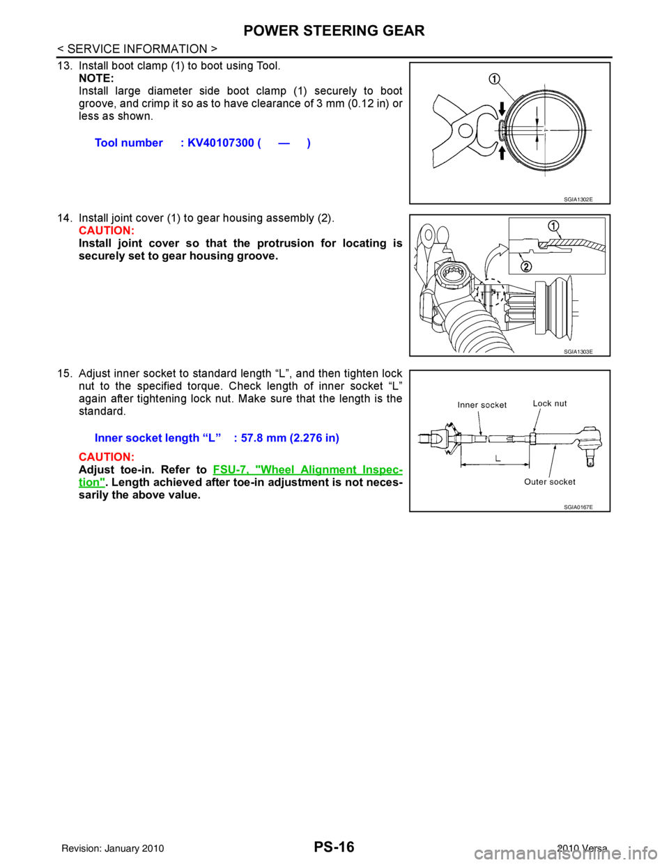
13. Install boot clamp (1) to boot using Tool.NOTE:
Install large diameter side boot clamp (1) securely to boot
groove, and crimp it so as to have clearance of 3 mm (0.12 in) or
less as shown.
14. Install joint cover (1) to gear housing assembly (2). CAUTION:
Install joint cover so that the protrusion for locating is
securely set to gear housing groove.
15. Adjust inner socket to standard length “L”, and then tighten lock nut to the specified torque. Check length of inner socket “L”
again after tightening lock nut. Make sure that the length is the
standard.
CAUTION:
Adjust toe-in. Refer to FSU-7, "
Wheel Alignment Inspec-
tion". Length achieved after toe-in adjustment is not neces-
sarily the above value. Tool number : KV40107300 ( — )
SGIA1302E
SGIA1303E
Inner socket length “L” : 57.8 mm (2.276 in)
SGIA0167E
Revision: January 20102010 Versa
Page 3475 of 3745
SERVICE DATA AND SPECIFICATIONS (SDS)PS-17
< SERVICE INFORMATION >
C
DE
F
H I
J
K L
M A
B
PS
N
O P
SERVICE DATA AND SPECIFICATIONS (SDS)
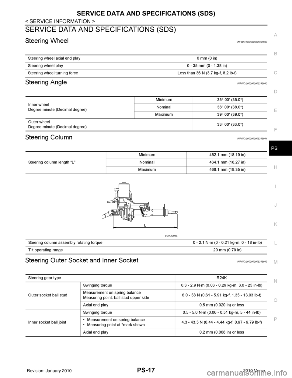
Steering WheelINFOID:0000000005396939
Steering AngleINFOID:0000000005396940
Steering ColumnINFOID:0000000005396941
Steering Outer Socket and Inner SocketINFOID:0000000005396942
Steering wheel axial end play 0 mm (0 in)
Steering wheel play 0 - 35 mm (0 - 1.38 in)
Steering wheel turning force Less than 36 N (3.7 kg-f, 8.2 lb-f)
Inner wheel
Degree minute (Decimal degree)Minimum
35° 00 ′ (35.0 °)
Nominal 38° 00 ′ (38.0 °)
Maximum 39° 00 ′ (39.0 °)
Outer wheel
Degree minute (Decimal degree) 33
° 00 ′ (33.0 °)
Steering column length “L” Minimum
462.1 mm (18.19 in)
Nominal 464.1 mm (18.27 in)
Maximum 466.1 mm (18.35 in)
Steering column assembly rotating torque 0 - 2.1 N·m (0 - 0.21 kg-m, 0 - 18 in-lb)
Tilt operating range 20 mm (0.79 in)
SGIA1293E
Steering gear type R24K
Outer socket ball stud Swinging torque
0.3 - 2.9 N·m (0.03 - 0.29 kg-m, 3.0 - 25 in-lb)
Measurement on spring balance
Measuring point: ball stud upper side 6.0 - 58 N (0.61 - 5.91 kg-f, 1.35 - 13.03 lb-f)
Axial end play 0.5 mm (0.020 in) or less
Inner socket ball joint Swinging torque
0.5 - 5.0 N·m (0.06 - 0.51 kg-m, 5 - 44 in-lb)
• Measurement on spring balance
• Measuring point at *mark shown 4.3 - 43.5 N (0.44 - 4.44 kg-f, 0.97 - 9.79 lb-f)
Axial end play 0.2 mm (0.008 in) or less
Revision: January 20102010 Versa
Page 3523 of 3745
SHOCK ABSORBERRSU-9
< SERVICE INFORMATION >
C
DF
G H
I
J
K L
M A
B
RSU
N
O P
SHOCK ABSORBER
Removal and InstallationINFOID:0000000005397080
REMOVAL
1. Remove wheel and tire using power tool.
2. Remove wheel sensor from wheel hub and bearing assembly and rear suspension beam. Refer to BRC-
34 .
CAUTION:
Do not pull on wheel sensor harness.
3. Remove shock absorber mask from trunk side fini sher using a flat-bladed screwdriver. Refer to EI-54
.
CAUTION:
Wrap the tip of a screwdriver with cl oth to avoid damaging components.
4. Set jack under rear suspension beam.
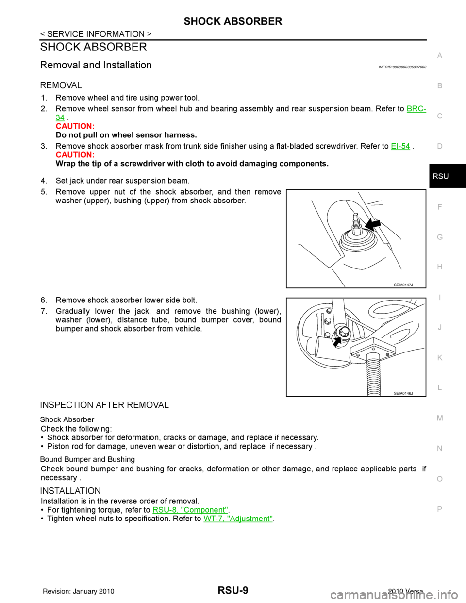
5. Remove upper nut of the shock absorber, and then remove washer (upper), bushing (upper) from shock absorber.
6. Remove shock absorber lower side bolt.
7. Gradually lower the jack, and remove the bushing (lower), washer (lower), distance tube, bound bumper cover, bound
bumper and shock absorber from vehicle.
INSPECTION AFTER REMOVAL
Shock Absorber
Check the following:
• Shock absorber for deformation, cracks or damage, and replace if necessary.
• Piston rod for damage, uneven wear or distortion, and replace if necessary .
Bound Bumper and Bushing
Check bound bumper and bushing for cracks, deformation or other damage, and replace applicable parts if
necessary .
INSTALLATION
Installation is in the reverse order of removal.
• For tightening torque, refer to RSU-8, "
Component".
• Tighten wheel nuts to specification. Refer to WT-7, "
Adjustment".
SEIA0147J
SEIA0146J
Revision: January 20102010 Versa
Page 3525 of 3745
COIL SPRINGRSU-11
< SERVICE INFORMATION >
C
DF
G H
I
J
K L
M A
B
RSU
N
O P
COIL SPRING
Removal and InstallationINFOID:0000000005397081
REMOVAL
1. Remove wheel and tire using power tool.
2. Remove wheel sensor from wheel hub and bearing assembly. Refer to BRC-34, "
Removal and Installa-
tion".
CAUTION:
Do not pull on wheel sensor harness.
3. Set jack under rear suspension beam.
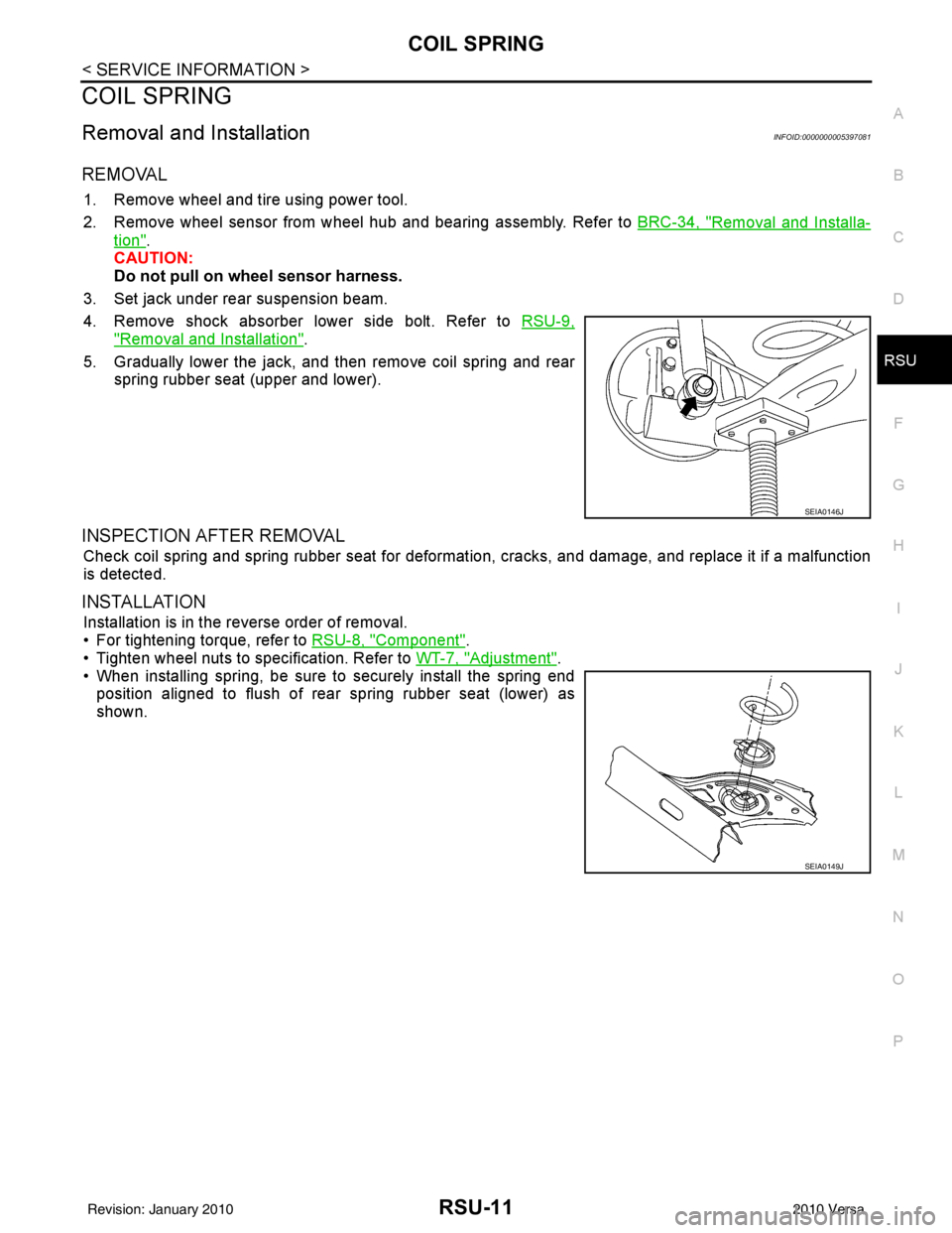
4. Remove shock absorber lower side bolt. Refer to RSU-9,
"Removal and Installation".
5. Gradually lower the jack, and then remove coil spring and rear spring rubber seat (upper and lower).
INSPECTION AFTER REMOVAL
Check coil spring and spring rubber seat for deformation, cracks, and damage, and replace it if a malfunction
is detected.
INSTALLATION
Installation is in the reverse order of removal.
• For tightening torque, refer to RSU-8, "
Component".
• Tighten wheel nuts to specification. Refer to WT-7, "
Adjustment".
• When installing spring, be sure to securely install the spring end position aligned to flush of rear spring rubber seat (lower) as
shown.
SEIA0146J
SEIA0149J
Revision: January 20102010 Versa
Page 3526 of 3745
RSU-12
< SERVICE INFORMATION >
REAR SUSPENSION BEAM
REAR SUSPENSION BEAM
Removal and InstallationINFOID:0000000005397082
REMOVAL
1. Remove wheel and tire using power tool.
2. Separate parking brake rear cable from rear drum brake and rear suspension beam. Refer to PB-5, "
On-
Vehicle Service".
3. Remove wheel sensor and wheel sensor harness from wheel hub and bearing assembly and rear suspen-
sion beam. Refer to BRC-34, "
Removal and Installation".
4. Remove lock plate and separate brake tube from brake hose. Refer to BR-12, "
Rear Brake Tube and Hose".
5. Remove wheel hub and bearing assembly and back plate. Refer to RAX-6, "
On-Vehicle Inspection and Service".
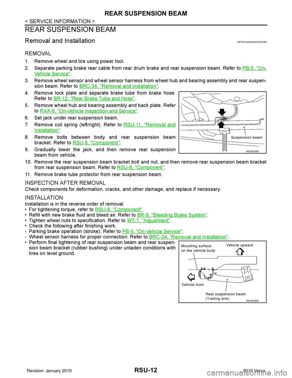
6. Set jack under rear suspension beam.
7. Remove coil spring (left/right). Refer to RSU-11, "
Removal and
Installation".
8. Remove bolts between body and rear suspension beam bracket. Refer to RSU-8, "
Component".
9. Gradually lower the jack, and then remove rear suspension beam from vehicle.
10. Remove the rear suspension beam bracket bolt and nut, and then remove rear suspension beam bracket
from rear suspension beam. Refer to RSU-8, "
Component".
11. Remove brake tube protector from rear suspension beam.
INSPECTION AFTER REMOVAL
Check components for deformation, cracks, and other damage, and replace if necessary.
INSTALLATION
Installation is in the reverse order of removal.
• For tightening torque, refer to RSU-8, "
Component".
• Refill with new brake fluid and bleed air. Refer to BR-9, "
Bleeding Brake System".
• Tighten wheel nuts to specification. Refer to WT-7, "
Adjustment".
• Check the following after finishing work.
- Parking brake operation (stroke): Refer to PB-5, "
On-Vehicle Service".
- Wheel sensor harness for proper connection: Refer to BRC-34, "
Removal and Installation".
• Perform final tightening of rear suspension beam and rear suspen-
sion beam bracket (rubber bushing) under unladen conditions with
tires on level ground.
MEIA0029E
MEIA0030E
Revision: January 20102010 Versa
Page 3647 of 3745

STC-1
STEERING
C
DE
F
H I
J
K L
M
SECTION STC
A
B
STC
N
O P
CONTENTS
STEERING CONTROL SYSTEM
EPS
BASIC INSPECTION ....... .............................
3
DIAGNOSIS AND REPAIR WORKFLOW ..... .....3
Work Flow ........................................................... ......3
SYSTEM DESCRIPTION ..............................5
EPS SYSTEM ... .............................................. .....5
System Diagram .................................................. ......5
System Description ...................................................5
Component Parts Location ........................................6
Component Description .............................................6
DIAGNOSIS SYSTEM (EPS CONTROL UNIT)
.....
8
CONSULT-III Function ........................................ ......8
DTC/CIRCUIT DIAGNOSIS ..........................9
C1601 BATTERY POWER SUPPLY ..................9
Description .......................................................... ......9
DTC Logic .................................................................9
Diagnosis Procedure .................................................9
C1604 TORQUE SENSOR .................................11
Description ..............................................................11
DTC Logic ...............................................................11
Diagnosis Procedure ...............................................11
C1606 EPS MOTOR ...........................................13
Description .......................................................... ....13
DTC Logic ...............................................................13
Diagnosis Procedure ...............................................13
Component Inspection ............................................13
C1607, C1608 EPS CONTROL UNIT ................15
Description .......................................................... ....15
DTC Logic ...............................................................15
Diagnosis Procedure ...............................................15
C1609 VEHICLE SPEED SIGNAL .....................16
Description ........................................................... ....16
DTC Logic ................................................................16
Diagnosis Procedure ...............................................16
C1610 ENGINE STATUS SIGNAL ...................17
Description ...............................................................17
DTC Logic ................................................................17
Diagnosis Procedure ...............................................17
U1000 CAN COMM CIRCUIT ...........................18
Description ...............................................................18
DTC Logic ................................................................18
Diagnosis Procedure ...............................................18
EPS WARNING LAMP ......................................19
Description ...............................................................19
Component Function Check ....................................19
Diagnosis Procedure ...............................................19
ECU DIAGNOSIS INFORMATION ..............20
EPS CONTROL UNIT .......................................20
Reference Value .................................................. ....20
Wiring Diagram - ELECTRONICALLY CON-
TROLLED POWER STEERING SYSTEM - ............
22
Fail-Safe .............................................................. ....23
DTC Inspection Priority Chart ..................................24
DTC Index ...............................................................24
SYMPTOM DIAGNOSIS ..............................25
EPS WARNING LAMP DOES NOT TURN ON ...25
Description ........................................................... ....25
Diagnosis Procedure ...............................................25
EPS WARNING LAMP DOES NOT TURN
OFF ....................................................................
26
Description ...............................................................26
Diagnosis Procedure ...............................................26
STEERING WHEEL TURNING FORCE IS
HEAVY OR LIGHT ............................................
27
Revision: January 20102010 Versa
Page 3648 of 3745

STC-2
Description ..............................................................27
Diagnosis Procedure ..............................................27
UNBALANCE STEERING WHEEL TURNING
FORCE AND RETURN BETWEEN RIGHT
AND LEFT ..........................................................
28
Description ..............................................................28
Diagnosis Procedure ..............................................28
UNBALANCE STEERING WHEEL TURNING
FORCE (TORQUE VARIATION) .......................
29
Description ........................................................... ...29
Diagnosis Procedure ............................................ ...29
PRECAUTION ............................................30
PRECAUTIONS .............................................. ...30
Precaution for Supplemental Restraint System
(SRS) "AIR BAG" and "SEAT BELT PRE-TEN-
SIONER" .............................................................. ...
30
Precaution Necessary for Steering Wheel Rota-
tion After Battery Disconnect ..................................
30
Service Notice or Precaution for EPS System ........31
Revision: January 20102010 Versa