Coolant sensor NISSAN TIIDA 2010 Service Manual PDF
[x] Cancel search | Manufacturer: NISSAN, Model Year: 2010, Model line: TIIDA, Model: NISSAN TIIDA 2010Pages: 3745, PDF Size: 73.67 MB
Page 1749 of 3745
EC-484
< SYMPTOM DIAGNOSIS >[HR16DE]
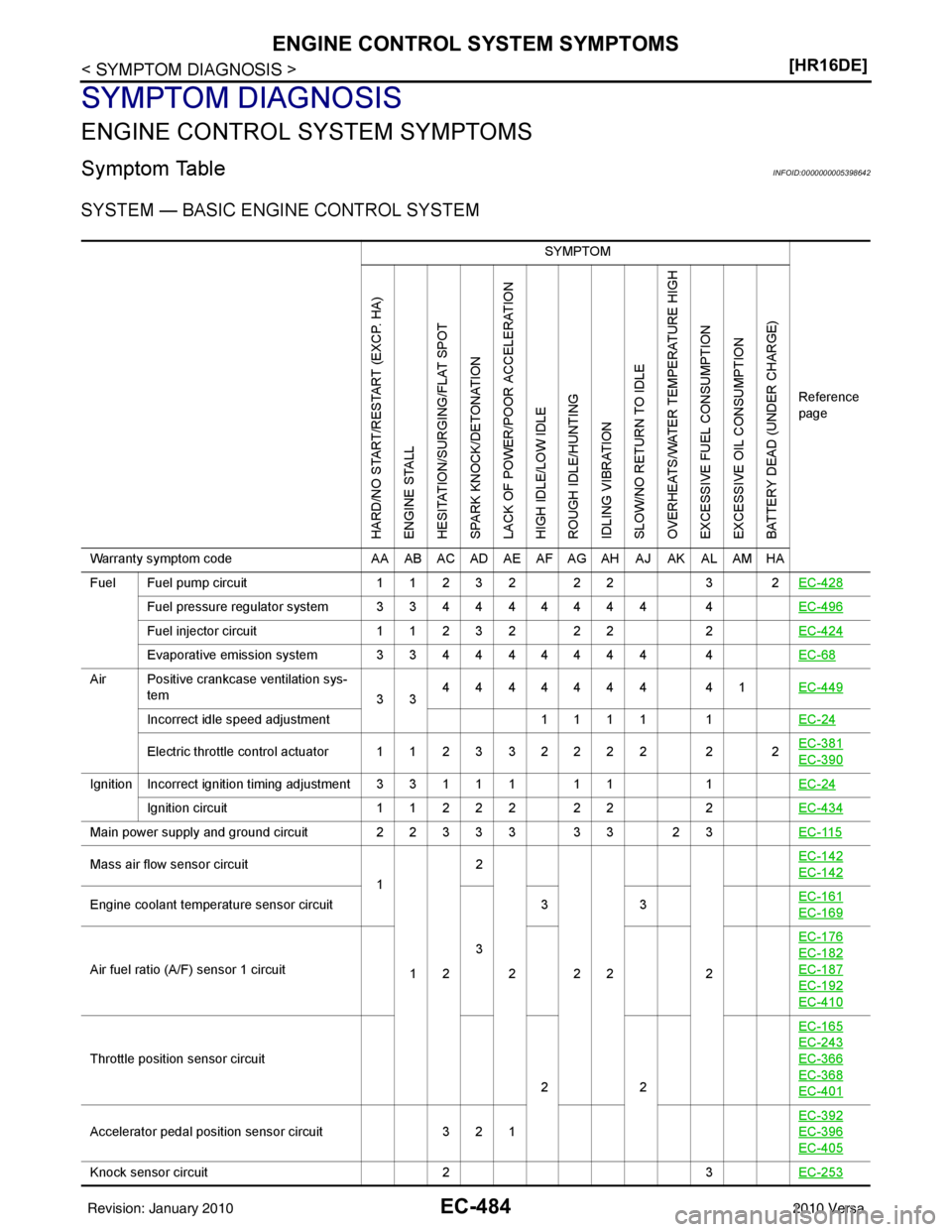
ENGINE CONTROL SYSTEM SYMPTOMS
SYMPTOM DIAGNOSIS
ENGINE CONTROL SYSTEM SYMPTOMS
Symptom TableINFOID:0000000005398642
SYSTEM — BASIC ENGINE CONTROL SYSTEM
SYMPTOM
Reference
page
HARD/NO START/RESTART (EXCP. HA)
ENGINE STALL
HESITATION/SURGING/FLAT SPOT
SPARK KNOCK/DETONATION
LACK OF POWER/POOR ACCELERATION
HIGH IDLE/LOW IDLE
ROUGH IDLE/HUNTING
IDLING VIBRATION
SLOW/NO RETURN TO IDLE
OVERHEATS/WATER TEMPERATURE HIGH
EXCESSIVE FUEL CONSUMPTION
EXCESSIVE OIL CONSUMPTION
BATTERY DEAD (UNDER CHARGE)
Warranty symptom code AA AB AC AD AE AF AG AH AJ AK AL AM HA
Fuel Fuel pump circuit 11232 22 3 2EC-428
Fuel pressure regulator system 334444444 4 EC-496
Fuel injector circuit11232 22 2EC-424
Evaporative emission system 334444444 4 EC-68
Air Positive crankcase ventilation sys-
tem 334444444 41
EC-449
Incorrect idle speed adjustment 1 1 1 1 1EC-24
Electric throttle control actuator 112332222 2 2 EC-381EC-390
IgnitionIncorrect ignition timing adjustment33111 11
1EC-24
Ignition circuit 11222 22 2EC-434
Main power supply and ground circuit 22333 33 23 EC-115
Mass air flow sensor circuit
1
12 2
222 2 EC-142EC-142
Engine coolant temperature sensor circuit
333
EC-161EC-169
Air fuel ratio (A/F) sensor 1 circuit EC-176
EC-182
EC-187
EC-192
EC-410
Throttle position sensor circuit
22EC-165
EC-243
EC-366
EC-368
EC-401
Accelerator pedal position sensor circuit
3 2 1 EC-392EC-396
EC-405
Knock sensor circuit
23EC-253
Revision: January 20102010 Versa
Page 1760 of 3745
PREPARATIONEC-495
< PREPARATION > [HR16DE]
C
D
E
F
G H
I
J
K L
M A
EC
NP
O
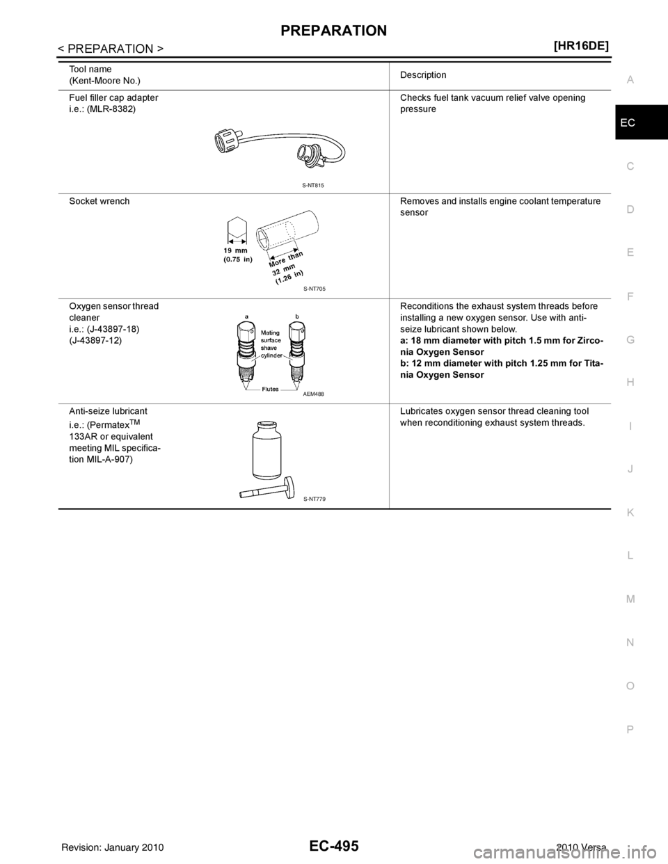
Fuel filler cap adapter
i.e.: (MLR-8382)
Checks fuel tank vacuum relief valve opening
pressure
Socket wrench Removes and installs engine coolant temperature
sensor
Oxygen sensor thread
cleaner
i.e.: (J-43897-18)
(J-43897-12) Reconditions the exhaust system threads before
installing a new oxygen sensor. Use with anti-
seize lubricant shown below.
a: 18 mm diameter with pitch 1.5 mm for Zirco-
nia Oxygen Sensor
b: 12 mm diameter with pitch 1.25 mm for Tita-
nia Oxygen Sensor
Anti-seize lubricant
i.e.: (Permatex
TM
133AR or equivalent
meeting MIL specifica-
tion MIL-A-907) Lubricates oxygen sensor thread cleaning tool
when reconditioning exhaust system threads.
Tool name
(Kent-Moore No.)
Description
S-NT815
S-NT705
AEM488
S-NT779
Revision: January 20102010 Versa
Page 1780 of 3745
PREPARATIONEC-515
< SERVICE INFORMATION > [MR18DE]
C
D
E
F
G H
I
J
K L
M A
EC
NP
O
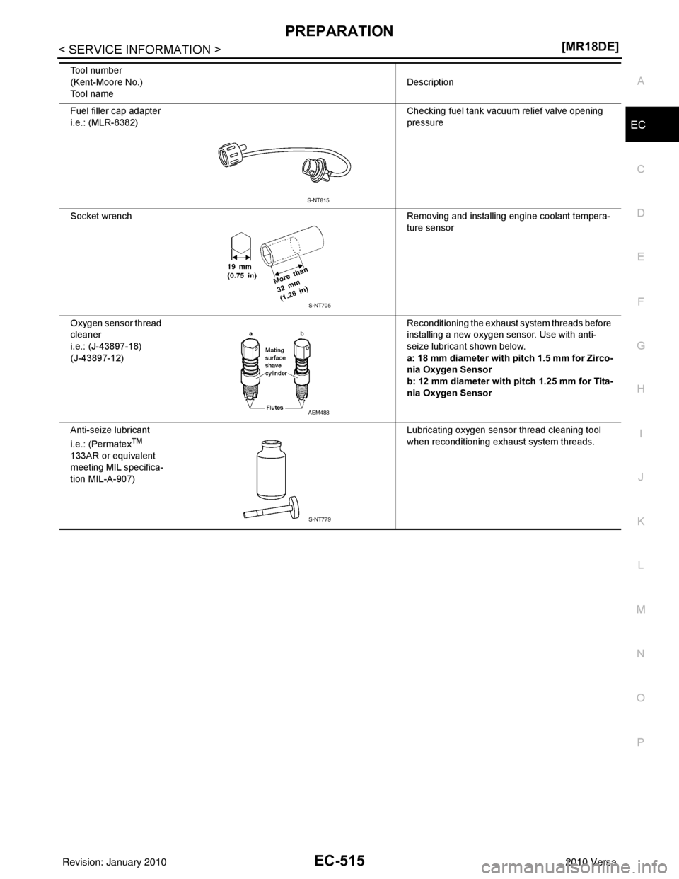
Fuel filler cap adapter
i.e.: (MLR-8382)
Checking fuel tank vacuum relief valve opening
pressure
Socket wrench Removing and installing engine coolant tempera-
ture sensor
Oxygen sensor thread
cleaner
i.e.: (J-43897-18)
(J-43897-12) Reconditioning the exhaust system threads before
installing a new oxygen sensor. Use with anti-
seize lubricant shown below.
a: 18 mm diameter with pitch 1.5 mm for Zirco-
nia Oxygen Sensor
b: 12 mm diameter with pitch 1.25 mm for Tita-
nia Oxygen Sensor
Anti-seize lubricant
i.e.: (Permatex
TM
133AR or equivalent
meeting MIL specifica-
tion MIL-A-907) Lubricating oxygen sensor thread cleaning tool
when reconditioning exhaust system threads.
Tool number
(Kent-Moore No.)
Tool name
Description
S-NT815
S-NT705
AEM488
S-NT779
Revision: January 20102010 Versa
Page 1782 of 3745
ENGINE CONTROL SYSTEMEC-517
< SERVICE INFORMATION > [MR18DE]
C
D
E
F
G H
I
J
K L
M A
EC
NP
O
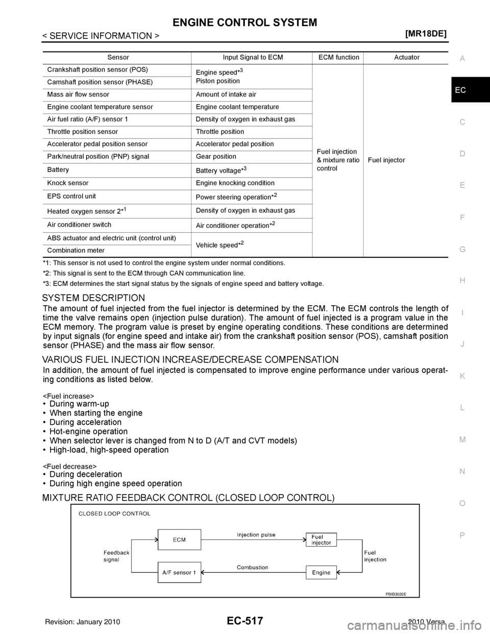
*1: This sensor is not used to control the engine system under normal conditions.
*2: This signal is sent to the ECM through CAN communication line.
*3: ECM determines the start signal status by the signals of engine speed and battery voltage.
SYSTEM DESCRIPTION
The amount of fuel injected from the fuel injector is
determined by the ECM. The ECM controls the length of
time the valve remains open (injection pulse duration). T he amount of fuel injected is a program value in the
ECM memory. The program value is preset by engine operating conditions. These conditions are determined
by input signals (for engine speed and intake air) from t he crankshaft position sensor (POS), camshaft position
sensor (PHASE) and the mass air flow sensor.
VARIOUS FUEL INJECTION INCREASE/DECREASE COMPENSATION
In addition, the amount of fuel injected is compensated to improve engine performance under various operat-
ing conditions as listed below.
• When starting the engine
• During acceleration
• Hot-engine operation
• When selector lever is changed from N to D (A/T and CVT models)
• High-load, high-speed operation
• During high engine speed operation
MIXTURE RATIO FEEDBACK CONTROL (CLOSED LOOP CONTROL)
Sensor Input Signal to ECMECM functionActuator
Crankshaft position sensor (POS) Engine speed*
3
Piston position
Fuel injection
& mixture ratio
controlFuel injector
Camshaft position sensor (PHASE)
Mass air flow sensor
Amount of intake air
Engine coolant temperature sensor Engine coolant temperature
Air fuel ratio (A/F) sensor 1 Density of oxygen in exhaust gas
Throttle position sensor Throttle position
Accelerator pedal position sensor Accelerator pedal position
Park/neutral position (PNP) signal Gear position
Battery Battery voltage*
3
Knock sensor Engine knocking condition
EPS control unit Power steering operation*
2
Heated oxygen sensor 2*1Density of oxygen in exhaust gas
Air conditioner switch Air conditioner operation*
2
ABS actuator and electric unit (control unit)
Vehicle speed*2
Combination meter
PBIB3020E
Revision: January 20102010 Versa
Page 1783 of 3745
EC-518
< SERVICE INFORMATION >[MR18DE]
ENGINE CONTROL SYSTEM
The mixture ratio feedback system provides the best air/fuel mixture ratio for drivability and emission control.
The three way catalyst (manifold) can then better r
educe CO, HC and NOx emissions. This system uses air
fuel ratio (A/F) sensor 1 in the exhaust manifold to monitor whether the engine operation is rich or lean. The
ECM adjusts the injection pulse width according to t he sensor voltage signal. For more information about air
fuel ratio (A/F) sensor 1, refer to EC-704
. This maintains the mixture ratio within the range of stoichiometric
(ideal air/fuel mixture).
This stage is referred to as the closed loop control condition.
Heated oxygen sensor 2 is located downstream of the th ree way catalyst (manifold). Even if the switching
characteristics of air fuel ratio (A/F) sensor 1 shift, the air/fuel ratio is controlled to stoichiometric by the signal
from heated oxygen sensor 2.
Open Loop Control
The open loop system condition refers to when the ECM detects any of the following conditions. Feedback
control stops in order to maintain stabilized fuel combustion.
• Deceleration and acceleration
• High-load, high-speed operation
• Malfunction of air fuel ratio (A/F) sensor 1 or its circuit
• Insufficient activation of air fuel ratio (A /F) sensor 1 at low engine coolant temperature
• High engine coolant temperature
• During warm-up
• After shifting from N to D (A/T and CVT models)
• When starting the engine
MIXTURE RATIO SELF-LEARNING CONTROL
The mixture ratio feedback control system monitors the mixt ure ratio signal transmitted from air fuel ratio (A/F)
sensor 1. This feedback signal is then sent to the ECM. The ECM controls the basic mixture ratio as close to
the theoretical mixture ratio as possible. However, the bas ic mixture ratio is not necessarily controlled as orig-
inally designed. Both manufacturing differences (i.e., mass air flow sensor hot wire) and characteristic
changes during operation (i.e., fuel injector clogging) directly affect mixture ratio.
Accordingly, the difference between the basic and theoretical mixture ratios is monitored in this system. This is
then computed in terms of “injection pulse duration” to automatically compensate for the difference between
the two ratios.
“Fuel trim” refers to the feedback compensation value co mpared against the basic injection duration. Fuel trim
includes short term fuel trim and long term fuel trim.
“Short term fuel trim” is the short-term fuel compensati on used to maintain the mixture ratio at its theoretical
value. The signal from air fuel ratio (A/F) sensor 1 i ndicates whether the mixture ratio is RICH or LEAN com-
pared to the theoretical value. The signal then triggers a r eduction in fuel volume if the mixture ratio is rich, and
an increase in fuel volume if it is lean.
“Long term fuel trim” is overall fuel compensation carri ed out long-term to compensate for continual deviation
of the short term fuel trim from t he central value. Such deviation will occur due to individual engine differences,
wear over time and changes in the usage environment.
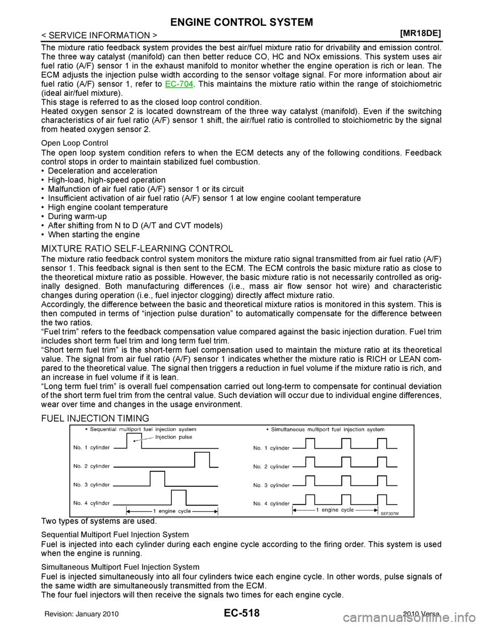
FUEL INJECTION TIMING
Two types of systems are used.
Sequential Multiport Fuel Injection System
Fuel is injected into each cylinder during each engine cycle according to the firing order. This system is used
when the engine is running.
Simultaneous Multiport Fuel Injection System
Fuel is injected simultaneously into all four cylinders twice each engine cycle. In other words, pulse signals of
the same width are simultaneously transmitted from the ECM.
The four fuel injectors will then receive the signals two times for each engine cycle.
SEF337W
Revision: January 20102010 Versa
Page 1784 of 3745
ENGINE CONTROL SYSTEMEC-519
< SERVICE INFORMATION > [MR18DE]
C
D
E
F
G H
I
J
K L
M A
EC
NP
O
This system is used when the engine is being started and/or if the fail-safe system (CPU) is operating.
FUEL SHUT-OFF
Fuel to each cylinder is cut off during deceleration, operation of the engine at excessively high speeds or oper-
ation of the vehicle at excessively high speeds.
Electronic Ignition (EI) SystemINFOID:0000000005532382
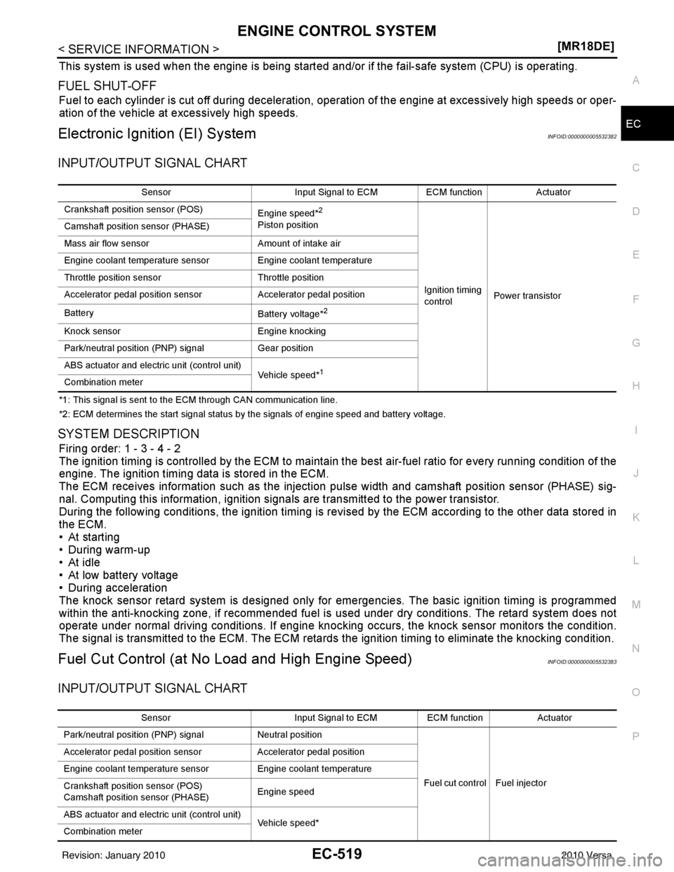
INPUT/OUTPUT SIGNAL CHART
*1: This signal is sent to the ECM through CAN communication line.
*2: ECM determines the start signal status by the signals of engine speed and battery voltage.
SYSTEM DESCRIPTION
Firing order: 1 - 3 - 4 - 2
The ignition timing is controlled by the ECM to maintain the best air-fuel ratio for every running condition of the
engine. The ignition timing data is stored in the ECM.
The ECM receives information such as the injecti
on pulse width and camshaft position sensor (PHASE) sig-
nal. Computing this information, ignition si gnals are transmitted to the power transistor.
During the following conditions, the ignition timing is revi sed by the ECM according to the other data stored in
the ECM.
• At starting
• During warm-up
•At idle
• At low battery voltage
• During acceleration
The knock sensor retard system is designed only for emergencies. The basic ignition timing is programmed
within the anti-knocking zone, if recommended fuel is used under dry conditions. The retard system does not
operate under normal driving conditions. If engine knocking occurs, the knock sensor monitors the condition.
The signal is transmitted to the ECM. The ECM retards the ignition timing to eliminate the knocking condition.
Fuel Cut Control (at No Load and High Engine Speed)INFOID:0000000005532383
INPUT/OUTPUT SIGNAL CHART
Sensor Input Signal to ECMECM functionActuator
Crankshaft position sensor (POS) Engine speed*
2
Piston position
Ignition timing
controlPower transistor
Camshaft position sensor (PHASE)
Mass air flow sensor
Amount of intake air
Engine coolant temperature sensor Engine coolant temperature
Throttle position sensor Throttle position
Accelerator pedal position sensor Accelerator pedal position
Battery Battery voltage*
2
Knock sensor Engine knocking
Park/neutral position (PNP) signal Gear position
ABS actuator and electric unit (control unit) Vehicle speed*
1Combination meter
SensorInput Signal to ECMECM functionActuator
Park/neutral position (PNP) signal Neutral position
Fuel cut control Fuel injector
Accelerator pedal position sensor
Accelerator pedal position
Engine coolant temperature sensor Engine coolant temperature
Crankshaft position sensor (POS)
Camshaft position sensor (PHASE) Engine speed
ABS actuator and electric unit (control unit) Vehicle speed*
Combination meter
Revision: January 20102010 Versa
Page 1786 of 3745
AIR CONDITIONING CUT CONTROLEC-521
< SERVICE INFORMATION > [MR18DE]
C
D
E
F
G H
I
J
K L
M A
EC
NP
O
AIR CONDITIONING
CUT CONTROL
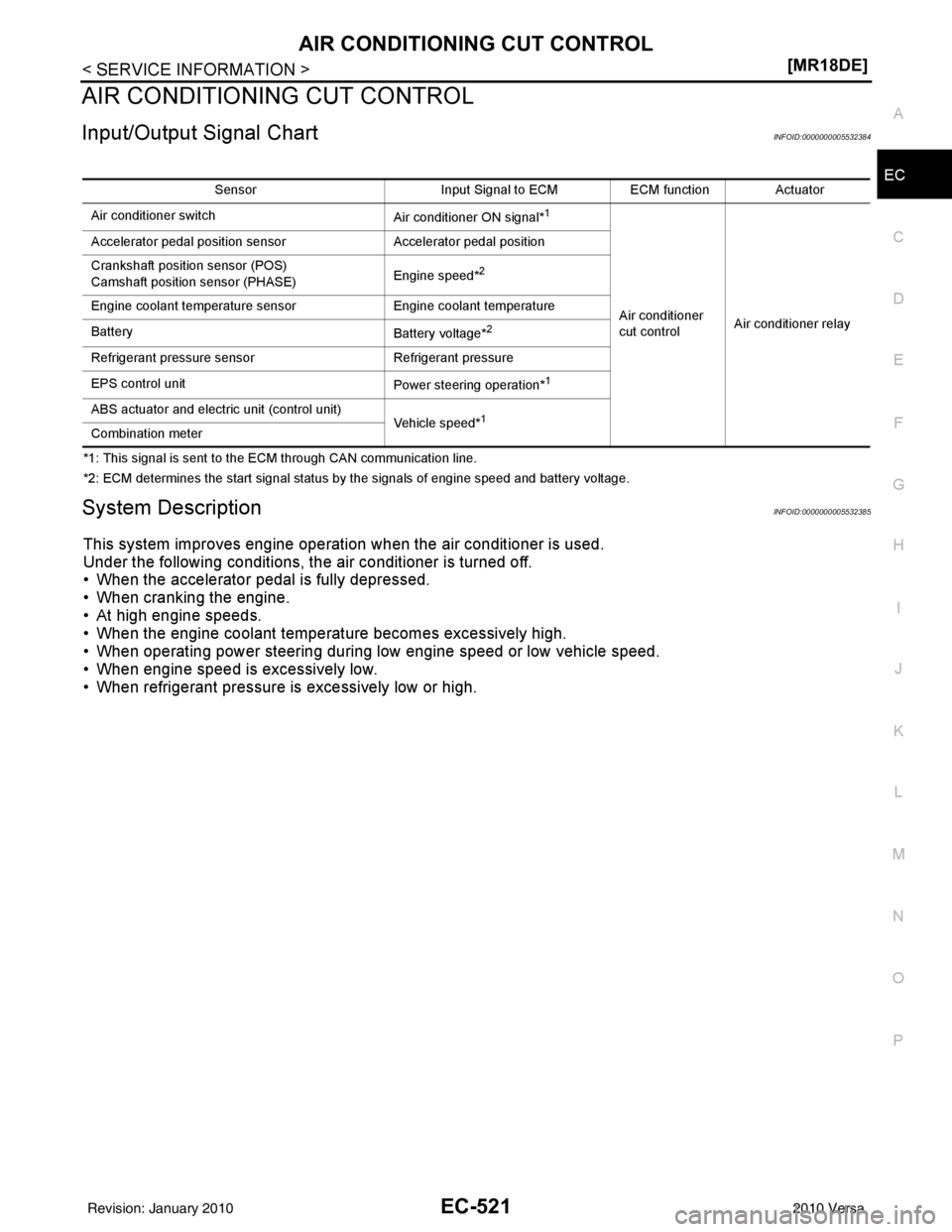
Input/Output Signal ChartINFOID:0000000005532384
*1: This signal is sent to the ECM through CAN communication line.
*2: ECM determines the start signal status by the signals of engine speed and battery voltage.
System DescriptionINFOID:0000000005532385
This system improves engine operation when the air conditioner is used.
Under the following conditions, the air conditioner is turned off.
• When the accelerator pedal is fully depressed.
• When cranking the engine.
• At high engine speeds.
• When the engine coolant temperature becomes excessively high.
• When operating power steering during low engine speed or low vehicle speed.
• When engine speed is excessively low.
• When refrigerant pressure is excessively low or high.
Sensor Input Signal to ECMECM functionActuator
Air conditioner switch Air conditioner ON signal*
1
Air conditioner
cut controlAir conditioner relay
Accelerator pedal position sensor
Accelerator pedal position
Crankshaft position sensor (POS)
Camshaft position sensor (PHASE) Engine speed*
2
Engine coolant temperature sensor
Engine coolant temperature
Battery Battery voltage*
2
Refrigerant pressure sensorRefrigerant pressure
EPS control unit Power steering operation*
1
ABS actuator and electric unit (control unit)
Vehicle speed*1
Combination meter
Revision: January 20102010 Versa
Page 1787 of 3745
EC-522
< SERVICE INFORMATION >[MR18DE]
AUTOMATIC SPEED CONTROL DEVICE (ASCD)
AUTOMATIC SPEED CONTROL DEVICE (ASCD)
System DescriptionINFOID:0000000005532386
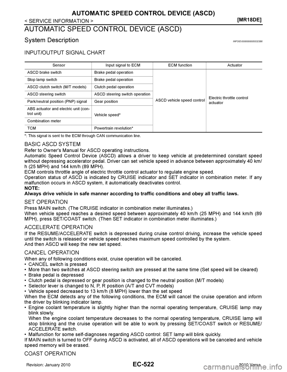
INPUT/OUTPUT SIGNAL CHART
*: This signal is sent to the ECM through CAN communication line.
BASIC ASCD SYSTEM
Refer to Owner's Manual for ASCD operating instructions.
Automatic Speed Control Device (ASCD) allows a driver to keep vehicle at predetermined constant speed
without depressing accelerator pedal. Driver can set
vehicle speed in advance between approximately 40 km/
h (25 MPH) and 144 km/h (89 MPH).
ECM controls throttle angle of electric thro ttle control actuator to regulate engine speed.
Operation status of ASCD is indicated by CRUISE indi cator and SET indicator in combination meter. If any
malfunction occurs in ASCD system, it automatically deactivates control.
NOTE:
Always drive vehicle in safe manner according to traffic conditions and obey all traffic laws.
SET OPERATION
Press MAIN switch. (The CRUISE indicator in combination meter illuminates.)
When vehicle speed reaches a desired speed between approximately 40 km/h (25 MPH) and 144 km/h (89
MPH), press SET/COAST switch. (Then SET indi cator in combination meter illuminates.)
ACCELERATE OPERATION
If the RESUME/ACCELERATE switch is depressed during cruise control driving, increase the vehicle speed
until the switch is released or vehicle speed reaches maximum speed controlled by the system.
And then ASCD will keep the new set speed.
CANCEL OPERATION
When any of following conditions exist, cruise operation will be canceled.
• CANCEL switch is pressed
• More than two switches at ASCD steering switch are pressed at the same time (Set speed will be cleared)
• Brake pedal is depressed
• Clutch pedal is depressed or gear position is changed to the neutral position (M/T models)
• Selector lever is changed to N, P, R position (A/T and CVT models)
• Vehicle speed decreased to 13 km/h (8 MPH) lower than the set speed
When the ECM detects any of the following conditions, the ECM will cancel the cruise operation and inform
the driver by blinking indicator lamp.
• Engine coolant temperature is slightly higher than the normal operating temperature, CRUISE lamp may
blink slowly.
When the engine coolant temperature decreases to the normal operating temperature, CRUISE lamp will
stop blinking and the cruise operation will be able to work by pressing SET/COAST switch or RESUME/
ACCELERATE switch.
• Malfunction for some self-diagnoses regarding ASCD control: SET lamp will blink quickly.
If MAIN switch is turned to OFF during ASCD is activated, all of ASCD operations will be canceled and vehicle
speed memory will be erased.
COAST OPERATION
Sensor Input signal to ECM ECM functionActuator
ASCD brake switch Brake pedal operation
ASCD vehicle speed controlElectric throttle control
actuator
Stop lamp switch
Brake pedal operation
ASCD clutch switch (M/T models) Clutch pedal operation
ASCD steering switch ASCD steering switch operation
Park/neutral position (PNP) signal Gear position
ABS actuator and electric unit (con-
trol unit) Vehicle speed*
Combination meter
TCM Powertrain revolution*
Revision: January 20102010 Versa
Page 1845 of 3745
EC-580
< SERVICE INFORMATION >[MR18DE]
BASIC SERVICE PROCEDURE
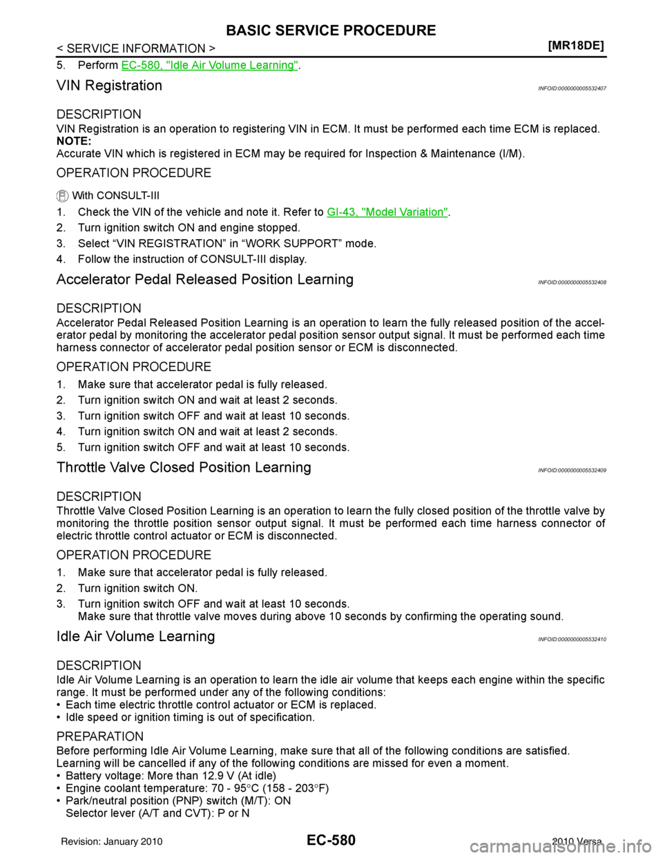
5. Perform
EC-580, "Idle Air Volume Learning".
VIN RegistrationINFOID:0000000005532407
DESCRIPTION
VIN Registration is an operation to registering VIN in ECM. It must be performed each time ECM is replaced.
NOTE:
Accurate VIN which is registered in ECM ma y be required for Inspection & Maintenance (I/M).
OPERATION PROCEDURE
With CONSULT-III
1. Check the VIN of the vehicle and note it. Refer to GI-43, "Model Variation".
2. Turn ignition switch ON and engine stopped.
3. Select “VIN REGISTRATION ” in “WORK SUPPORT” mode.
4. Follow the instruction of CONSULT-III display.
Accelerator Pedal Released Position LearningINFOID:0000000005532408
DESCRIPTION
Accelerator Pedal Released Position Learning is an operation to learn the fully released position of the accel-
erator pedal by monitoring the accelerator pedal positi on sensor output signal. It must be performed each time
harness connector of accelerator pedal pos ition sensor or ECM is disconnected.
OPERATION PROCEDURE
1. Make sure that accelerator pedal is fully released.
2. Turn ignition switch ON and wait at least 2 seconds.
3. Turn ignition switch OFF and wait at least 10 seconds.
4. Turn ignition switch ON and wait at least 2 seconds.
5. Turn ignition switch OFF and wait at least 10 seconds.
Throttle Valve Closed Position LearningINFOID:0000000005532409
DESCRIPTION
Throttle Valve Closed Position Learning is an operation to l earn the fully closed position of the throttle valve by
monitoring the throttle position sensor output signal . It must be performed each time harness connector of
electric throttle control actuator or ECM is disconnected.
OPERATION PROCEDURE
1. Make sure that accelerator pedal is fully released.
2. Turn ignition switch ON.
3. Turn ignition switch OFF and wait at least 10 seconds. Make sure that throttle valve moves during above 10 seconds by confirming the operating sound.
Idle Air Volume LearningINFOID:0000000005532410
DESCRIPTION
Idle Air Volume Learning is an operation to learn the idle air volume that keeps each engine within the specific
range. It must be performed under any of the following conditions:
• Each time electric throttle control actuator or ECM is replaced.
• Idle speed or ignition timing is out of specification.
PREPARATION
Before performing Idle Air Volume Learning, make sure that all of the following conditions are satisfied.
Learning will be cancelled if any of the follo wing conditions are missed for even a moment.
• Battery voltage: More than 12.9 V (At idle)
• Engine coolant temperature: 70 - 95 °C (158 - 203° F)
• Park/neutral position (PNP) switch (M/T): ON
Selector lever (A/T and CVT): P or N
Revision: January 20102010 Versa
Page 1855 of 3745
EC-590
< SERVICE INFORMATION >[MR18DE]
TROUBLE DIAGNOSIS
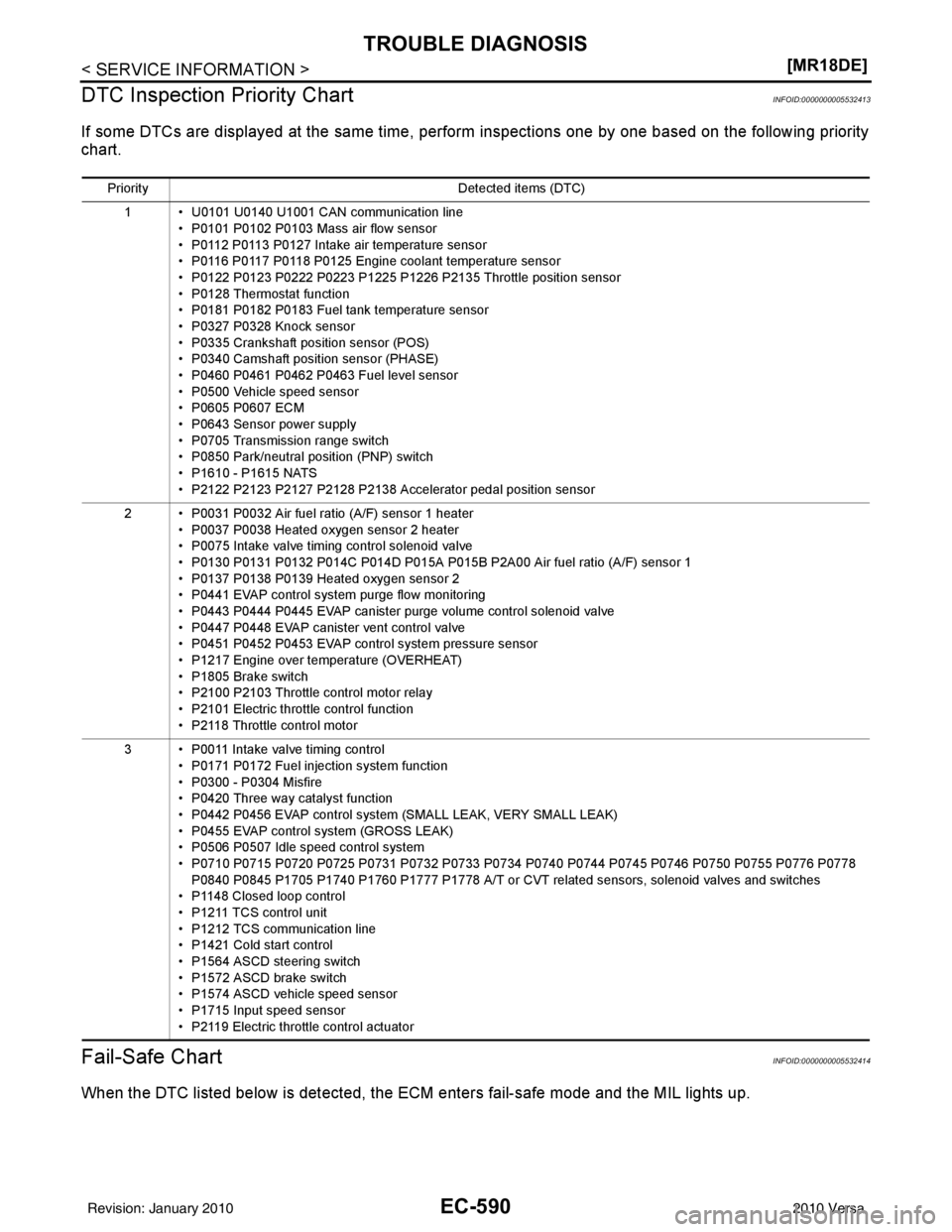
DTC Inspection Priority Chart
INFOID:0000000005532413
If some DTCs are displayed at the same time, perform inspections one by one based on the following priority
chart.
Fail-Safe ChartINFOID:0000000005532414
When the DTC listed below is detected, the ECM enters fail-safe mode and the MIL lights up.
Priority Detected items (DTC)
1 • U0101 U0140 U1001 CAN communication line • P0101 P0102 P0103 Mass air flow sensor
• P0112 P0113 P0127 Intake air temperature sensor
• P0116 P0117 P0118 P0125 Engine coolant temperature sensor
• P0122 P0123 P0222 P0223 P1225 P1226 P2135 Throttle position sensor
• P0128 Thermostat function
• P0181 P0182 P0183 Fuel tank temperature sensor
• P0327 P0328 Knock sensor
• P0335 Crankshaft position sensor (POS)
• P0340 Camshaft position sensor (PHASE)
• P0460 P0461 P0462 P0463 Fuel level sensor
• P0500 Vehicle speed sensor
• P0605 P0607 ECM
• P0643 Sensor power supply
• P0705 Transmission range switch
• P0850 Park/neutral position (PNP) switch
• P1610 - P1615 NATS
• P2122 P2123 P2127 P2128 P2138 Accelerator pedal position sensor
2 • P0031 P0032 Air fuel ratio (A/F) sensor 1 heater • P0037 P0038 Heated oxygen sensor 2 heater
• P0075 Intake valve timing control solenoid valve
• P0130 P0131 P0132 P014C P0 14D P015A P015B P2A00 Air fuel ratio (A/F) sensor 1
• P0137 P0138 P0139 Heated oxygen sensor 2
• P0441 EVAP control system purge flow monitoring
• P0443 P0444 P0445 EVAP canister purge volume control solenoid valve
• P0447 P0448 EVAP canister vent control valve
• P0451 P0452 P0453 EVAP control system pressure sensor
• P1217 Engine over temperature (OVERHEAT)
• P1805 Brake switch
• P2100 P2103 Throttle control motor relay
• P2101 Electric throttle control function
• P2118 Throttle control motor
3 • P0011 Intake valve timing control • P0171 P0172 Fuel injection system function
• P0300 - P0304 Misfire
• P0420 Three way catalyst function
• P0442 P0456 EVAP co ntrol system (SMALL LEAK, VERY SMALL LEAK)
• P0455 EVAP control system (GROSS LEAK)
• P0506 P0507 Idle speed control system
• P0710 P0715 P0720 P0725 P0731 P0732 P0733 P0734 P0740 P0744 P0745 P0746 P0750 P0755 P0776 P0778 P0840 P0845 P1705 P1740 P1760 P1777 P1778 A/T or CVT related sensors, solenoid valves and switches
• P1148 Closed loop control
• P1211 TCS control unit
• P1212 TCS communication line
• P1421 Cold start control
• P1564 ASCD steering switch
• P1572 ASCD brake switch
• P1574 ASCD vehicle speed sensor
• P1715 Input speed sensor
• P2119 Electric throttle control actuator
Revision: January 20102010 Versa